Nibe AG-CH10 Series User guide

N.O
LEK
AG-CH10
SE
Installatörshandbok
Kondensvattenrör AG-CH10
GB
Installer manual
Condensation water pipe AG-CH10
DE
Installateurhandbuch
Kondenswasserschlauch AG-CH10
FI
Asentajan käsikirja
Vedenpoistoputki AG-CH10
IHB 1626-2
331671


Svenska
Allmänt
Tillbehöret AG-CH10 används för att på ett säkert sätt
leda bort det mesta av kondensvattnet från luft/luft-
värmepumpen till frostfri uppsamlingspunkt.
Tillbehöret gäller för NIBEs följande produkter:
■AG-AA10
■AG-AC10
OBS!
Det är viktigt för värmepumpens funktion att
avledningen av kondensvattnet fungerar samt
att utloppet på kondensvattenröret är placerat
så att huset inte kan ta skada.
Värmekabeln startar automatiskt vid en utetemperatur
av 0 °C. När temperaturen når över 2 °C stängs värmeka-
beln av igen.
OBS!
Installationen av AG-CH10 är kritisk för maski-
nens funktion. Läs hela manualen!
TIPS!
Se även installatörshandboken för AG-
AA10/AG-AC10.
Innehåll
Isolerad slang (innerdiameter 40 mm)1 st
Ellåda1 st
Avloppspip1 st
Värmekabel1 st
Slangklämma1 st
Säkring1 st
Buntband2 st
AG-CH10 finns i tre längder
AG-CH10 finns i tre längder. Här ser du ett exempel på installationslängden.
Installationslängd
Installationslängd
InstallationslängdSlanglängdProduktBenämningRSK nrArt nr
1 m utan vattenlås1 mAG-AA10 och
AG-AC10
AG-CH10-10624 77 38067 466
1–2,2 m med vattenlås3 mAG-CH10-30624 77 39067 467
2,2-5,2 m med vattenlås6 mAG-CH10-60624 77 40067 468
AG-CH10 | SE4

Röranslutning
Allmänt
■Rörinstallationen ska utföras enligt gällande regler.
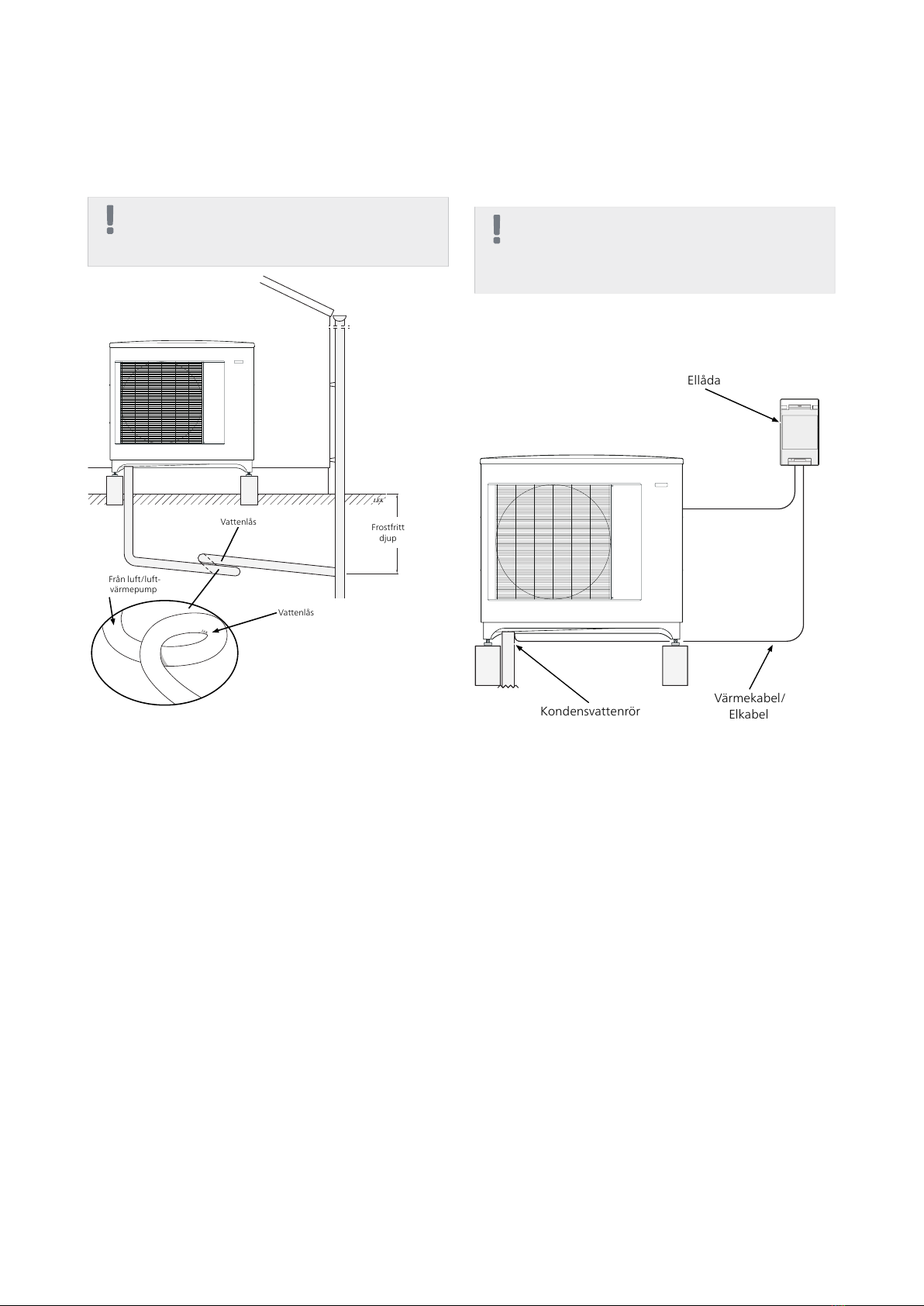
■Vi rekommenderar tre sätt att leda bort kondensvatt-
net, till avlopp inomhus (med reservation för lokala
bestämmelser och regler), stenkista, stuprörsavlopp
eller annan frostfri uppsamlingspunkt.
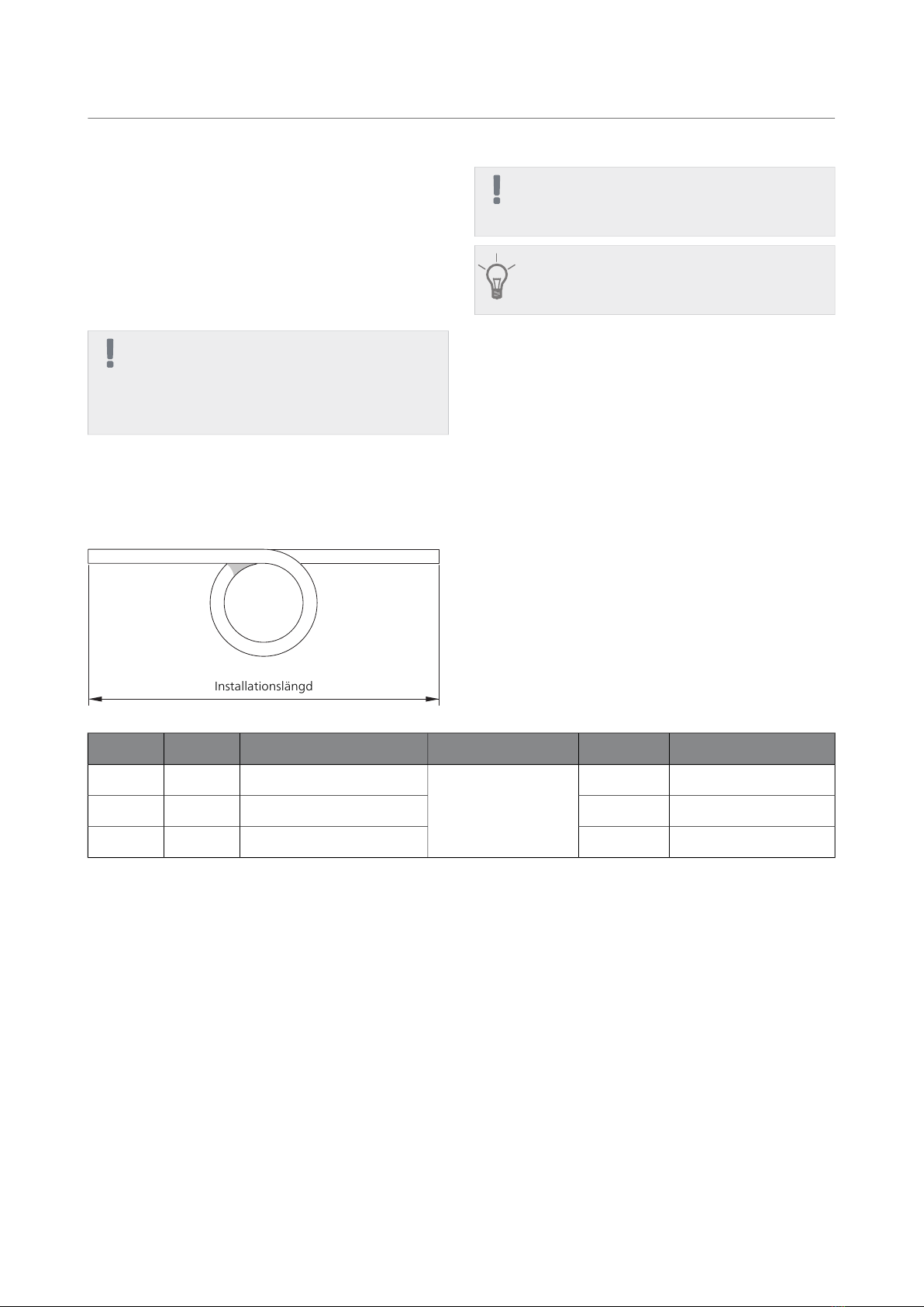
■Vid gjutning av fundament ska hål för AG-CH10 ha en
invändig diameter om 110 mm.
■Dra röret med en fallande lutning från luft/vatten-
värmepumpen.
■Isoleringen av AG-CH10 ska sluta tätt mot undersidan
av kondensvattentråget.
■Utloppet från AG-CH10 måste placeras på frostfritt
djup alternativt inomhus (med reservation för lokala
bestämmelser och regler).
■Utloppet från AG-CH10 måste klara av att ta emot upp
till 100 liter kondensvatten per dygn.
■Installationen ska förses med vattenlås där luftcirkula-
tion kan förekomma i kondensvattenröret.
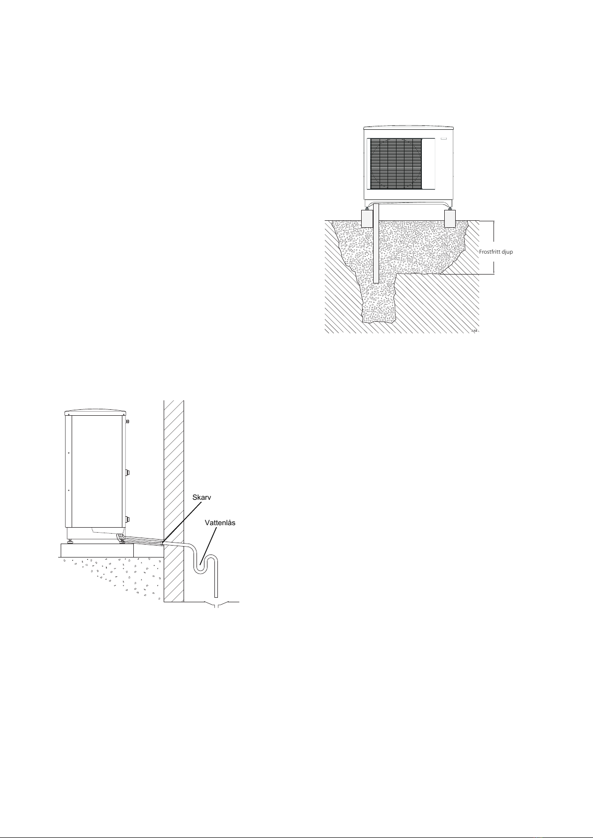
Avlopp inomhus
Vattenlås
Skarv
Kondensvattnet leds till avlopp inomhus (med reserva-
tion för lokala bestämmelser och regler).
Dra röret med en fallande lutning från luft/vatten-vär-
mepumpen.
Kondensvattenröret måste ha ett vattenlås för att för-
hindra luftcirkulation i röret.
AG-CH10 skarvas enligt bild. Rördragning insida hus in-
går ej.
Stenkista
LEK
Frostfritt djup
Frostfritt djup
Om huset har källare ska stenkistan placeras på ett så-
dant sätt att kondensvattnet inte påverkar huset. Annars
kan stenkistan placeras rakt under värmepumpen.
Utloppet på kondensvattenröret måste ligga på frostfritt
djup.
5AG-CH10 | SE

Stuprörsavlopp
OBS!
Böj slangen så att ett vattenlås bildas, se illustra-
tion.
LEK
Frostfritt
djup
Vattenlås
Frostfritt
djup
Vattenlås
LEK
Från luft/luft-
värmepump
■Utloppet på kondensvattenröret måste ligga på frost-
fritt djup.
■Dra röret med en fallande lutning från luft/luft-värme-
pumpen.
■Kondensvattenröret måste ha ett vattenlås för att
förhindra luftcirkulation i röret.
■Installationslängden kan justeras genom storleken på
vattenlåset.
Elinkoppling
OBS!
Elektrisk installation och ledningsdragning ska
utföras under överinseende av behörig elinstal-
latör.
Allmänt
Inkoppling mellan AG-CH10 och AG-AA10 / AG-AC10
sker via den medföljande ellådan enligt bild.
Ellåda
Kondensvattenrör Värmekabel/
Elkabel
AG-CH10 är försedd med plint för anslutning av värme-
kabel samt utomhusenhet. Anslutningen är avsäkrad
med 250 mA från fabrik.
Om annan kabellängd än 3 m används måste säkringen
(F3) bytas ut mot medlevererad.
AG-CH10 | SE6

Säkringens placering AG-CH10
F3
Säkring
Art.nrSäkring (F3)Ptot (W)Längd
(m)
718 085T100mA/250V151
518 900*T250mA/250V453
718 086T500mA/250V906
*Monterad från fabrik.
Anslutning av värmekabel
Anslutning av värmekabel görs till kopplingsplint PE, N
och L i den medföljande ellådan enligt följande bild:
N
L
1
NN
2/1 1/2
Ell daVärmekabel
Värmekabel Ellåda
F3
Anslutning av AG-CH10 till utomhusenhet
AG-AA10
Ta bort skyddslocket enligt anvisningarna i utomhusen-
hetens installatörshandbok och anslut AG-CH10 via ut-
omhusenhetens toppklämmor.
Toppklämmor
Toppklämmorna i AG-AA10 ansluts till 1/2 och N i jord-
felsbrytaren samt PE i kopplingsplint enligt följande bild:
N
L
1
NN
2/1 1/2
UtomhusenhetEll da
Ellåda Utomhusenhet
F3
Kabeldragning
Följande avsnitt beskriver rekommenderad kabeldrag-
ning mellan ellådan och kondensvattenröret. Dra värme-
kabel (EB14) genonom genomföringen på undersidan.
Övergång mellan elkabel och värmekabel ska ske enligt
bild.
1. Lokalisera anslutningen för AG-CH10 på utomhusen-
heten.
7AG-CH10 | SE

2. Fixera avloppspipen, se bild.
1. 2. 3.
LEK
1. 2. 3.
LEK
1. 2. 3.
LEK
3. Dra värmekabeln genom kondensvattenröret.
4. Dra ned isoleringen något, anslut slangen till avlopps-
pipen och dra åt slangklämman, se bild.
LEK
1.
2.
3.
5. Sträck värmekabeln så att markeringen hamnar så
nära avloppspipen som möjligt, se bild.
LEK
Avloppspip
Markering
6. Anslut kabeln till den medföljande ellådan enligt
avsnittet "Anslutning av värmekabel" på sida 7.
(Kontrollera säkring enligt tabell, se sidan 7.)
OBS!
Värmekabeln får ej klippas!
Anslutning av AG-CH10 till utomhusenhet
AG-AC10
Ta bort skyddslocket enligt anvisningarna i utomhusen-
hetens installatörshandbok och anslut AG-CH10 via ut-
omhusenhetens toppklämmor.
GRÅ
VIT
GRÖN/GUL
AG-CH10
Toppklämmorna i AG-AC10 ansluts till 1/2 och N i jord-
felsbrytaren samt PE i kopplingsplint enligt följande bild:
N
L
1
NN
2/1 1/2
UtomhusenhetEll da
Ellåda Utomhusenhet
F3
Kabeldragning
Följande avsnitt beskriver rekommenderad kabeldrag-
ning mellan ellådan och kondensvattenröret. Dra värme-
kabel (EB14) genonom genomföringen på undersidan.
Övergång mellan elkabel och värmekabel ska ske enligt
bild.
1. Lokalisera anslutningen för AG-CH10 på utomhusen-
heten.
AG-CH10 | SE8

2. Fixera avloppspipen, se bild.
1. 2. 3.
LEK
1. 2. 3.
LEK
1. 2. 3.
LEK
3. Dra värmekabeln genom kondensvattenröret.
4. Dra ned isoleringen något, anslut slangen till avlopps-
pipen och dra åt slangklämman, se bild.
LEK
1.
2.
3.
5. Sträck värmekabeln så att markeringen hamnar så
nära avloppspipen som möjligt, se bild.
LEK
Avloppspip
Markering
6. Anslut kabeln till den medföljande ellådan enligt
avsnittet "Anslutning av värmekabel" på sida 7.
(Kontrollera säkring enligt tabell, se sidan 7.)
OBS!
Värmekabeln får ej klippas!
9AG-CH10 | SE

English
General
The accessory AG-CH10 is used to safely lead away most
of the condensation from the air/air heat pump to a
frost-free collection point.
The accessory applies to NIBE's following products:
■AG-AA10
■AG-AC10
NOTE
It is important to the heat pump function that
condensation water is led away and that the
drain for the condensation water run off is not
positioned so that it can cause damage to the
house.
The heating cable starts automatically at an outdoor
temperature of 0 °C. When the temperature exceeds
2 °C the heating cable switches off again.
NOTE
The installation of AG-CH10 is critical to the
machine's function. Read the entire manual!
TIP
Also see the Installer manual for AG-AA10/AG-
AC10.
Contents
Insulated hose (inner diameter 40 mm)1 x
Electrical cabinet1 x
Drain spout1 x
Heating cable1 x
Hose clamp1 x
Fuse1 x
Cable ties2 x
AG-CH10 available in three lengths
AG-CH10 is available in three lengths. Here you can see an example of the installation length.
Installationslängd
Installation length
Installation lengthHose lengthProductNamePart No.
1 m without water seal1 mAG-AA10 and
AG-AC10
AG-CH10-10067 466
1–2,2 m with water seal3 mAG-CH10-30067 467
2,2–5,2 m with water seal6 mAG-CH10-60067 468
AG-CH10 | GB10

Pipe connections
General
■Pipe installation must be carried out in accordance
with current norms and directives.
■We recommend three ways of leading off condensa-
tion water; to an indoor drain (subject to local rules
and regulations), stone caisson, gutter drainage or
other frost free collection point.
■When casting the base, the holes for AG-CH10 must
have an internal diameter of 110 mm.
■Route the pipe downward from the air/water heat
pump.
■The insulation of AG-CH10 must seal against the bot-
tom of the condensation water trough.
■The drain from AG-CH10 must be positioned at frost
free depth or indoors (subject to local rules and regu-
lations).
■The drain from AG-CH10 must be able to receive up
to 100litres of condensation per day.
■The installation must be equipped with a water seal
where air circulation can occur in the condensation
water pipe.
Drain indoors
Water seal
Joint
The condensation water is lead to an indoor drain (sub-
ject to local rules and regulations).
Route the pipe downward from the air/water heat pump.
The condensation water pipe must have a water seal to
prevent air circulation in the pipe.
AG-CH10 spliced as illustrated. Pipe routing inside house
not included.
Stone caisson
LEK
Frostfritt djup
Frost proof
depth
If the house has a cellar the stone caisson must be posi-
tioned so that condensation water does not affect the
house. Otherwise the stone caisson can be positioned
directly under the heat pump.
The outlet of the condensation water pipe must be at
frost free depth.
11AG-CH10 | GB

Gutter drainage
NOTE
Bend the hose to create a water seal, see illustra-
tion.
LEK
Frostfritt
djup
Water seal
Frost free
depth
Water seal
LEK
Exhaust air/air heat
pump
■The outlet of the condensation water pipe must be at
frost free depth.
■Route the pipe downward from the air/air heat pump.
■The condensation water pipe must have a water seal
to prevent air circulation in the pipe.
■The installation length can be adjusted by the size of
the water seal.
Electrical connection
NOTE
The electrical installation and wiring must be
carried out under the supervision of an author-
ised electrician.
General
Connection between AG-CH10 and AG-AA10 / AG-AC10
is made via the enclosed electrical distribution box as il-
lustrated.
Electrical cabinet
Condensation water pipe Heating cable/
Electrical cable
AG-CH10 is equipped with terminal board for connection
of heating cable and outdoor unit. The connection is
fitted with a 250 mA fuse at the factory.
If a cable length other than 3 m is used, the fuse (F3)
must be replaced with the one enclosed.
AG-CH10 | GB12

Fuse location AG-CH10
F3
Fuse
Part No.Fuse (F3)Ptot (W)Length
(m)
718 085T100mA/250V151
518 900*T250mA/250V453
718 086T500mA/250V906
*Fitted at the factory.
Connection of heating cable
Connect the heating cable to terminal block PE, N and
L in the enclosed electrical distribution box as illustrated
below:
N
L
1
NN
2/1 1/2
Ell daVärmekabel
Heating cable Electrical cabinet
F3
Connection of AG-CH10 to the outdoor unit
AG-AA10
Remove the protective cover according to the instruc-
tions in the outdoor unit's installer manual and connect
AG-CH10 via the outdoor unit's top clamps.
Top clamps
The top clamps in AG-AA10 are connected to 1/2 and
N in the earth circuit breaker as well as PE in terminal
block as illustrated below:
N
L
1
NN
2/1 1/2
UtomhusenhetEll da
Electrical cabinet Outdoor unit
F3
Cable routing
The following section describes the recommended cable
routing between the electrical distribution box and the
condensation pipe. Route the heating cable (EB14)
through the lead-in on the underneath. Transition
between electrical cable and heating cable must occur
as illustrated.
1. Locate the connection for AG-CH10 on the outdoor
unit.
13AG-CH10 | GB

2. Secure the drain pipe, as illustrated.
1. 2. 3.
LEK
1. 2. 3.
LEK
1. 2. 3.
LEK
3. Route the heating cable through the condensation
water pipe.
4. Pull the insulation down slightly, connect the hose
to the drain pipe and tighten the hose clamp, as il-
lustrated.
LEK
1.
2.
3.
5. Lay the heating cable so that the marking is as close
to the drain pipe as possible, as illustrated.
LEK
Drain spout
Marking
6. Connect the cable to the enclosed electrical distribu-
tion box according to section "Connection of the
heating cable" on page 13. (Check the fuse according
to the table, see page 13.)
NOTE
Do not cut the heating cable!
Connection of AG-CH10 to the outdoor unit
AG-AC10
Remove the protective cover according to the instruc-
tions in the outdoor unit's installer manual and connect
AG-CH10 via the outdoor unit's top clamps.
GREY
WHITE
GREEN/YELLOW
AG-CH10
The top clamps in AG-AC10 are connected to 1/2 and N
in the earth circuit breaker as well as PE in terminal block
as illustrated below:
N
L
1
NN
2/1 1/2
UtomhusenhetEll da
Electrical cabinet Outdoor unit
F3
Cable routing
The following section describes the recommended cable
routing between the electrical distribution box and the
condensation pipe. Route the heating cable (EB14)
through the lead-in on the underneath. Transition
between electrical cable and heating cable must occur
as illustrated.
AG-CH10 | GB14

1. Locate the connection for AG-CH10 on the outdoor
unit.
2. Secure the drain pipe, as illustrated.
1. 2. 3.
LEK
1. 2. 3.
LEK
1. 2. 3.
LEK
3. Route the heating cable through the condensation
water pipe.
4. Pull the insulation down slightly, connect the hose
to the drain pipe and tighten the hose clamp, as il-
lustrated.
LEK
1.
2.
3.
5. Lay the heating cable so that the marking is as close
to the drain pipe as possible, as illustrated.
LEK
Drain spout
Marking
6. Connect the cable to the enclosed electrical distribu-
tion box according to section "Connection of the
heating cable" on page 13. (Check the fuse according
to the table, see page 13.)
NOTE
Do not cut the heating cable!
15AG-CH10 | GB

Deutsch
Allgemeines
Das Zubehör AG-CH10 leitet auf sichere Weise das
meiste Kondenswasser von der Luft-/Luftwärmepumpe
zu einem frostfreien Sammelpunkt ab.
Das Zubehör gilt für folgende NIBE-Produkte:
■AG-AA10
■AG-AC10
HINWEIS!
Für die Wärmepumpenfunktion ist es wichtig,
dass die Kondenswasserableitung korrekt er-
folgt und dass der Auslass des Kondenswasser-
schlauchs so positioniert ist, dass das Gebäude
nicht beschädigt werden kann.
Das Heizkabel wird bei einer Außenlufttemperatur von
0 °C automatisch aktiviert. Bei einer Temperatur über
2 °C wird das Heizkabel wieder deaktiviert.
HINWEIS!
Die Installation von AG-CH10 ist zentraler Bedeu-
tung für die Gerätefunktion. Lesen Sie das ge-
samte Handbuch!
TIP!
Siehe auch Installateurhandbuch für AG-
AA10/AG-AC10.
Inhalt
Isolierter Schlauch (Innendurchmesser 40 mm)1 St.
Schaltschrank1 St.
Abflusstülle1 St.
Heizkabel1 St.
Schlauchklemme1 St.
Sicherung1 St.
Kabelbinder2 St.
AG-CH10 ist in drei Längen verfügbar
AG-CH10 ist in drei Längen verfügbar. Hier sehen Sie ein Beispiel für die Installationslänge.
Installationslängd
Installationslänge
InstallationslängeSchlauchlän-
ge
ProduktBezeichnungArt.nr.
1 m ohne Wasserverschluss1 mAG-AA10 und
AG-AC10
AG-CH10-10067 466
1-2,2 m mit Wasserverschluss3 mAG-CH10-30067 467
2,2-5,2 m mit Wasserverschluss6 mAG-CH10-60067 468
AG-CH10 | DE16

Rohranschluss/Durchflussmesser
Allgemeines
■Die Installation muss gemäß den geltenden Vorschrif-
ten vorgenommen werden.
■Wir empfehlen drei Methoden zur Kondenswassera-
bleitung: zu einem Abfluss im Innenbereich (je nach
lokalen Bestimmungen und Vorschriften), in eine
Kiesverfüllung, einen Fallrohrauslass oder einen ande-
ren frostfreien Sammelpunkt.
■Beim Gießen des Fundaments müssen die Löcher für
AG-CH10 einen Innendurchmesser von 110 mm auf-
weisen.
■Verlegen Sie die Leitung mit einem Gefälle von der
Luft/Wasser-Wärmepumpe.
■Die Isolierung von AG-CH10 muss an der Unterseite
der Kondensatauffangwanne dicht abschließen.
■Der Auslass von AG-CH10 muss in frostfreier Tiefe bzw.
im Innenbereich liegen. (Es gelten die lokalen Bestim-
mungen und Vorschriften.)
■Der Auslass von AG-CH10 muss bis zu 100 l Kondens-
wasser pro Tag aufnehmen können.
■Verwenden Sie bei der Installation einen Siphon, wenn
im Kondenswasserschlauch eine Luftzirkulation auftre-
ten kann.
Auslass im Innenbereich
Siphon
Verbindung
Das Kondenswasser wird (je nach lokalen Bestimmungen
und Vorschriften) zum Abfluss im Innenbereich geleitet.
Verlegen Sie die Leitung mit einem Gefälle von der
Luft/Wasser-Wärmepumpe.
Der Kondenswasserschlauch muss über einen Siphon
verfügen, der eine Luftzirkulation und damit eine Ge-
ruchsbildung im Schlauch unterbindet.
AG-CH10 wird gemäß Abbildung verbunden. Eine Lei-
tungsverlegung im Gebäude ist nicht enthalten.
Kiesverfüllung
LEK
Frostfritt djup
Frostfreie
Tiefe
Wenn das Haus über einen Keller verfügt, ist die Kiesver-
füllung so zu platzieren, dass das Kondenswasser keine
Gebäudeschäden verursacht. Andernfalls kann die Kies-
verfüllung direkt unter der Wärmepumpe aufgestellt
werden.
Der Auslass des Kondenswasserschlauchs muss in frost-
freier Tiefe liegen.
17AG-CH10 | DE

Fallrohrauslass
HINWEIS!
Verlegen Sie den Schlauch so, dass ein Siphon
entsteht (siehe Abbildung).
LEK
Frostfritt
djup
Siphon
Frostfreie
Tiefe
Siphon
LEK
Von Luft-
/Luftwärmepumpe
■Der Auslass des Kondenswasserschlauchs muss in
frostfreier Tiefe liegen.
■Verlegen Sie das Rohr mit einem Gefälle von der Luft-
/Luftwärmepumpe.
■Der Kondenswasserschlauch muss über einen Siphon
verfügen, der eine Luftzirkulation und damit eine Ge-
ruchsbildung im Schlauch unterbindet.
■Die Installationslänge lässt sich mithilfe der Siphongrö-
ße anpassen.
Elektrischer Anschluss
HINWEIS!
Elektrische Installation und Leitungsverlegung
müssen unter Aufsicht eines ausgebildeten
Elektroinstallateurs erfolgen.
Allgemeines
Der Anschluss zwischen AG-CH10 und AG-AA10 / AG-
AC10 erfolgt gemäß Abbildung über den beiliegenden
Schaltschrank.
Schaltschrank
Kondenswasserrohr Heizkabel/
Stromkabel
AG-CH10 verfügt über eine Anschlussklemme für Heiz-
kabel und Außeneinheit. Der Anschluss ist werkseitig
mit 250 mA abgesichert.
Soll eine andere Kabellänge als 3 m verwendet werden,
muss die Sicherung (F3) durch die beiliegende Einheit
ersetzt werden.
AG-CH10 | DE18

Sicherungsposition AG-CH10
F3
Sicherung
Art.nr.Sicherung (F3)Pges (W)Länge
(m)
718 085T100mA/250V151
518 900*T250mA/250V453
718 086T500mA/250V906
*Werkseitig montiert.
Anschluss des Heizkabels
Das Heizkabel wird gemäß der folgenden Abbildung mit
Anschlussklemme PE, N und L im beiliegenden Schalt-
schrank verbunden:
N
L
1
NN
2/1 1/2
Ell daVärmekabel
Heizkabel Schaltschrank
F3
Anschluss von AG-CH10 mit Außeneinheit
AG-AA10
Entfernen Sie die Schutzabdeckung gemäß den Vorga-
ben im Installateurhandbuch für die Außeneinheit und
verbinden Sie AG-CH10 über die Aufsatzklemmen an
der Außeneinheit.
Aufsatzklemmen
Die Aufsatzklemmen in AG-AA10 werden gemäß der
folgenden Abbildung mit 1/2 und N im FI-Schutzschalter
sowie mit PE in der Anschlussklemme verbunden:
N
L
1
NN
2/1 1/2
UtomhusenhetEll da
Schaltschrank Außeneinheit
F3
Kabelverlegung
Der folgende Abschnitt beschreibt die empfohlene Ka-
belverlegung zwischen Schaltschrank und Kondenswas-
serrohr. Verlegen Sie das Heizkabel (EB14) durch die
Durchführung an der Unterseite. Der Übergang zwischen
Strom- und Heizkabel muss gemäß Abbildung erfolgen.
1. Ermitteln Sie die Position des Anschlusses für AG-
CH10 an der Außeneinheit.
19AG-CH10 | DE

2. Befestigen Sie die Abflusstülle, siehe Abbildung.
1. 2. 3.
LEK
1. 2. 3.
LEK
1. 2. 3.
LEK
3. Führen Sie das Heizkabel durch den Kondenswasser-
schlauch.
4. Ziehen Sie die Isolierung leicht herab, verbinden Sie
den Schlauch mit der Abflusstülle und ziehen Sie die
Schlauchklemme fest, siehe Abbildung.
LEK
1.
2.
3.
5. Strecken Sie das Heizkabel so, dass sich die Kenn-
zeichnung so nahe wie möglich an der Abflusstülle
befindet, siehe Abbildung.
LEK
Abflusstülle
Kennzeichnung
6. Verbinden Sie das Kabel mit dem beiliegenden
Schaltschrank gemäß dem Abschnitt zum Heizkabel-
anschluss auf Seite 19. (Kontrollieren Sie die Siche-
rung gemäß der Tabelle auf Seite 19.)
HINWEIS!
Das Heizkabel darf nicht gekürzt werden!
Anschluss von AG-CH10 mit Außeneinheit
AG-AC10
Entfernen Sie die Schutzabdeckung gemäß den Vorga-
ben im Installateurhandbuch für die Außeneinheit und
verbinden Sie AG-CH10 über die Aufsatzklemmen an
der Außeneinheit.
GRAU
WEISS
GRÜN/GELB
AG-CH10
Die Aufsatzklemmen in AG-AC10 werden gemäß der
folgenden Abbildung mit 1/2 und N im FI-Schutzschalter
sowie mit PE in der Anschlussklemme verbunden:
N
L
1
NN
2/1 1/2
UtomhusenhetEll da
Schaltschrank Außeneinheit
F3
Kabelverlegung
Der folgende Abschnitt beschreibt die empfohlene Ka-
belverlegung zwischen Schaltschrank und Kondenswas-
serrohr. Verlegen Sie das Heizkabel (EB14) durch die
Durchführung an der Unterseite. Der Übergang zwischen
Strom- und Heizkabel muss gemäß Abbildung erfolgen.
AG-CH10 | DE20
Other manuals for AG-CH10 Series
1
This manual suits for next models
4
Table of contents
Languages:
Other Nibe Heat Pump Accessories manuals