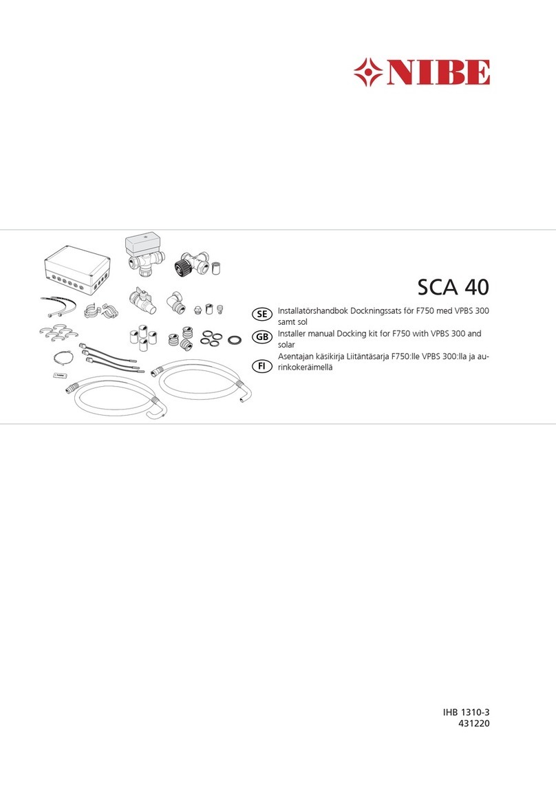
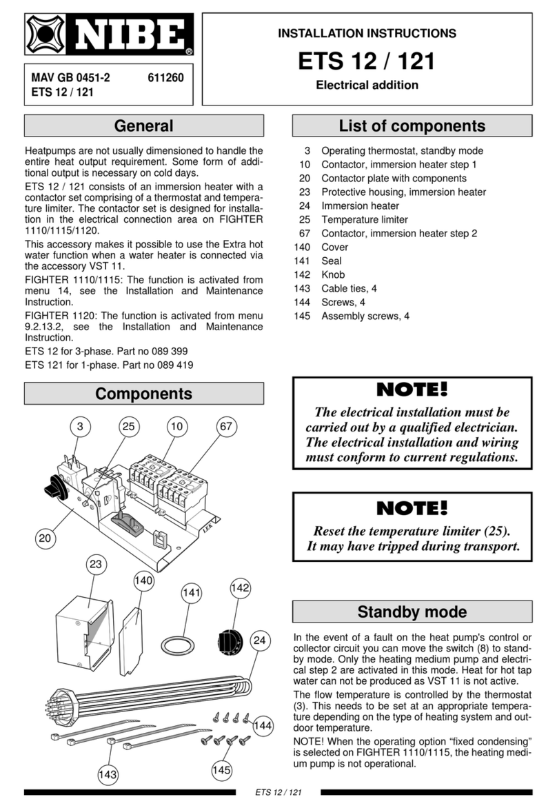
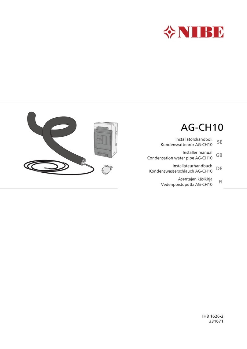
Nibe KVR 10 User guide

Installer manual
LEK
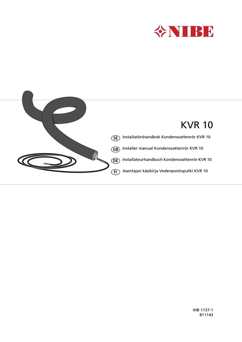
Condensation water
pipe KVR 10
Accessories
IHB GB 1646-3
331785


Table of Contents
41 General
4
Contents
(F2016/F2026/F2030/F2120/F2300)
4Contents (F2040/HBS 05 + AMS 10)
5KVR 10 available in three lengths
62 Pipe connections
6General
6Drain indoors
7Stone caisson
7Gutter drainage
83 Electrical connection
8F2016/F2026
10F2030/F2300
12F2040
19F2120
22HBS 05 + AMS 10
26Item register
3Table of Contents |Condensation water pipe KVR 10

The accessory KVR 10 is used to safely lead away most
of the condensation water from the air/water heat pump
to a frost free collection point.
The accessory is suitable to following products from NIBE:
■■ F2120F2016
■ ■
F2026 F2300
■■ HBS 05 + AMS 10F2030
■F2040
NOTE
It is important to the heat pump function that
condensation water is led away and that the
drain for the condensation water run off is not
positioned so that it can cause damage to the
house.
The heating cable starts automatically at an outdoor
temperature of 1.5 °C. When the temperature exceeds
2 °C the heating cable switches off again.
Contents (F2016/F2026/F2030/F2120/F2300)
Insulated hose (inner diameter 40 mm)1 x
Heating cable1 x
Hose clamp1 x
Fuse1 x
Cable ties6 x
Automatic protection1 x
Contents (F2040/HBS 05 + AMS 10)
Insulated hose (inner diameter 40 mm)1 x
Heating cable1 x
Hose clamp1 x
Fuse1 x
Automatic protection1 x
Plug3 x
Gasket1 x
Connection plate1 x
Cable tie, length 605 mm1 x
Cable tie, length 270 mm2 x
Cable tie, length 200 mm3 x
NOTE
The installation of KVR 10 is critical to the ma-
chine's function. Read the entire manual!
Condensation water pipe KVR 10Chapter 1 | General4
1 General

KVR 10 available in three lengths
Installationslängd
Installation length
KVR 10 is available in three lengths. Here you can see an ex-
ample of the installation length.
Hose length 1 metres
Installation length 1 m without water seal.
Part No.Product
HBS 05 +
AMS 10
F2300F2120F2040F2030F2026F2016KVR 10
067 171XXXXKVR 10-10
067 549XKVR 10-10
067 233XXKVR 10-10
067 234XXKVR 10-10 2x230V
067 553XKVR 10-10 2x230V
Hose length 3 metres
Installation length 1-2.2 m with water seal.
Part No.Product
HBS 05 +
AMS 10
F2300F2120F2040F2030F2026F2016KVR 10
067 172XXXXKVR 10-30
067 550XKVR 10-30
067 235XXKVR 10-30
067 236XXKVR 10-30 2x230V
067 554XKVR 10-30 2x230V
Hose length 6 metres
Installation length 2.2-5.2 m with water seal.
Part No.Product
HBS 05 +
AMS 10
F2300F2120F2040F2030F2026F2016KVR 10
067 173XXXXKVR 10-60
067 551XKVR 10-60
067 237XXKVR 10-60
067 238XXKVR 10-60 2x230V
067 555XKVR 10-60 2x230V
5Chapter 1 | GeneralCondensation water pipe KVR 10

General
Connect KVR 10 to the heat pump's condensation water
trough using the supplied hose clamp.
■Pipe installation must be carried out in accordance
with current norms and directives.
■We recommend three ways of leading off condensa-
tion water; to an indoor drain (subject to local rules
and regulations), stone caisson, gutter drainage or
other frost free collection point.
■When casting the base, the holes for KVR 10 must have
an internal diameter of 110 mm.
■Route the pipe downward from the air/water heat
pump.
■The insulation of KVR 10 must seal against the bottom
of the product's condensation water trough.
■The drain from KVR 10 must be positioned at frost free
depth or indoors (subject to local rules and regula-
tions).
■The drain from KVR 10 must be able to receive up to
100 litres of condensation water per day.
■The installation must be equipped with a water seal
where air circulation can occur in the condensation
water pipe.
Drain indoors
Water seal
Joint
The condensation water is lead to an indoor drain (sub-
ject to local rules and regulations).
Route the pipe downward from the air/water heat pump.
The condensation water pipe must have a water seal to
prevent air circulation in the pipe.
KVR 10 spliced as illustrated. Pipe routing inside house
not included.
Condensation water pipe KVR 10Chapter 2 | Pipe connections6
2 Pipe connections

Stone caisson
LEK
Frostfritt djup
Frost proof
depth
If the house has a cellar the stone caisson must be posi-
tioned so that condensation water does not affect the
house. Otherwise the stone caisson can be positioned
directly under the heat pump.
The outlet of the condensation water pipe must be at
frost free depth.
Gutter drainage
NOTE
Bend the hose to create a water seal, see illustra-
tion.
LEK
Frostfritt
djup
Water seal
Frost free
depth
Water seal
LEK
From air/water heat
pump
■The outlet of the condensation water pipe must be at
frost free depth.
■Route the pipe downward from the air/water heat
pump.
■The condensation water pipe must have a water seal
to prevent air circulation in the pipe.
■The installation length can be adjusted by the size of
the water seal.
7Chapter 2 | Pipe connectionsCondensation water pipe KVR 10

NOTE
All electrical connections must be carried out
by an authorised electrician.
F2016/F2026
F2016/F2026 is equipped with a terminal block (X3) for
a heating cable. The connection is fused with 250 mA
at the factory.
Fuse location
LEK
LEK
F3
X3
Fuse
NIBE Part no.Fuse (F3)Ptot (W)Length
(m)
718 085T100mA/250V151
518 900*T250mA/250V453
718 086T500mA/250V906
*Fitted at the factory.
Electrical connection
Connect external heating cable (EB14) to terminal block
X3:1 and 4 as illustrated below:
5 6 742 31
F2016/F2026
X3
EB14
Heating
cable
F3
KVR10
Condensation water pipe KVR 10Chapter 3 | Electrical connection8
3 Electrical connection

Cable routing
The following image shows recommended cable routing
from distribution box to condensation water trough in
F2016/F2026.. Transition between electrical cable and
heating cable must occur according to image.
1. Remove cover.
2. Thread hose clamp on.
3. Route the heating cable through the condensation
water pipe.
4. Remove the condensation water trough.
5. Route the heating cable through the drain pipe and
lead-in.
6. Pull the insulation down slightly, connect the hose
to the drain pipe and tighten the hose clamp.
7. Push the insulation up towards the trough and install
it using cable ties.
8. Lay the heating cable so that the marking is as close
to the drain pipe as possible.
9. Route the cable to the distribution box as illustrated.
(Extend the cable so that removal of the condensa-
tion water trough is possible, i.e. with some margin.)
10. Use factory fitted cable tie.
11. The distance between the distribution box and the
lead-in to the condensation water trough is approx.
2,000 mm.
12. The length of the non heat conducting section of
the cable needs adjusting. Roll the cable to the cor-
rect length (do not cut).
13. Connect the cable according to the "Electrical con-
nection" image. (Check fuse according to table. See
Fuse page 10.)
14. Reinstall the condensation water trough and cover.
NOTE
Ensure that the marking on the cable is edge to
edge with the drain (see image).
NOTE
Do not cut the heating cable!
LEK
Drain spout
Marking
Lead in
Heating cable
9Chapter 3 | Electrical connectionCondensation water pipe KVR 10

F2030/F2300
F2030/F2300 is equipped with a terminal block (X3) for
a heating cable. The connection is fitted with a 250 mA
fuse at the factory.
Fuse location F2030
F3
X3
Fuse
NIBE Part no.Fuse (F3)Ptot (W)Length
(m)
718 085T100mA/250V151
518 900*T250mA/250V453
718 086T500mA/250V906
*Fitted at the factory.
Fuse location F2300
F3
X3
Fuse
NIBE Part no.Fuse (F3)Ptot (W)Length
(m)
718 085T100mA/250V151
518 900*T250mA/250V453
718 086T500mA/250V906
*Fitted at the factory.
Electrical connection
Connect external heating cable (EB14) to terminal block
X3:4 and 7 as illustrated below:
567 4 23 1
KVR10F2030/F2300
X3
EB14
Heating cable
F3
Condensation water pipe KVR 10Chapter 3 | Electrical connection10

Cable routing
The following image shows recommended cable routing
from distribution box to condensation water trough in
F2030/F2300.. Transition between electrical cable and
heating cable must occur according to image.
1. Remove side panel.
2. Thread hose clamp on.
3. Route the heating cable through the condensation
water pipe.
4. Remove the condensation water trough.
5. Route the heating cable through the drain pipe and
lead-in.
6. Pull the insulation down slightly, connect the hose
to the drain pipe and tighten the hose clamp.
7. Push the insulation up towards the trough and install
it using cable ties.
8. Reinstall condensation water trough.
9. Stretch the heating cable so that the mark is as illus-
trated.
10. Route the cable to the distribution box as illustrated.
(Extend the cable so that removal of the condensa-
tion water trough is possible, i.e. with some margin.)
11. Use cable ties to secure the heating cable.
12. The distance between the distribution box and the
lead-in to the condensation water trough is approx.
2,600 mm.
13. Connect the cable according to the "Electrical con-
nection" image. (Check fuse according to table. See
Fuse page 10.)
14. Reinstall side panel.
LEK
Marking
Lead in
11Chapter 3 | Electrical connectionCondensation water pipe KVR 10
F2040
KVR 10 is connected to the communication board AA23-
X1:4-6 in F2040. Communication board (AA23) is fitted
with a 250 mA fuse.
Fuse location
Främre el
Bakre el
LEK LEK
Främre el
Bakre el
LEK LEK
F3
AA23
Fuse
NIBE Part no.Fuse (F3)Ptot (W)Length
(m)
718 085T100mA/250V151
518 900*T250mA/250V453
718 086T500mA/250V906
*Fitted at the factory.
Electrical connection
The external heating cable (EB14) is connected to termin-
al block (X1:4–6) as illustrated below:
5 642 31
KVR10 F2040
X1
EB14
External heat cable
AA23
F3
Condensation water pipe KVR 10Chapter 3 | Electrical connection12

F2040-8
Connection of residual current device RCD (FB1) between control board (PWB1) and communication board (AA23-
X1:1-3).
230V/230V 2 AC
LEK
LEK
LEK
LEK
LEK
LEK
LEK
LEK
16kW12kW12kW 230V old8kW
230V
230V 2 AC
230V
230V 2 AC
230V
230V 2 AC
230V
230V 2 AC
1/2 N
2/1 N
1/2 3/4
4/3
2/1
1/2 N
2/1 N
1/2 3/4
4/3
2/1
1/2 N
2/1 N
1/2 3/4
4/3
2/1
1/2 N
2/1 N
1/2 3/4
4/3
2/1
LEK
LEK
LEK
LEK
LEK
LEK
LEK
LEK
16kW12kW12kW 230V old8kW
230V
230V 2 AC
230V
230V 2 AC
230V
230V 2 AC
230V
230V 2 AC
1/2 N
2/1 N
1/2 3/4
4/3
2/1
1/2 N
2/1 N
1/2 3/4
4/3
2/1
1/2 N
2/1 N
1/2 3/4
4/3
2/1
1/2 N
2/1 N
1/2 3/4
4/3
2/1
AA23-X1
FB1
230V
230V 2AC
FB1
FB1
LEK
LEK
LEK
LEK
LEK
LEK
LEK
LEK
16kW12kW12kW 230V old8kW
230V
230V 2 AC
230V
230V 2 AC
230V
230V 2 AC
230V
230V 2 AC
1/2 N
2/1 N
1/2 3/4
4/3
2/1
1/2 N
2/1 N
1/2 3/4
4/3
2/1
1/2 N
2/1 N
1/2 3/4
4/3
2/1
1/2 N
2/1 N
1/2 3/4
4/3
2/1
AA23-X1
13Chapter 3 | Electrical connectionCondensation water pipe KVR 10
F2040-12, version 1
Connection of earth leakage circuit breaker (FB1) between terminal block (X1) and communication board (AA23-
X1:1-3).
230V/230V 2 AC
LEK
LEK
LEK
LEK
LEK
LEK
LEK
LEK
16kW12kW12kW 230V old8kW
230V
230V 2 AC
230V
230V 2 AC
230V
230V 2 AC
230V
230V 2 AC
1/2 N
2/1 N
1/2 3/4
4/3
2/1
1/2 N
2/1 N
1/2 3/4
4/3
2/1
1/2 N
2/1 N
1/2 3/4
4/3
2/1
1/2 N
2/1 N
1/2 3/4
4/3
2/1
AA23-X1
X1
FB1
LEK
LEK
LEK
LEK
LEK
LEK
LEK
LEK
16kW12kW12kW 230V old8kW
230V
230V 2 AC
230V
230V 2 AC
230V
230V 2 AC
230V
230V 2 AC
1/2 N
2/1 N
1/2 3/4
4/3
2/1
1/2 N
2/1 N
1/2 3/4
4/3
2/1
1/2 N
2/1 N
1/2 3/4
4/3
2/1
1/2 N
2/1 N
1/2 3/4
4/3
2/1
LEK
LEK
LEK
LEK
LEK
LEK
LEK
LEK
16kW12kW12kW 230V old8kW
230V
230V 2 AC
230V
230V 2 AC
230V
230V 2 AC
230V
230V 2 AC
1/2 N
2/1 N
1/2 3/4
4/3
2/1
1/2 N
2/1 N
1/2 3/4
4/3
2/1
1/2 N
2/1 N
1/2 3/4
4/3
2/1
1/2 N
2/1 N
1/2 3/4
4/3
2/1
230V 230V 2AC
FB1 FB1
LEK
LEK
LEK
LEK
LEK
LEK
LEK
LEK
16kW12kW12kW 230V old8kW
230V
230V 2 AC
230V
230V 2 AC
230V
230V 2 AC
230V
230V 2 AC
1/2 N
2/1 N
1/2 3/4
4/3
2/1
1/2 N
2/1 N
1/2 3/4
4/3
2/1
1/2 N
2/1 N
1/2 3/4
4/3
2/1
1/2 N
2/1 N
1/2 3/4
4/3
2/1
AA23-X1
X1
Condensation water pipe KVR 10Chapter 3 | Electrical connection14

F2040-12, version 2
Connection of residual current device RCD (FB1) between control board (PWB1) and communication board (AA23-
X1:1-3).
230V/230V 2 AC
LEK
LEK
LEK
LEK
LEK
LEK
LEK
LEK
16kW12kW12kW 230V old8kW
230V
230V 2 AC
230V
230V 2 AC
230V
230V 2 AC
230V
230V 2 AC
1/2 N
2/1 N
1/2 3/4
4/3
2/1
1/2 N
2/1 N
1/2 3/4
4/3
2/1
1/2 N
2/1 N
1/2 3/4
4/3
2/1
1/2 N
2/1 N
1/2 3/4
4/3
2/1
AA23-X1
FB1
LEK
LEK
LEK
LEK
LEK
LEK
LEK
LEK
16kW12kW12kW 230V old8kW
230V
230V 2 AC
230V
230V 2 AC
230V
230V 2 AC
230V
230V 2 AC
1/2 N
2/1 N
1/2 3/4
4/3
2/1
1/2 N
2/1 N
1/2 3/4
4/3
2/1
1/2 N
2/1 N
1/2 3/4
4/3
2/1
1/2 N
2/1 N
1/2 3/4
4/3
2/1
LEK
LEK
LEK
LEK
LEK
LEK
LEK
LEK
16kW12kW12kW 230V old8kW
230V
230V 2 AC
230V
230V 2 AC
230V
230V 2 AC
230V
230V 2 AC
1/2 N
2/1 N
1/2 3/4
4/3
2/1
1/2 N
2/1 N
1/2 3/4
4/3
2/1
1/2 N
2/1 N
1/2 3/4
4/3
2/1
1/2 N
2/1 N
1/2 3/4
4/3
2/1
230V 230V 2AC
FB1 FB1
LEK
LEK
LEK
LEK
LEK
LEK
LEK
LEK
16kW12kW12kW 230V old8kW
230V
230V 2 AC
230V
230V 2 AC
230V
230V 2 AC
230V
230V 2 AC
1/2 N
2/1 N
1/2 3/4
4/3
2/1
1/2 N
2/1 N
1/2 3/4
4/3
2/1
1/2 N
2/1 N
1/2 3/4
4/3
2/1
1/2 N
2/1 N
1/2 3/4
4/3
2/1
AA23-X1
15Chapter 3 | Electrical connectionCondensation water pipe KVR 10

F2040-16
Connection of residual current device RCD (FB1) between control board (PWB1) and communication board (AA23-
X1:1-3).
230V/230V 2 AC
LEK
LEK
LEK
LEK
LEK
LEK
LEK
LEK
16kW12kW12kW 230V old8kW
230V
230V 2 AC
230V
230V 2 AC
230V
230V 2 AC
230V
230V 2 AC
1/2 N
2/1 N
1/2 3/4
4/3
2/1
1/2 N
2/1 N
1/2 3/4
4/3
2/1
1/2 N
2/1 N
1/2 3/4
4/3
2/1
1/2 N
2/1 N
1/2 3/4
4/3
2/1
AA23-X1
FB1
LEK
LEK
LEK
LEK
LEK
LEK
LEK
LEK
16kW12kW12kW 230V old8kW
230V
230V 2 AC
230V
230V 2 AC
230V
230V 2 AC
230V
230V 2 AC
1/2 N
2/1 N
1/2 3/4
4/3
2/1
1/2 N
2/1 N
1/2 3/4
4/3
2/1
1/2 N
2/1 N
1/2 3/4
4/3
2/1
1/2 N
2/1 N
1/2 3/4
4/3
2/1
LEK
LEK
LEK
LEK
LEK
LEK
LEK
LEK
16kW12kW12kW 230V old8kW
230V
230V 2 AC
230V
230V 2 AC
230V
230V 2 AC
230V
230V 2 AC
1/2 N
2/1 N
1/2 3/4
4/3
2/1
1/2 N
2/1 N
1/2 3/4
4/3
2/1
1/2 N
2/1 N
1/2 3/4
4/3
2/1
1/2 N
2/1 N
1/2 3/4
4/3
2/1
230V 230V 2AC
FB1 FB1
LEK
LEK
LEK
LEK
LEK
LEK
LEK
LEK
16kW12kW12kW 230V old8kW
230V
230V 2 AC
230V
230V 2 AC
230V
230V 2 AC
230V
230V 2 AC
1/2 N
2/1 N
1/2 3/4
4/3
2/1
1/2 N
2/1 N
1/2 3/4
4/3
2/1
1/2 N
2/1 N
1/2 3/4
4/3
2/1
1/2 N
2/1 N
1/2 3/4
4/3
2/1
AA23-X1
Condensation water pipe KVR 10Chapter 3 | Electrical connection16

Cable routing
The following image shows recommended cable routing
from distribution box to condensation water pipe. Route
the heating cable (EB14) through the grommet under-
neath and secure with two cable ties at the electrical
connection. Transfer between electrical cable and heat-
ing cable must occur after the lead-in to the condensa-
tion water pipe.
1. Remove the front and side panels.
2. Remove the rear cover plate from the stand.
LEK
LEK
DATA
DATA
3. Pull off the protective paper and secure the gasket
to the condensation water connection, see image.
4. Thread hose clamp on.
5. Route the heating cable through the condensation
water pipe.
6. Route the heating cable through the drain pipe on
the connection plate, see image.
LEK
1.
2.
3.
7. Pull the insulation down slightly, connect the hose
to the drain pipe and tighten the hose clamp, as il-
lustrated.
LEK
1.
2.
3.
8. Push the insulation up towards the trough and se-
cure it using cable ties, see image.
LEK
1.
2.
3.
9. Loosen the nut and remove the washer that holds
the heat pump module to the stand. Fit the holder
to the module's foot and reinstall the washer and
nut. Now clamp the gasket between the adapter
and the bottom of the module. When the drain holes
have been adjusted over each other, tighten the nut.
10. Stretch the heating cable and ensure that the
marking on the heating cable is as close to the drain
pipe as possible.
11. Route the heating cable to the electrical connection.
17Chapter 3 | Electrical connectionCondensation water pipe KVR 10

12. Use cable ties and strap anchors to secure the heat-
ing cable, see images.
LEK
Strap anchors
LEK
Heating cable (EB14)
Secure the heating
cable (EB14) here
using two cable ties.
13. Connect the cable according to the "Electrical con-
nection" image, see page 12. (Check the fuse accord-
ing to the table, see page 12.)
14. Reinstall the cover, front and side panels.
15. Install plugs, see image.
LEK
Condensation water pipe KVR 10Chapter 3 | Electrical connection18

F2120
KVR 10 is connected to the base board (TCB) AA2-X9 i
F2120. The connection is fused with 250 mA via fuse
F3at the factory.
Fuse location
LEK
F3AA2
Fuse
NIBE Part no.Fuse (F3)Ptot (W)Length
(m)
718 085T100mA/250V151
518 900*T250mA/250V453
718 086T500mA/250V906
*Fitted at the factory.
Electrical connection
F2120 is equipped with a terminal block for a heating
cable (EB14). The connection is fused with 250 mA (F3)
at the factory. If another cable is to be used, the fuse
must be replaced with a suitable one.
Connect external heating cable (EB14) to terminal block
X9:L and X9:N. If there is an earth cable, connect it to
X9:PE. See following image.
L
N
L
N
PE
F2120 Externt
L
N
PE
X9
F3
KVR10
F2120
EB14
External heat cable
F3
X9
Connecting automatic protection
Replace miniature circuit breaker (FC1) with automatic
protection (FB1) if installing KVR 10. Automatic protec-
tion (FB1) is available as enclosed component for KVR 10.
Connection of automatic protection (FB1) is with -XJ4 in
pos. -AA2:X4 and -XJ3 in pos. -AA2:X3.
LEK
LEK
LEK
LEK
LEK
LEK
LEK
LEK
LEK
16kW12kW12kW 230V old8kW
230V
230V 2 AC
230V
230V 2 AC
230V
230V 2 AC
230V
230V 2 AC
1/2 N
2/1 N
1/2 3/4
4/3
2/1
1/2 N
2/1 N
1/2 3/4
4/3
2/1
1/2 N
2/1 N
1/2 3/4
4/3
2/1
1/2 N
2/1 N
1/2 3/4
4/3
2/1
LEK
LEK
LEK
LEK
LEK
LEK
LEK
LEK
16kW12kW12kW 230V old8kW
230V
230V 2 AC
230V
230V 2 AC
230V
230V 2 AC
230V
230V 2 AC
1/2 N
2/1 N
1/2 3/4
4/3
2/1
1/2 N
2/1 N
1/2 3/4
4/3
2/1
1/2 N
2/1 N
1/2 3/4
4/3
2/1
1/2 N
2/1 N
1/2 3/4
4/3
2/1
230V 230V 2AC
FB1 FB1
19Chapter 3 | Electrical connectionCondensation water pipe KVR 10
Cable routing
The following image shows recommended cable routing
from the distribution box to the condensation water
trough on the inside of F2120. The transition between
the electrical cable and the heating cable must occur
after the lead-in to the condensation water trough. The
distance between the distribution box and the lead-in
to the condensation water trough is approx. 1,600 mm.
1. Remove the top and side panels.
LEK
2. Thread hose clamp on.
3. Route the heating cable through the condensation
water pipe.
4. Route the heating cable through the drain pipe on
the reverse of KVR 10. Press the insulation down
slightly.
5. Connect the hose to the drain pipe and tighten the
hose clamps. Pull the insulation towards the panel.
6. Secure the insulation with a cable tie.
7. Stretch the heating cable and ensure that the
marking on the heating cable is as close to the drain
pipe as possible.
8. Route the heating cable to the electrical connection.
9. Use cable ties and strap anchors to secure the heat-
ing cable, see images.
LEK
LEK
Data
Serie.nr.
Art.nr.711453
OUT
IN
EB14
Condensation water pipe KVR 10Chapter 3 | Electrical connection20
Other manuals for KVR 10
2
Table of contents
Other Nibe Heat Pump Accessories manuals