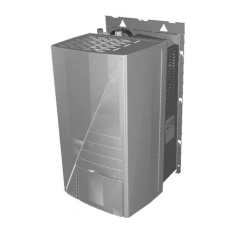
Nibe AXC 40 User guide

AXC 40
Installer Manual
Accessory card
LEK
IHB 2236-1
731176

S-series
4Important information
5General
6Common electrical connection
8Shunt controlled additional heat
13Step controlled additional heat
17Hot water comfort
22Ground water system
26Shunt controlled brine
30Hybrid connection - charge pumps
35Hybrid connection - reversing valves
39Pulse energy meter
41Technical data
71Contact information
3AXC 40
S
Table of Contents
S-series

Important information
SAFETY INFORMATION
This manual describes installation and service procedures
for implementation by specialists.
The manual must be left with the customer.
This appliance can be used by children
aged from 8 years and above and per-
sons with reduced physical, sensory or
mental capabilities or lack of experience
and knowledge if they have been given
supervision or instruction concerning use
of the appliance in a safe way and under-
stand the hazards involved. Children shall
not play with the appliance. Cleaning and
user maintenance shall not be made by
children without supervision.
This is an original manual. It may not be
translated without the approval of NIBE.
Rights to make any design or technical
modifications are reserved.
©NIBE 2022.
SYMBOLS
Explanation of symbols that may be present in this manual.
NOTE
This symbol indicates danger to person or machine.
Caution
This symbol indicates important information about
what you should consider when installing or servi-
cing the installation.
TIP
This symbol indicates tips on how to facilitate us-
ing the product.
MARKING
Explanation of symbols that may be present on the product’s
label(s).
Danger to person or machine.
!
Read the Installer Manual.
AXC 40 S-series | EN4
S
S-series

General
This accessory is used to enable connection and control of
the following accessory functions.
One AXC 40 is required for each function.
•shunt-controlled additional heat
•step-controlled additional heat
•control of circulation pump for hot water circulation
•controlling ground water pump
•shunt-controlled brine
•hybrid connection - charge pumps and reversing valves
•pulse energy meter
COMPATIBLE PRODUCTS
•S1155
•S1255
•VVM S320
•VVM S325
CONTENTS
Cable ties4 x
Heating pipe paste2 x
Insulation tape1 x
AXC module (AA25)1 x
Aluminium tape2 x
Temperature sensor2 x
COMPONENT LOCATION, AXC MODULE (AA25)
AA5-X4 AA5-S2
AA5-X2
AA5
AA25-X1
AA5-X9
AA25-FC1
ELECTRICAL COMPONENTS
Accessory cardAA5
DIP switchAA5-S2
Terminal block, inputsAA5-X2
Terminal block, communicationAA5-X4
Terminal block, outputsAA5-X9
AXC moduleAA25
Miniature circuit-breakerAA25-FC1
Terminal block, power supplyAA25-X1
Designations according to standard EN 81346-2.
5AXC 40 S-series | EN
S

Common electrical connection
NOTE
All electrical connections must be carried out by
an authorised electrician.
Electrical installation and wiring must be carried
out in accordance with national provisions.
The main product must be disconnected from the
power supply when installing AXC 40.
•To prevent interference, sensor cables to external connec-
tions must not be laid close to high voltage cables.
•The minimum area of communication and sensor cables
to external connections must be 0.5 mm² up to 50 m, for
example EKKX, LiYY or equivalent.
•AXC 40 must be installed via an isolator switch. The cable
area has to be dimensioned based on the fuse rating used.
•Mark the relevant electrical cabinet with a warning about
external voltage, in those cases where a component in
the cabinet has a separate supply.
•AXC 40 restarts after a power failure.
Electrical circuit diagrams are at the end of the chapter for
each connection option.
CABLE LOCK
Use a suitable tool to release/lock cables in terminal blocks.
LEK
1
1
2
2
3
3
1
2
3
3
4
1
2
LEK
1
1
2
2
3
3
1
2
3
3
4
1
2
1
2
MOUNTING
The AXC module (AA25) is a separate, electric control module
and must be mounted on a wall.
Caution
The screw type must be adapted to the surface
on which installation is taking place.
UN
Use all mounting points and mount the module upright, flat
against the wall.
Leave at least 100 mm of free space around the module to
allow access and make cable routing easier during installa-
tion and servicing.
NOTE
The installation must be carried out in such a way
that IP21 is satisfied.
OVERVIEW ACCESSORY BOARD (AA5)
ON
12345678
-X9
-X2
24 20212223 1516171819 1011121314 56789 1
1
N
L
PE
PE
1
2
3
4
5
6
7
8
2
3
4
5
6
7
8
9
234
-X8
-X4
-X10
-X1
AA5-X2 AA5-X9AA5-S2
AA5-X4
AXC 40 S-series | EN6
S

CONNECTING COMMUNICATION
AXC 40 contains an accessory board (AA5) that connects
directly to the main product’s PCB (terminal block AA2-X30).
If several accessories are to be connected, or are already
installed, the boards are connected in series.
Because there can be different connections for accessories
with accessory board (AA5), you should always read the in-
structions in the manual for the accessory that is to be in-
stalled.
B
A
GND
+12V
AA2-X30
1234
AA5-X4
1
2
3
4
5
6
7
8
A
B
GND
A
B
GND
AA5-X4
1
2
3
4
5
6
7
8
A
B
GND
A
B
GND
Main product
Accessory 1
Accessory 2
POWER CONNECTION
Connect the power supply cable to terminal block AA25-X1
as illustrated.
Tightening torque for earth cable: 0.5–0.6 Nm.
AA25-X1
N
L
ExterntProduktNamn
2
1
AA25 External
7AXC 40 S-series | EN
S

Shunt controlled additional heat
GENERAL
This function enables an external additional heater, e.g. an
electric boiler, wood boiler, pellet boiler, oil boiler, gas boiler
or district heating, to assist with the heating.
The heat pump/indoor module controls a shunt valve (EM1-
QN11) and a circulation pump (EM1-GP10) via AXC 40. If the
heat pump/indoor module cannot manage to maintain the
correct supply temperature (EB100-BT25), the additional
heat starts. When the temperature on the boiler sensor (EM1-
BT52) exceeds the set value, the heat pump transmits a
signal to the shunt (EM1-QN11) to open from the additional
heat. The shunt (EM1-QN11) is regulated so that the true
supply temperature agrees with the heat pump’s theoretic-
ally calculated set point value. When the heating demand
drops sufficiently so that additional heat is no longer re-
quired, the shunt (EM1-QN11) closes completely.
Factory-set minimum operating time for the boiler is 12
hours.
The function smart energy source can be selected if you
want to prioritise automatically between heat pump opera-
tion and additional heat versus the best price or environment-
al impact.
COMPATIBLE PRODUCTS
•S1155
•S1255
•VVM S320
•VVM S325
PIPE CONNECTIONS
The external circulation pump (EM1-GP10) is placed on the
supply line to the climate system after the temperature
sensor (AA35-BT25).
SHUNT VALVE
The shunt valve (EM1-QN11) must be placed on the supply
line to the climate system after the heat pump according to
the outline diagram.
AB
B
A
•Connect the supply line from the heat
pump to the external heat source via
the T-pipe to port B on the shunt valve
(closes on reduce signal).
•Connect the supply line to the climate
system from the shunt valve to the common port AB (al-
ways open)
•Connect the supply line from the external additional heat
to the shunt valve to port A (opens at reduced signal).
TEMPERATURE SENSOR
•Install the boiler sensor (EM1-BT52) in a suitable location
in the external additional heat.
•The external supply temperature sensor (EB100-BT25) is
installed on the supply line to the climate system, after
shunt valve (EM1-QN11).
LEK
LEK
E
Install the temperature sensor with cable ties with the heat
conducting paste and aluminium tape. Then insulate with
supplied insulation tape.
NOTE
To prevent interference, sensor cables to external
connections must not be laid close to high voltage
cables.
AXC 40 S-series | EN8
S

SYSTEM DIAGRAM
Caution
This is an outline diagram. Actual installations must
be planned according to applicable standards.
EXPLANATION
Mixing valve controlled additional heat, boilerEM1
AXC moduleAA25
Boiler sensorBT52
External heating medium pumpGP10
Mixing valve, additionQN11
Heat pumpEB100
External supply temperature sensorBT25
External return line sensorBT71
Miscellaneous
Non-return valveRM1
OUTLINE DIAGRAM WITH SHUNT-CONTROLLED
ADDITIONAL HEAT
-EM1-GP10
-EB100-BT25
-RM1
-EB100
-EB100-BT71
-EM1-AA25
-EM1-BT52
-EM1-QN11
-EM1
-EM1
ELECTRICAL CONNECTION
NOTE
Read section "Common electrical connection" for
instructions regarding electrical connection.
CONNECTION OF SENSORS AND EXTERNAL
BLOCKING
Boiler sensor (EM1-BT52)
Connect the sensor to AA5-X2:23-24.
Caution
Sensor cable splicing must fulfil IP54.
24 23 22 21 20 19 18 17 16 15 14 13
AA25
External
BT52
AA5-X2
External supply temperature sensor
(EB100-BT25)
To connect the external supply temperature sensor (BT25),
see the relevant product’s Installer Manual.
External return line sensor (EB100-BT71)
To connect the external return line sensor (BT71), see the
relevant product’s Installer Manual.
External blocking (optional)
A contact (NO) can be connected to AA5-X2:21-22 to block
the accessory. When the contact closes, the accessory is
blocked.
24 23 22 21 20 19 18 17 16 15 14 13
AA25
External
External blocking
AA5-X2
Caution
The relay outputs on the accessory board can have
a max load of 2 A (230 V) in total.
9AXC 40 S-series | EN
S

CONNECTION OF THE CIRCULATION PUMP
(EM1-GP10)
Connect the external heating medium pump (GP10) to AA5-
X9:8 (230 V), AA5-X9:7 (N) and X1:3 (PE).
1
2
3
4
5
6
7
8
9
AA5-X9
2
1
1
M
AA25-X1
External
AA25
GP10
CONNECTION OF THE SHUNT VALVE MOTOR
(EM1-QN11)
Connect the shunt motor (QN11) to AA5-X9:6 (230 V, open),
AA5-X9:5 (N) and AA5-X9:4 (230 V, close).
1
2
3
4
5
6
7
8
9
AA5-X9
1
M
External
AA25
Open SH +
N
SH -
Close
QN11
Connection of 0-10 V control of shunt motor
(EM1-QN11)
Connect a 2-core cable to AA5-X2:5 (0-10 V) and AA5-X2:6
(GND).
AA5-X2
0-10V
GND
7654
AA25
External
At 0 V the shunt is closed and at 10 V the shunt is open.
CONNECTION OF THE AUXILIARY RELAY FOR
ADDITIONAL HEATING
Connect the auxiliary relay for switching the additional heat
on and off to AA5-X9:2 (230 V) and AA5-X9:3 (N).
1
2
3
4
5
6
7
8
9
AA5-X9
L
N
A2 A1
Additional
heat
External auxiliary relay
External
AA25
DIP SWITCH
The DIP switch (S2) on the accessory board (AA5) must be
set as follows.
32
1
ON
476
58
AXC 40 S-series | EN10
S

PROGRAM SETTINGS
Activating AXC 40 can be performed via the start guide or
directly in the menu system.
The main product’s software must be the latest version.
START GUIDE
The start guide appears upon first start-up after heat pump
installation, but is also found in menu 7.7.
MENU SYSTEM
If you do not make all settings via the start guide or need to
change any of the settings, this can be done in the menu
system.
Menu 7.2.1 - Add/remove accessories
Here, you state which accessories are installed for the
compatible product.
To identify connected accessories automatically, select
"Search for accessories". It is also possible to select accessor-
ies manually from the list.
Menu 7.2.3 - Shunt-contr. add. heat(AXC)
Prioritised add. heat
Setting range: on/off
start additional heat
Setting range: -2000 – -30 DM
Minimum operating time
Setting range: 0 – 48 h
Lowest temperature
Setting range: 5 – 90 °C
Shunt amplification
Setting range: 0.1 –10.0
Shunt waiting time
Setting range: 10 – 300 s
Set when the addition is to start, the minimum run time and
the minimum temperature for external addition with shunt
here. External addition with shunt is for example a
wood/oil/gas/pellet boiler.
You can set shunt valve amplification and shunt valve
waiting time.
Selecting "Prioritised add. heat" uses the heat from the ex-
ternal additional heat instead of the heat pump. The shunt
valve is regulated as long as heat is available, otherwise the
shunt valve is closed.
See the accessory installation instructions for function de-
scription.
Menu 7.5.3 - Forced control
Here you can force control the various components in the
installation. The most important safety functions remain
active however.
NOTE
Forced control is only intended to be used for
troubleshooting purposes. Using the function in
any other way may cause damage to the compon-
ents in your installation.
Menu 4.6 -Smart Energy Source™
NOTE
Smart Energy Source™ requires external additional
heat.
Smart Energy Source™
Alternative: on/off
Control method
Alternatives: Price per kWh / CO2
If Smart Energy Source™ is activated, AXC 40 prioritises
how/to what extent each docked energy source will be used.
Here, you can select whether the system will use the energy
source that is cheapest at the time or the one that is most
carbon dioxide neutral at the time.
Caution
Your choices in this menu affect menu 4.7 - Energy
price.
Caution
Also see the Installer Manual for the main product.
11AXC 40 S-series | EN
S

ELECTRICAL CIRCUIT DIAGRAM
WIRING DIAGRAM SHUNT CONTROL
ELSCHEMA SHUNTSTYRD
051055 8
AXC 40 S-series | EN12
S

Step controlled additional heat
GENERAL
This function enables an external additional heater, e.g. an
electric boiler, to aid with heating.
With AXC 40, three potential-free relays can be used for
additional heat control, which then gives max. 3 linear or 7
binary steps.
The flow through the additional heat is ensured by the ex-
ternal circulation pump (EB1-GP10).
COMPATIBLE PRODUCTS
•S1155
•S1255
•VVM S320
•VVM S325
PIPE CONNECTIONS
The external circulation pump (EM1-GP10) is placed on the
supply line to the climate system after the temperature
sensor (AA35-BT25).
If the climate system’s flow exceeds the maximum recom-
mended flow for the electric boiler, a bypass must be in-
stalled so that only a partial flow passes through the electric
boiler.
TEMPERATURE SENSOR
•The external supply temperature sensor (EB100-BT25) is
installed on the supply line to the climate system, after
the additional heat.
LEK
LEK
E
Install the temperature sensor with cable ties with the heat
conducting paste and aluminium tape. Then insulate with
supplied insulation tape.
NOTE
To prevent interference, sensor cables to external
connections must not be laid close to high voltage
cables.
SYSTEM DIAGRAM
Caution
This is an outline diagram. Actual installations must
be planned according to applicable standards.
EXPLANATION
Step controlled additional heatEB1
AXC moduleAA25
External heating medium pumpGP10
Heat pumpEB100
External supply temperature sensorBT25
External return line sensorBT71
Miscellaneous
Shut-off valveQM42-43
Trim valveRN1
Non-return valveRM1
OUTLINE DIAGRAM WITH STEP-CONTROLLED
ADDITIONAL HEAT
-EB1-GP10
-EB100-BT25
-EB100
-RN1
-QM42
-QM43
-RM1
-EB100-BT71
-EB1-AA25
-EB1
-EB1
13AXC 40 S-series | EN
S

ELECTRICAL CONNECTION
NOTE
Read section "Common electrical connection" for
instructions regarding electrical connection.
CONNECTION OF SENSORS AND EXTERNAL
BLOCKING
External supply temperature sensor
(EB100-BT25)
To connect the external supply temperature sensor (BT25),
see the relevant product’s Installer Manual.
External return line sensor (EB100-BT71)
To connect the external return line sensor (BT71), see the
relevant product’s Installer Manual.
External blocking (optional)
A contact (NO) can be connected to AA5-X2:23-24 to allow
the function to be blocked. When the contact closes, the
function is blocked.
24 23 22 21 20 19 18 17 16 15 14 13
AA25
External
External blocking
AA5-X2
Caution
The relay outputs on the accessory board can have
a max load of 2 A (230 V) in total.
CONNECTING HEATING MEDIUM PUMP
(EB1-GP10)
Connect the external heating medium pump (GP10) to AA5-
X9:8 (230 V), AA5-X9:7 (N) and X1:3 (PE).
1
2
3
4
5
6
7
8
9
AA5-X9
2
1
1
M
AA25-X1
External
AA25
GP10
CONNECTION OF RELAYS
Connecting additional step
Connect step 1 to AA5-X9:1 and 2.
Connect step 2 to AA5-X9:3 and 4.
Connect step 3 to AA5-X9:5 and 6.
AA5-X9
ExterntProduktnamn
Steg 1
Steg 2
Steg 3
A2A1
A2
A1
A2A1
1
2
3
4
5
6
7
AA5-X9
AXC40 External
Step 1
Step 3
Step 2
Connection of 0-10 V control of additional heat
step
Connect a 2-core cable to AA5-X2:5 (0-10 V) and AA5-X2:6
(GND).
AA5-X2
0-10V
GND
7654
AA25
External
0 V = 0 steps and 10 V = max. number of set steps.
DIP SWITCH
The DIP switch (S2) on the accessory board (AA5) must be
set as follows.
32
1
ON
476
58
AXC 40 S-series | EN14
S

PROGRAM SETTINGS
Activating AXC 40 can be performed via the start guide or
directly in the menu system.
The main product’s software must be the latest version.
START GUIDE
The start guide appears upon first start-up after heat pump
installation, but is also found in menu 7.7.
MENU SYSTEM
If you do not make all settings via the start guide or need to
change any of the settings, this can be done in the menu
system.
Menu 7.2.1 - Add/remove accessories
Here, you state which accessories are installed for the
compatible product.
To identify connected accessories automatically, select
"Search for accessories". It is also possible to select accessor-
ies manually from the list.
Menu 7.2.6 - Step-control add. heat(AXC)
Relative DM start additional heat
Setting range: -2000 – -30 DM
Diff. between add heat steps
Setting range: 0 – 1,000 DM
Max step
Setting range
(binary stepping deactivated): 0 – 3
Setting range
(binary stepping activated): 0 – 7
Binary stepping
Setting range: on/off
Make settings for step controlled addition here. Step con-
trolled addition is for example an external electric boiler.
It is possible, for example, to select when the additional heat
is to start, to set the maximum number of permitted steps
and whether binary stepping is to be used.
When binary stepping is deactivated (off), the settings refer
to linear stepping.
See the accessory installation instructions for function de-
scription.
Menu 7.5.3 - Forced control
Here you can force control the various components in the
installation. The most important safety functions remain
active however.
NOTE
Forced control is only intended to be used for
troubleshooting purposes. Using the function in
any other way may cause damage to the compon-
ents in your installation.
Caution
Also see the Installer Manual for the main product.
15AXC 40 S-series | EN
S

ELECTRICAL CIRCUIT DIAGRAM
WIR. DIAGRAM STEP CONTROLLED
ELSCHEMA STEGSTYRD TILLSATS
051056 8
AXC 40 S-series | EN16
S

Hot water comfort
GENERAL
This function provides the opportunity to control additional
heat in the tank, mixing valve and hot water circulation.
ADDITIONAL HEAT IN TANK
If an immersion heater is installed in the tank, it can be per-
mitted to produce hot water at the same time as the heat
pump prioritises heating or cooling.
MIXING VALVE
A temperature sensor reads the temperature of the outgoing
hot water to the domestic hot water and adjusts the mixing
valve from the water heater until the set temperature has
been reached.
HOT WATER CIRCULATION (HWC)
One pump can be controlled for the circulation of the hot
water during selectable periods.
COMPATIBLE PRODUCTS
•S1155
•S1255
•VVM S320
•VVM S325
PIPE CONNECTIONS
MIXING VALVE
The mixer valve (QZ1-FQ3) must be placed on the outgoing
hot water line from the water heater according to the outline
diagram.
AB
A
B
•Connect the incoming cold water via
the T-pipe to port B on the mixer valve
(closes at signal).
•Connect the mixed water to the domest-
ic hot water taps from the mixer valve
to the common port AB (always open).
•Connect the outgoing hot water from the water heater to
the mixer valve to port A (opens on signal)
TEMPERATURE SENSOR
•Temperature sensor, outgoing hot water (QZ1-BT70), is
installed as close to the mixing valve (QZ1-FQ3) as pos-
sible.
LEK
LEK
E
Install the temperature sensor with cable ties with the heat
conducting paste and aluminium tape. Then insulate with
supplied insulation tape.
NOTE
To prevent interference, sensor cables to external
connections must not be laid close to high voltage
cables.
SYSTEM DIAGRAM
EXPLANATION
Caution
This is an outline diagram. Actual installations must
be planned according to applicable standards.
Hot water comfortQZ1
AXC moduleAA25
Hot water circulation pumpGP11
Mixer valve, hot waterFQ3
Trim valveRN1
Non-return valveRM1
Flow line sensorBT70
Return line sensor, hot waterBT82
Temperature sensor, hot water heaterBT83
Water heaterCP1
Additional water heaterCP2
Heat pumpEB100
Temperature sensor, hot waterBT6
Temperature sensor, hot water topBT7
OUTLINE DIAGRAM WITH ADDITIONAL WATER
HEATER, HWC AND ELECTRONIC MIXING VALVE
-CP2
-CP1
-EB100
-QZ1-BT83
-EB100-BT7
-EB100-BT6
-QZ1-AA25
-QZ1-BT70-QZ1-FQ3
-QZ1-GP11-QZ1-RM1
-QZ1
-QZ1-RN1
-BT82
17AXC 40 S-series | EN
S

ELECTRICAL CONNECTION
NOTE
Read section "Common electrical connection" for
instructions regarding electrical connection.
CONNECTION OF SENSORS AND EXTERNAL
BLOCKING
Hot water sensor, supply line (QZ1-BT70)
Connect the sensor to AA5-X2:23-24.
24 23 22 21 20 19 18 17 16 15 14 13
AA25
External
BT70
AA5-X2
Temperature sensor, hot water comfort,
return line (QZ1-BT82)
Connect the sensor to AA5-X2:17-18.
24 23 22 21 20 19 18 17 16 15 14 13
AA25
External
BT82
AA5-X2
Temperature sensor, hot water heater
(QZ1-BT83)
Connect the sensor to AA5-X2:19-20.
24 23 22 21 20 19 18 17 16 15 14 13
AA25
External
BT83
AA5-X2
External blocking
A contact (NO) can be connected to AA5-X2:21-22 to block
the accessory. When the contact closes, the accessory is
blocked.
24 23 22 21 20 19 18 17 16 15 14 13
AA25
External
External blocking
AA5-X2
External blocking, hot water circulation pump
(QZ1-GP11)
A contact (NO) can be connected to AA5-X2:15-16 to allow
the function to be blocked. When the contact closes, the
function is blocked.
24 23 22 21 20 19 18 17 16 15 14 13
AA25
External
AA5-X2
External blocking
Caution
The relay outputs on the accessory board can have
a max load of 2 A (230 V) in total.
CONNECTION OF THE HOT WATER
CIRCULATION PUMP (QZ1-GP11)
Connect the circulation pump (GP11) to AA5-X9:8 (230 V),
AA5-X9:7 (N) and X1:.
1
2
3
4
5
6
7
8
9
AA5-X9
2
1
1
M
AA25-X1
External
AA25
GP11
AXC 40 S-series | EN18
S
CONNECTION OF THE MIXER VALVE (QZ1-FQ3)
Connect the mixing valve motor (FQ3) to AA5-X9:6 (230 V,
open), AA5-X9:5 (N) and AA5-X9:4 (230 V, close).
1
2
3
4
5
6
7
8
9
AA5-X9
1
M
External
AA25
FQ3
Open
Close
CONNECTION OF AUXILIARY RELAY FOR
ADDITIONAL HEAT IN TANK
Connect the auxiliary relay for switching the additional heat
on and off to AA5-X9:2 (230 V) and AA5-X9:1 (N).
1
2
3
4
5
6
7
8
9
AA5-X9
L
N
A2 A1
Extra
hot water
External auxiliary relay
AA25 External
DIP SWITCH
The DIP switch (S2) on the accessory board (AA5) must be
set as follows.
32
1
ON
476
58
PROGRAM SETTINGS
Activating AXC 40 can be performed via the start guide or
directly in the menu system.
The main product’s software must be the latest version.
START GUIDE
The start guide appears upon first start-up after heat pump
installation, but is also found in menu 7.7.
MENU SYSTEM
If you do not make all settings via the start guide or need to
change any of the settings, this can be done in the menu
system.
Menu 7.2.1 - Add/remove accessories
Here, you state which accessories are installed for the
compatible product.
To identify connected accessories automatically, select
"Search for accessories". It is also possible to select accessor-
ies manually from the list.
Menu 2.5 - Hot water circulation
Operating time
Setting range: 1 – 60 min
Downtime
Setting range: 0 – 60 min
Period
Active days
Setting range: Monday – Sunday
Start time
Setting range: 00:00 – 23:59
Stop time
Setting range: 00:00 – 23:59
Set hot water circulation for up to five periods per day here.
During the set periods, the hot water circulation pump will
run according to the settings above.
"Operating time" decide how long the hot water circulation
pump must run per operating instance.
"Downtime" decide how long the hot water circulation pump
must be stationary between operating instances.
"Period" Here, you set the period of time during which the
hot water circulation pump will run, by selecting Active days,
Start time and Stop time.
NOTE
Hot water circulation is activated in menu 7.4
"Selectable in/outputs" or 7.2.8 "Hot water comfort
(AXC)".
19AXC 40 S-series | EN
S

Menu 7.2.8 - Hot water comfort (AXC)
Activating immersion heater.
Setting range: on/off
Activ. imm heater in heating oper
Setting range: on/off
Activating mixing valve
Setting range: on/off
Outgoing hot water
Setting range: 40 - 65 °C
Shunt amplification
Setting range: 0.1 – 10.0
Shunt waiting time
Setting range: 10 – 300 s
Make settings for the hot water comfort here.
Activating immersion heater.: The immersion heater is activ-
ated here, if installed in the water heater.
Activ. imm heater in heating oper: Activate here whether
the immersion heater in the tank (requires the above altern-
ative to be activated) is to be permitted to charge hot water,
if the compressors in the heat pump are prioritising heating.
Activating mixing valve: Activated if mixer valve is installed
and it is to be controlled from AXC 40. When the option is
active, you can set the outgoing hot water temperature,
shunt amplification and shunt waiting time for the mixer
valve.
Outgoing hot water: Here, you can set the temperature at
which the mixer valve is to restrict hot water from the water
heater.
Menu 7.5.3 - Forced control
Here you can force control the various components in the
installation. The most important safety functions remain
active however.
NOTE
Forced control is only intended to be used for
troubleshooting purposes. Using the function in
any other way may cause damage to the compon-
ents in your installation.
Caution
Also see the Installer Manual for the main product.
AXC 40 S-series | EN20
S
Other manuals for AXC 40
4
Table of contents
Other Nibe Heat Pump Accessories manuals