Nibe DEH 40 User guide

LEK
DEH40/41
Installatörshandbok DEH40/41
SE
Installer manual DEH40/41
GB
Installateurhandbuch DEH40/41
DE
IHB 1119-1
031583


Allmänt
OBS!
Denna symbol betyder fara för maskin eller
människa.
TÄNK PÅ!
Vid denna symbol finns viktig information om
vad du ska tänka på när du sköter din anlägg-
ning.
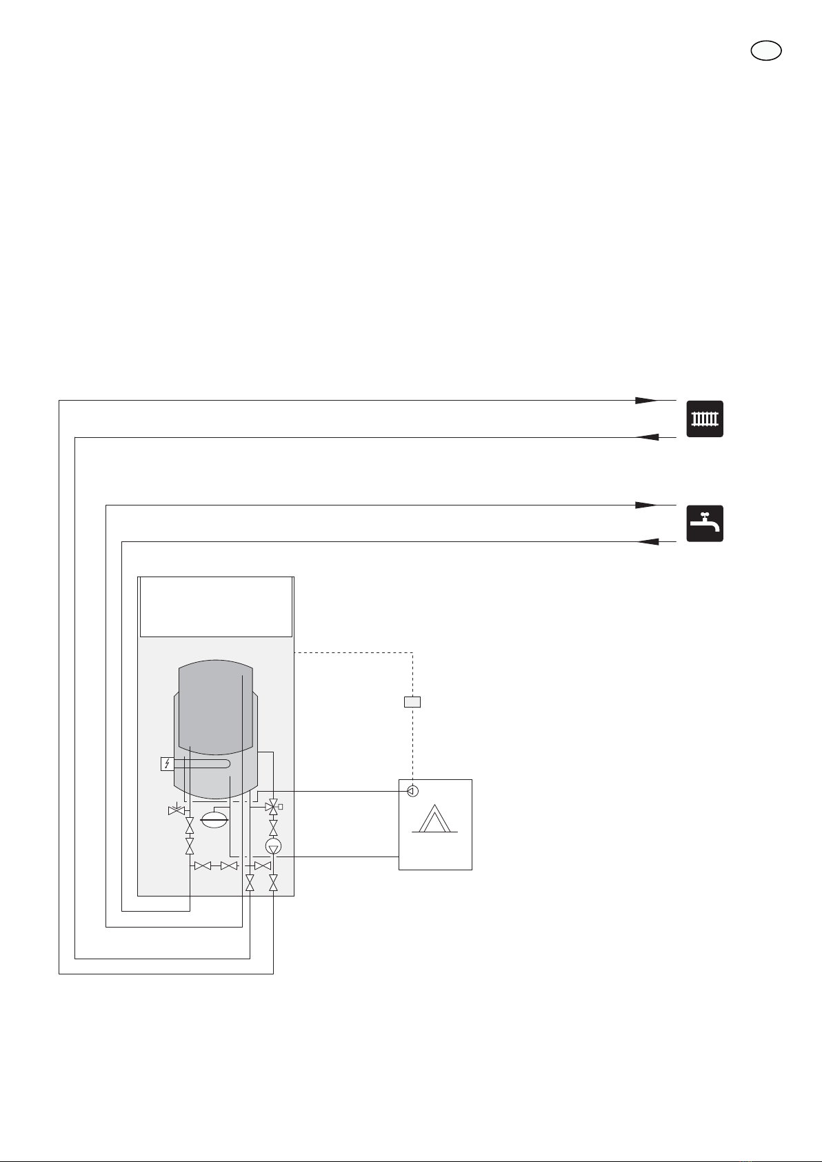
Detta tillbehör används till F370/F470 för att möjliggöra
inkoppling och styrning av externa värmekällor enligt
nedan:
႑DEH40:
႑Vedpanna
႑Oljepanna
႑Multifunktionstank
႑DEH41:
႑Gaspanna
Värmepumpen ventilerar byggnaden samt återvinner
värme ur ventilationsluften. Värmen används för uppvärm-
ning av byggnaden samt beredning av tappvarmvatten.
Normalt sker extra effekttillskott via värmepumpens elpa-
tron i de fall värmepumpens effekt inte är tillräcklig.
Med ovanstående alternativ sker detta effekttillskott
istället med hjälp av externa värmekällor. Om effekt inte
finns tillgänglig i den externa värmekällan kopplas elpa-
tronen i värmepumpen automatiskt in.
För att kunna docka till en extern värmekälla måste vär-
mepumpen kompletteras med två stycken dockningsrör,
vilka ingår i dockningssats DEH40/41.
OBS!
Då detta tillbehör är installerat och aktiverat be-
gränsas temperaturen i värmepumpens kärl till
ca 60 °C. Därför skall inte temperaturinställning-
ar avseende varmvatten eller värme över 60 °C
göras.
Innehåll
Rak koppling1st
T-rörskoppling1st
Laddomat typ N inkl cirkulationspump (endast DEH
40)
1st
Elkoppling tillbehör1st
Dockningsrör1st
Returrör1st
Temperaturgivare1st
Komponentplacering
LEK
AA5-X4
AA5-S2
AA5-X2 AA5-X9 X1
FA1
AA5-F1AA5
Elkomponenter
AutomatsäkringFA1
Anslutningsplint, spänningsmatningX1
TillbehörskortAA5
Anslutningsplint, givare och extern blocke-
ring
AA5-X2
Anslutningsplint, kommunikationAA5-X4
Anslutningsplint, cirkulationspump, shunt
och hjälprelä
AA5-X9
DIP-switchAA5-S2
FinsäkringAA5-F1
Beteckningar i komponentplacering enligt standard IEC
81346-1 och 81346-2.
3
Svenska, Installatörshandbok - DEH40/41
SE

Röranslutningar
För att förbereda F370/F470 för en extern värmekälla
behöver man bifogad rörsats bestående av två PEX-rör
med tillhörande rak klämringskoppling (dockningsrör)
och en T-rörskoppling (returrör).
Vid nyinstallation, gå direkt till punkt 6.
1. Ställ värmepumpens strömställare i läge ”0” och tag
bort frontluckan.
2. Stäng av avstängningsventilen för framledning i radi-
atorkretsen (QM31).
3. Stäng av avstängningsventilen för returledning i radi-
atorkretsen (QM32).
4. Släpp ut trycket i pannan genom att öppna säkerhets-
ventilen (FL2) försiktigt. (Ratten vrids moturs för att
öppna.)
5. Töm pannan genom (FL2), ställ avluftningsventilen
(QM20) i öppet läge för lufttillförsel.
6. Plocka bort befintlig koppling (XL8) och montera dit
medföljande dockningsrör, samt därefter medföljande
rak koppling.
7. Plocka bort befintlig vinkelkoppling (se bild nedan)
och montera dit medföljande returrör, samt därefter
medföljande T-rörskoppling.
8. Anslut inkommande rör från den externa värmekällan
till den lediga anslutningen i dockningsröret (A) och
returledningen till den lediga anslutningen i T-
rörskopplingen (B).
LEK
40 40)/ 40
;/
9LQNHONRSSOLQJHQ HUV¦WWV
AB
4
SE

Elinkopplingar
OBS!
All elektrisk inkoppling skall ske av behörig
elektriker.
Elektrisk installation och ledningsdragning skall
utföras enligt gällande bestämmelser.
Värmepumpen ska vara spänningslös vid instal-
lation av DEH40/41.
Elschema finns i slutet av denna Installatörshandbok.
Anslutning av matning
Anslut spänningsmatningen till plint X1 enligt bild.
3
2
1N
230V 50Hz-X1
L
PE
$SSDUDWO§GD ([WHUQW
Anslutning av kommunikation
Detta tillbehör innehåller ett tillbehörskort (AA5) som ska
anslutas direkt till värmepumpen på ingångskortet (plint
AA3-X4).
Om flera tillbehör ska anslutas eller redan finns installera-
de måste nedanstående instruktion följas.
Det första tillbehörskortet ska anslutas direkt till värme-
pumpens plint AA3-X4. De efterföljande korten ansluts
i serie med föregående kort.
Använd kabeltyp LiYY, EKKX eller likvärdig.
1
2
3
4
5
6
7
8
AA5-X4
15
A
B
GND
A
B
GND
A
B
GND
A
B
GND
A
B
GND
14
13
AA3-X4
1
2
3
4
5
6
7
8
AA5-X4
7LOOEHK¸UVNRUW
7LOOEHK¸UVNRUW
ON
12345678
-X9
-X2
24 20212223 1516171819 1011121314 567891
1
N
L
PE
PE
1
2
3
4
5
6
7
8
2
3
4
5
6
7
8
9
234
-X8
-X4
-X10
-X1
$$;
ON
12345678
-X9
-X2
24 20212223 1516171819 1011121314 567891
1
N
L
PE
PE
1
2
3
4
5
6
7
8
2
3
4
5
6
7
8
9
234
-X8
-X4
-X10
-X1
$$;
(%
))
$$;
5
SE

Anslutning av givare
Använd kabeltyp LiYY, EKKX eller likvärdig.
Givare (BT52)
Anslut givaren till AA5-X2:21-22.
TÄNK PÅ!
Skarvning av givarkabeln ska uppfylla IP54.
N
2345678
-X2
24 20212223 1
7
1819
-X8
$$
$
SSDUDWO§GD
([WHUQW
%7
Anslutning av cirkulationspump laddning
(GP15)
Anslut cirkulationspumpen (GP15) till AA5-X9:6 (230 V),
AA5-X9:5 (N) och X1:PE.
-X9
1
N
L
PE
PE
2
3
4
5
6
7
8
9
-X10
-X1
L
N
PE
-AA5
Apparatlåda Externt
GP15
Anslutning av styrning gaspanna
Anslut styrningen av gaspanna till AA5-X9:8 och X10.
Innan inkoppling skall frånskiljare avlägsnas från de båda
plintarna på X10.
-X9
1
N
L
PE
PE
2
3
4
5
6
7
8
9
-X10
-X1
2
1
-AA5
Apparatlåda Externt
Gaspanna
Extern blockering
En kontakt (NO) kan anslutas till AA5-X2:23-24 för att
kunna blockera tillbehöret. När kontakten sluts blockeras
tillbehöret.
24 20212223 171819
'(+
([WHUQW
$$;
([WHUQ EORFNHULQJ
$$;
ON
12345678
-X9
-X2
24 20212223 1516171819 1011121314 567891
1
N
L
PE
PE
1
2
3
4
5
6
7
8
2
3
4
5
6
7
8
9
234
-X8
-X4
-X10
-X1
6
SE

Systemprinciper
Förklaring
TillbehörskortAA5
KontrollenhetAA25
Temperaturgivare, värmebärare framBT52
TemperaturgivareBT54
ExpansionskärlCM5
AckumulatortankCP1
VärmepumpEB100
Olje-, gas-, pellets-, eller vedpannaEM1
SolpanelEP8
SäkerhetsventilFL7
LaddpumpGP15
CirkulationspumpGP19
Pumpstation SPS 10, SPS 20GP30
Pumpstation MCU 10GP31
ReglerventilQN50
BackventilRM5
Dockning vedpanna
Vid dockning av vedpanna/ackumulator till värmepumpen
måste tillses att inkommande vattentemperatur från
vedpanna/ackumulator till värmepumpen inte överstiger
60 °C.
Detta åstadkoms lämpligen genom att montera in en
temperaturbegränsarutrustning ”Laddomat typ N”, vilken
ingår i dockningssats DEH40. Det är också viktigt att
laddningsflödet inte överstiger 800 l/h då detta, såväl
som hög temperatur, påverkar värmepumpsdriften nega-
tivt.
Den i principschemat inritade utrustningen ”Laddomat
21” förhindrar att kallt ackumulatorvatten förs in i ved-
pannan med därpå följande kondensrisk. Denna utrust-
ning säljs ej av NIBE.
Elpatronstyrningen i värmepumpen skall nu istället styra
cirkulationspumpen mellan ackumulatorn och värmepum-
pen. Detta innebär att symbolen för elpatron visas i dis-
playen när tillsatseffektbehov föreligger.
-EB100
-QN50
-GP15
-AA5
-GP31
-RM5
-CP1 -BT52 -CM5
-FL7
-EM1
Laddomat 21
7
SE

Dockning oljepanna
Vid dockning av oljepanna till värmepumpen måste tillses
att inkommande vattentemperatur från oljepannan till
värmepumpen inte överstiger 60 °C.
Detta åstadkoms lämpligen genom att montera in tempe-
raturbegränsarutrustning ”Laddomat typ N”, vilken ingår
i dockningssats DEH40. Det är också viktigt att laddnings-
flödet inte överstiger 800 l/h då detta såväl som hög
temperatur påverkar värmepumpsdriften negativt.
Elpatronstyrningen i värmepumpen skall nu istället styra
cirkulationspumpen mellan oljepannan och värmepum-
pen. Detta innebär att symbolen för elpatron visas i dis-
playen när tillsatseffektbehov föreligger.
-EB100
-QN50
-GP15
-AA5
-GP19
-RM5
-BT52
-CM5
-FL7
-EM1
8
SE

Dockning gaspanna
Vid dockning av gaspanna till värmepumpen måste tillses
att inkommande vattentemperatur från gaspannan till
värmepumpen inte överstiger 60 °C.
Ställ därför gaspannans termostat på 60 °C. Det är också
viktigt att laddningsflödet inte överstiger 800 l/h då detta,
såväl som hög temperatur, påverkar värmepumpsdriften
negativt.
Elpatronstyrningen i värmepumpen skall nu istället styra
cirkulationspumpen i gaspannan. Detta innebär att sym-
bolen för elpatron visas i displayen när tillsatseffektbehov
föreligger.
-EB100
-AA5
-EM1
9
SE

Dockning multifunktionstank
Med multifunktionstank menas här en ackumulatortank
vars vatten värms upp från olika värmekällor, exempelvis
pelletskamin och solfångare.
Det måste tillses att inkommande vattentemperatur från
tank till värmepump inte överskrider 60 °C. Detta åstad-
koms lämpligen genom att montera in temperaturbegrän-
sarutrustning “Laddomat typ N” vilket ingår i docknings-
sats DEH40, respektive blandningsventil för tappvattnet.
Det är också viktigt att laddningsflödet inte överstiger
800 l/h då detta, såväl som hög temperatur, påverkar
värmepumpdriften negativt. Den i principschemat inritade
utrustningen “Laddomat 21” förhindrar att kallt ackumu-
latorvatten förs in i vedpannan (eller liknande) med därpå
följande kondensrisk. Denna utrustning säljs ej av NIBE.
Elpatronstyrningen i värmepumpen skall nu istället styra
cirkulationspumpen mellan ackumulatortanken och vär-
mepumpen. Detta innebär att indikering för elpatron visas
i displayen när tillsatseffektbehov föreligger.
-EB100
-QN50
-GP15
-AA5
-GP31
-RM5
-CP1
-BT54
-CM5
-FL7
-EM1
-BT52
-EP8
-AA25
Laddomat 21
10
SE

Aktivering av DEH40/41
Aktiveringen av F370/F470 kan göras via startguiden eller
direkt i menysystemet.
Startguiden
Startguiden visas vid första uppstart efter värmepumpsin-
stallationen, men finns även i meny 5.7.
Menysystemet
Om du inte aktiverar DEH40/41 via startguiden kan du
göra detta i menysystemet.
Meny 5.2 - systeminställningar
Aktivering/avaktivering av tillbehör.
TÄNK PÅ!
Se även Installatörshandboken för F370/F470.
TÄNK PÅ!
Värmepumpens mjukvara skall vara programva-
ruversion 1300 eller senare. Om så inte är fallet,
skall en uppdatering av mjukvaran göras. Upp-
datering finns tillgänglig på www.nibe.se/pro-
gramvara, alternativt på USB-minne.
11
SE

General
NOTE
This symbol indicates danger to machine or
person.
Caution
This symbol indicates important information
about what you should observe when maintain-
ing your installation.
This accessory is used for F370/F470 to enable connection
and control of external heat sources as follows:
႑DEH40:
႑Wood-fired boiler
႑Oil boiler
႑Multifunction tank
႑DEH41:
႑Gas boiler
The heat pump ventilates the building and recovers en-
ergy from the ventilation air. The heat is used to heat the
building and the hot water.
Normally additional output occurs via the heat pump’s
immersion heater in the event that the heat pump output
is not sufficient.
The above alternative gives this additional output using
external heat sources. If the power is not available in the
external heat source the immersion heater is automatically
engaged.
In order to dock an external heat source the heat pump
must be supplemented with two docking pipes, which
are included in the docking kits DEH40/41.
NOTE
When this accessory is installed and activated
the temperature in the heat pumps vessel is
limited to about 60 °C. Therefore, temperature
settings regarding hot water or heating must
not exceed 60 °C.
Contents
Straight connection1x
T-coupling1x
Laddomat type N incl. circulation pump (only DEH
40)
1x
Electrical connection accessory1x
Docking pipe1x
Return pipe1x
Temperature sensor1x
Component positions
LEK
AA5-X4
AA5-S2
AA5-X2 AA5-X9 X1
FA1
AA5-F1AA5
Electrical components
Miniature circuit-breakerFA1
Terminal block, power supplyX1
Accessory cardAA5
Terminal block, sensors and external
blocking
AA5-X2
Terminal block, communicationAA5-X4
Terminal block, circulation pump, mixing
valve and auxiliary relay
AA5-X9
DIP switchAA5-S2
Fine-wire fuseAA5-F1
Designations in component locations according to
standard IEC 81346-1 and 81346-2.
12
English, Installer manual - DEH40/41
GB

Pipe connections
To prepare F370/F470 for an external heat source, the
supplied pipe kit is required, which contains two PEX
pipes with accompanying straight compression ring
coupling (docking pipe) and a T-pipe coupling (return
pipe).
For new installation, go straight to point 6.
1. Set the heat pump switch to "0" and remove the
front cover.
2. Close the shut off valve for the flow line in the radi-
ator circuit (QM31).
3. Close the shut off valve for the return line in the ra-
diator circuit (QM32).
4. Release the pressure in the boiler by opening the
safety valve (FL2) carefully. (The knob is turned anti-
clockwise to open).
5. Drain the boiler through (FL2), set the vent valve
(QM20) in the open position for air supply.
6. Remove the existing connection (XL8) and install the
supplied docking pipe, and then the supplied straight
connection.
7. Remove the existing angled coupling (see image be-
low) and install the supplied return pipe, and then
the supplied T-pipe coupling.
8. Connect the incoming pipe from the external heat
source to the free connection in the docking pipe
(A), and the return pipe to the free connection in the
T-pipe coupling (B).
LEK
40 40)/ 40
;/
$
QJ
O
H
G
FRQQHF
W
RU
UHSODFHG
AB
13
GB

Electrical connections
NOTE
All electrical connections must be carried out by
an authorised electrician.
Electrical installation and wiring must be carried
out in accordance with the stipulations in force.
The heat pump must not be powered when in-
stalling DEH40/41.
The electrical circuit diagram is at the end of this Installer
manual.
Connecting the supply
Connect the power supply to terminal block X1 as illus-
trated.
3
2
1N
230V 50Hz-X1
L
PE
8QLW ER[ ([WHUQDO
Connecting communication
This accessory contains an accessories card (AA5) that
must be connected directly to the heat pump on the input
card (terminal block AA3-X4).
If several accessories are to be connected or are already
installed, the following instructions must be followed.
The first accessory card must be connected directly to the
heat pump's terminal block AA3-X4. The following cards
must be connected in series with the previous card.
Use cable type LiYY, EKKX or similar.
1
2
3
4
5
6
7
8
AA5-X4
15
A
B
GND
A
B
GND
A
B
GND
A
B
GND
A
B
GND
14
13
AA3-X4
1
2
3
4
5
6
7
8
AA5-X4
$FFHVVRU\ FDUG
$FFHVVRU\ FDUG
ON
12345678
-X9
-X2
24 20212223 1516171819 1011121314 567891
1
N
L
PE
PE
1
2
3
4
5
6
7
8
2
3
4
5
6
7
8
9
234
-X8
-X4
-X10
-X1
$$;
ON
12345678
-X9
-X2
24 20212223 1516171819 1011121314 567891
1
N
L
PE
PE
1
2
3
4
5
6
7
8
2
3
4
5
6
7
8
9
234
-X8
-X4
-X10
-X1
$$;
(%
))
$$;
14
GB

Connecting sensors
Use cable type LiYY, EKKX or similar.
Sensor (BT52)
Connect the sensor to AA5-X2:21-22.
Caution
Sensor cable splicing must fulfil IP54.
N
2345678
-X2
24 20212223 1
7
1819
-X8
$$
8QLW ER[
([WHUQDO
%7
Connecting circulation pump charging (GP15)
Connect the circulation pump (GP15) to AA5-X9:6 (230
V), AA5-X9:5 (N) and X1:PE.
-X9
1
N
L
PE
PE
2
3
4
5
6
7
8
9
-X10
-X1
L
N
PE
-AA5
Unit box External
GP15
Connecting gas boiler control
Connect gas boiler control to AA5-X9:8 and X10.
Prior to connection, remove the contact breaker from
both terminals on X10.
-X9
1
N
L
PE
PE
2
3
4
5
6
7
8
9
-X10
-X1
2
1
-AA5
Unit box External
Gas boiler
External blocking
A contact (NO) can be connected to AA5-X2:23-24 to
block the accessory. When the contact closes, the access-
ory is blocked.
24 20212223 171819
'(+
([WHUQDO
$$;
([WHUQDO EORFNLQJ
$$;
ON
12345678
-X9
-X2
24 20212223 1516171819 1011121314 567891
1
N
L
PE
PE
1
2
3
4
5
6
7
8
2
3
4
5
6
7
8
9
234
-X8
-X4
-X10
-X1
15
GB

System principles
Explanation
Accessory cardAA5
Control unitAA25
Temperature sensors, heating medium flowBT52
Temperature sensorBT54
Expansion vesselCM5
Accumulator tankCP1
Heat pumpEB100
Oil, gas, pellet or wood boilerEM1
Solar panelEP8
Safety valveFL7
Charge pumpGP15
Circulation pumpGP19
Pump station SPS 10, SPS 20GP30
Pump station MCU 10GP31
Control valveQN50
Non-return valveRM5
Docking wood boiler
When docking a wood boiler/accumulator to the heat
pump it must be ensured that the incoming water tem-
perature from the wood boiler/accumulator to the heat
pump does not exceed 60 °C.
This is most appropriately achieved by installing temper-
ature limiting equipment "Laddomat type N". which is
part of docking kit DEH40. It is also important that the
charge flow does not exceed 800 l/h otherwise this, as
well as the high temperature, can affect the heat pump
operation negatively.
The "Laddomat 21" in the outline diagram prevents cold
accumulator water from being transferred to the wood
boiler with the ensuing risks of condensation. This
equipment is not sold by NIBE.
The immersion heater control in the heat pump must in-
stead control the circulation pump between the accumu-
lator and the heat pump. This means that the symbol for
the immersion heater is shown in the display when there
is a need for additional output.
-EB100
-QN50
-GP15
-AA5
-GP31
-RM5
-CP1 -BT52 -CM5
-FL7
-EM1
Laddomat 21
16
GB

Docking oil boiler
When docking an oil boiler to the heat pump it must be
ensured that the incoming water temperature from the
oil boiler to the heat pump does not exceed 60 °C.
This is most appropriately achieved by installing temper-
ature limiting equipment "Laddomat type N". which is
part of docking kit DEH40. It is also important that the
charge flow does not exceed 800 l/h otherwise this, as
well as the high temperature, can affect the heat pump
operation negatively.
The immersion heater control in the heat pump must in-
stead control the circulation pump between the oil boiler
and the heat pump. This means that the symbol for the
immersion heater is shown in the display when there is
a need for additional output.
-EB100
-QN50
-GP15
-AA5
-GP19
-RM5
-BT52
-CM5
-FL7
-EM1
17
GB

Docking, gas boiler
When docking a gas boiler to the heat pump it must be
ensured that the incoming water temperature from the
gas boiler to the heat pump does not exceed 60 °C.
Set the gas boiler thermostat to 60 °C. It is also important
that the charge flow does not exceed 800 l/h otherwise
this, as well as the high temperature, can affect the heat
pump operation negatively.
The immersion heater control in the heat pump must in-
stead control the circulation pump in the gas boiler. This
means that the symbol for the immersion heater is shown
in the display when there is a need for additional output.
-EB100
-AA5
-EM1
18
GB

Docking multifunction tank
Multifunction tank means an accumulator tank whose
water is heated by different heat sources, for example
pellet stove and solar panels.
It must be ensured that the incoming water temperature
from the tank to the heat pump does not exceed 60 °C.
This is most appropriately achieved by installing temper-
ature limiting equipment "Laddomat type N". which is
part of docking kit DEH40, respectively mixing valve for
domestic water.
It is also important that the charge flow does not exceed
800 l/h otherwise this, as well as the high temperature,
can affect the heat pump operation negatively. The
"Laddomat 21" in the outline diagram prevents cold ac-
cumulator water from being transferred to the wood
boiler (or similar) with the ensuing risks of condensation.
This equipment is not sold by NIBE.
The immersion heater control in the heat pump must in-
stead control the circulation pump between the accumu-
lator tank and the heat pump. This means that the symbol
for the immersion heater is shown in the display when
there is a need for additional output.
-EB100
-QN50
-GP15
-AA5
-GP31
-RM5
-CP1
-BT54
-CM5
-FL7
-EM1
-BT52
-EP8
-AA25
Laddomat 21
19
GB

Activating DEH40/41
Activating F370/F470 can be performed via the start guide
or directly in the menu system.
Start guide
The start guide appears upon first start-up after heat
pump installation, but is also found in menu 5.7.
Menu system
If you do not activate DEH40/41 via the start guide, this
can be done in the menu system.
Menu 5.2 - system settings
Activating/deactivating of accessories.
Caution
Also see the Installer manual for F370/F470.
Caution
The heat pump software must be version 1300
or later. If it is not, perform a software update.
The update is available at www.nibe.se/program-
vara, alternatively on USB memory.
20
GB
This manual suits for next models
1
Table of contents
Languages:
Other Nibe Heat Pump Accessories manuals