NSK Surgic Pro User manual

OPERATION MANUAL
Please read this Operation Manual carefully
before use, and file for future reference.
Surgic Pro
Surgery System
OM-E0780E 001
2017.XX.XX 000 N

English
◆Intended to Use
Safety precautions prior to use
Package Contents
Control Unit and Foot Control
Installation
Setting
Operation
Protection Circuit
Error Code & Troubleshooting
Fuse Replacement
Maintenance
Sterilization
Contra Angle Handpieces and Accessories
Specification
Disposing Product
Symbols
EMC Information
Contents
1.
2.
3.
4.
5.
6.
7.
8.
9.
10.
11.
12.
13.
14.
15.
16.
2
4
5
7
10
12
16
16
18
18
19
20
20
20
21
21
◆Classification of equipment
• Type of protection against electric shock :
– Class l equipment
• Degree of protection against electric shock :
– Type BF applied part
• Method of sterilization or disinfection recommended by the manufacture :
– See 11. Sterilization
• Degree of protection against ingress of water as detailed in the current edition of IEC 60529 :
– Foot Control: IPX8 (Protected against the effects of continuous immersion in water)
• Degree of safety of application in the presence of a flammable anesthetic mixture with air or with oxygen or nitrous
oxide :
– Foot Control: Category AP Equipment
• Mode of operation :
– Intermittent operation
Thank you for purchasing the NSK Surgic Pro series surgical unit.
We recommend that prior to use, you carefully read this document regarding instructions for use, handling method, or
maintenance check so that you can carry on using the unit in the future. In addition, keep this operation manual in a
place where a user can refer to it at any given time.
Surgic Pro series is intended for use in dental oral surgery by qualified personnel.
English
Original Operatrion Manual
1

1. Safety precautions prior to use
Read Handpiece’s Operation manual carefully before use.
Classification Degree of Danger or Damage and Seriousness
WARNING Explains an instruction where personal injury or physical damage may occur.
CAUTION Explains an instruction where minor to medium injury or physical damage may occur.
NOTICE Explains an instruction that should be observed for safety reasons.
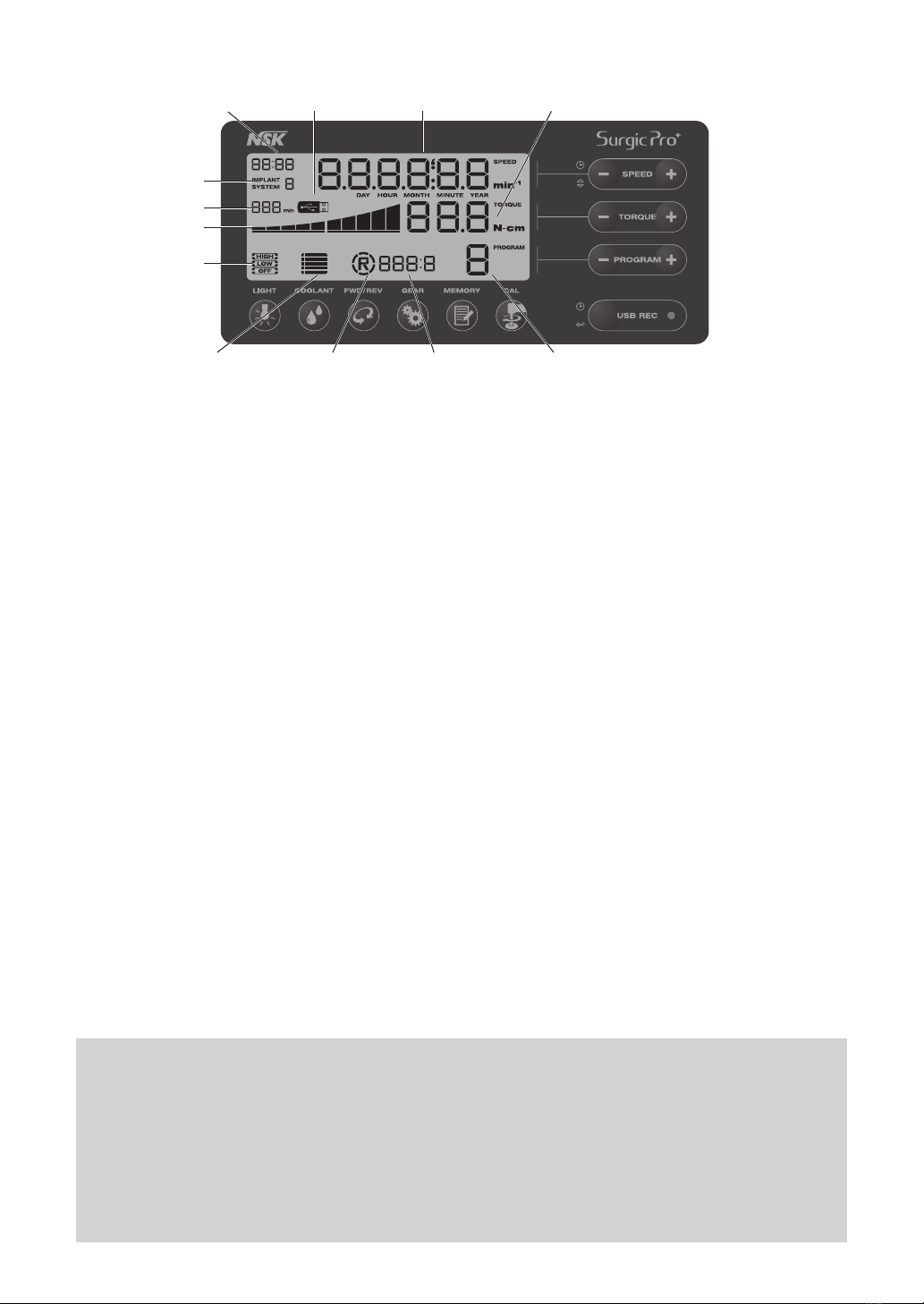
• The accuracy of the Torque Monitor depends on the high precision performance of the handpiece attached to the
micromotor. Real torque value may not otherwise be correctly displayed. To guarantee handpiece torque accuracy,
that matches the monitor display system, USE ONLY the NSK contra angle handpieces listed on “12. Contra Angle
Handpieces and Accessories”. When other handpice had connected, it may not output accurate torque which
indicated on handpiece.
• Surgic Pro series needs special precautions regarding EMC and needs to be installed and put into service according
to the EMC information. (Refer to 16. EMC Information)
• Portable and mobile RF (Radio Frequency) communications equipment can affect Surgic Pro series. Do not use RF
equipment outskirts for the product.
• The use of accessories, Motors and cables other than those specified, with the exception of Motors and cables sold
by the manufacturer of Surgic Pro series as replacement parts for internal components, may result in increased
EMISSIONS or decreased IMMUNITY of the Control Unit.
• Surgic Pro series should not be used adjacent to or stacked with other equipment and that if adjacent or stacked use
is necessary, the Control Unit should be observed to verify normal operation in the configuration in which it will be
used.
• When operating this system always consider the safety of the patient.
• Do not attempt to disassemble the Control Unit /Foot Control / Micromotor nor temper with the mechanism.
• Check for vibration, noise and overheating before use and if any abnormalities are found in use, stop using
immediately and contact dealer.
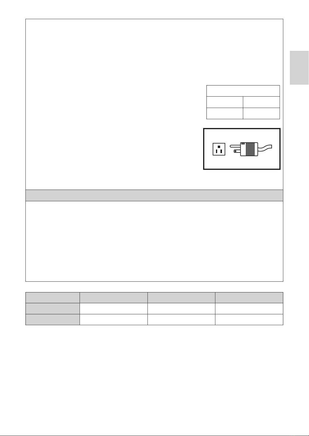
• Use an electrical outlet that is grounded.
• Do not drop, hit, or subject to excessive shock.
• Do not bend the Irrigation Tube while the irrigation pump is operating. It could cause tube breakage.
• Do not use bent, damaged or sub-standard burs or drill. The Shank could bend or brake.
• Do not exceed the recommended speed and torque.
• TO PREVENT ELECTRIC SHOCK Do not unplug the AC Power cord with wet hands.
• TO PREVENT ELECTRIC SHOCK Be sure to prevent water on the Control Unit.
• TO PREVENT ELECTRIC SHOCK Use an electrical outlet that is grounded.
• The system may present a possibility of malfunction when used in the presence of an electromagnetic interference
wave. Do not install the system in the vicinity of the device which emits magnetic waves. Turn off the Main Power
Switch of the Control Unit of this system when an ultrasonic oscillation device or an electrode knife is located in the
vicinity is used.
CAUTION
WARNING
2
Read these safety cautions thoroughly before use and operate the product properly.
These indicators are to allow you to use the product safely, prevent danger and harm to you and others. These are
classified by degree of danger, damage and seriousness. All indicators concern safety, be sure to follow them.
Cautions for handling and operation

English
No moisture condensation in the Control Unit.
Use at outside of these limits may cause malfunction.
Use
Store (Transportation)
Temperature
Between 0-40˚C (32-104˚F)
Between -10-50˚C (14-122˚F)
Humidity
Between 10-85% RH
Between 10-85%RH
Atmospheric pressure
Between 700-1060hPa
Between 500-1060 hPa
• After each Operation, be sure to lubricate and sterilize the handpiece as soon as it’s cleaned. Blood coagulation can
cause corrosion and rusting. However, do not lubricate the Micromotor. Oil could generate excessive heat and cause damage.
• The Control Unit can be cleaned with a moist cloth. Disconnect the power supply before cleaning. The Control Unit
and the Foot Control cannot be sterilized by any method.
• When the system is very frequently used, consider the maintenance of a small stock of replaceable parts.
• Do not disconnect the Motor Cord from the motor.
• Do not wipe with or, clean or immerse in, high acid water or sterilizing solutions.
• Follow the table below for the motion time of motor and handpiece. Continuous
use over a long time with high torque may cause the overheating of the
handpiece, which in turn may result in an accident.
• Applied parts for patient and/or operator is Handpiece.
• Do not fixate the eyes of LED light.
• If any abnormalities (dark, do not light on or flashing) are found for LED, stop
using the it immediately and contact dealer.
• Using the Micromotor with light ‘ON’ for more than 3 minutes continuously,
motor will become hot. (The maximum surface temperature might reach 45˚C
by the situation used) In such cases, stop using the Micromotor till the light part
cools down, or use the Micromotor without turning on the light.
• Grounding reliability can only be achieved when the equipment is connected to
an equipment receptacle marked "Hospital Only" or "Hospital Grade".
• For safety’s sake, install the Control Unit in a place where the AC POWER
Cord can be easily removed. (It is possible to disconnect the control unit from the power source by removing the AC
POWER Cord.)
• Turn off the Main Power Switch after each use.
• For service requirements and spare parts contact dealer.
• Use of NSK genuine pre-sterilized, disposable Irrigation Tube is recommended.
• Total recording time is about 100 minutes. (Surgic Pro+)
• Do not insert a USB flash drive during operation.
• Do not remove USB flash drive while LED lamp is on or blinking.
• Do not use data stored in USB flash drive for diagnostic purposes.
• Do not use a USB flash drive other than USB 2.0.
• This device is not guaranteed to work with all USB flash drive. It may not work with USB flash drive with security
functions or those requiring a great deal of electricity.
NOTICE
3
Operating Mode
Intermitternt Operation
ON
3 min.
OFF
10 min.
Power plug below is used in North America area.
Plug Type NEMA 5-15P (Hospital Grade Type)

2. Package Contents
* Handpiece will be attached suitable one (Applied part)
* USB flash drive not included.
*Figure shows Optic Motor and Optic Handpiece
171513
1 2 3 4 5
67 8
9
10
11 12 14
16
18
19
11
12
13
14
15
16
18
19
17
Quantity
1
1
1
5
1
1
1
1
2
7
Description
AC Power Cord
Foot Controller with Cord (2m)
Control Unit
Irrigation Tube
Coolant Solution Hanger Post
Optic Handpiece / Non-Optic Handpiece *
Optic Motor / Non-Optic Motor (With Motor Cord)
*
Y-Connector
Spare Fuse
Tube Holder
Item
No. Quantity
1
1
1
1
1
1
1
2
2
Description
Handpiece Stand
Internal Irrigation Nozzle
Nozzle Holder
Cleaning Wire
Calibration Bur
E-type Spray Nozzle
Protection Plug
O-ring (Protection Plug)
O-ring (Motor)
Item
No.
1
2
3
4
5
6
7
8
9
10
4

English
3. Control Unit and Foot Control
3-1 Keys on the Control Unit
Light Key
Select the light level. (OFF -> LOW->HIGH) Repeat press Key to cycle through light levels. (Default:HIGH)
Coolant Key
Use to select 6 levels of coolant solution flow from 0 to 5, repeat press Key to cycle through coolant flow levels.
FWD/REV Key
Use to select the direction of rotation. Press this Key once to change the rotational direction. (Once in Reverse the
Control Unit audibly warns with a ‘beep’)
GEAR Key
Use to set gear ratio of the attached handpiece before use. Repeat press this Key until the LCD display indicates the
correct gear ratio of the handpiece.
MEMORY Key
Use to memorize the program parameters set by the operator. Press & hold this Key for approx. 1 second to memorize
parameters. When beep sounds, the new program parameters have been memorized.
CAL Key
Use to activate calibration cycle of the handpiece before use.
SPEED Key (- +)
Use to set the Micromotor speed. Press [+] Key to increase, and [-] Key to decrease speed. When keep pushing the
key to change the speed quickly. (When the upper and lower speed limits are reached an audible alarm ‘beep’ is
sounded).
TORQUE Key (- +)
Use to set the torque range. Press [+] Key to increase and [-] Key to decrease torque range. When keep pushing the
key to change the torque range quickly. (When the upper and lower torque range limits are reached an audible alarm
‘beep’ is sounded). The torque range setting should be selected according to the attached handpiece gear ratio.
PROGRAM Key (- +)
Select the available programs. (1 to 8) Press [+] Key to ascend and [-] Key to descend program number. You will find
all program numbers sequentially by pressing Keys.
USB REC (Surgic Pro+ ONLY)
Press this Key to record the Surgic Pro series operation to USB flash drive.
A short push will save data being memorized to USB flash drive. A long push (about 2 seconds) will erase data saved
on the control unit memory.
(1)
(2)
(3)
(4)
(5)
(6)
(7)
(8)
(9)
(10)
Calibration Load
(1) Light Key
Motor Cord
Connector Socket
(7) SPEED Key
(8) TORQUE Key
(9) PROGRAM Key
(10) USB REC
Irrigation Pump
USB flash drive Socket
Coolant Solution
Hanger Post Holder
AC Power Cord
Connector socket
Fuse Holder
Main Power Switch
Foot Control Cord
Connector Socket
(2) Coolant Key
(3) FWD/REV Key
(4) GEAR Key
(5) MEMORY Key
(6) CAL Key
5
*The item which does not have number is explained in context.

3-2 LCD display on the Control Unit Console
Clock Display (Surgic Pro+ ONLY)
Clock display. Time is displayed using batteries installed in the Control Unit.
SPEED
Selected speed indication. Rotation speed is displayed during rotation. When rotation stops, the maximum rotation
speed set is displayed. Depressing Foot Control: Rotation speed of the motor displayed on the LCD (Assuming the
correct gear ratio is selected) Foot Control speed varies depending on how far foot is depressed. Without pressing
Foot Control: Max Rotation preset setting displayed on the LCD
IMPLANT SYSTEM
The number of the implant system being used is displayed. (1 to 8)
Memory Time (Surgic Pro+ ONLY)
Memory time remaining is displayed (Remain Time).
USB flash drive (Surgic Pro+ ONLY)
When USB flash drive is inserted, it is displayed on the LCD.
TORQUE Graph
Display the actual operating torque range. When all bars illuminate, the operating torque is at maximum. When bars
are half illuminated then the operating torque is approximately 50% of the preset torque.
TORQUE
Selected torque indication. When using the 1:1 direct drive or Speed increasing handpiece, the torque is not displayed.
(This function is appropriate for 2:1 reduction speed handpiece or more)
Light Level (For Optic ONLY)
Displays the selected light level; light levels are HIGH, LOW and OFF.
Coolant Level
Displays the selected coolant solution flow level; the selected Flow level is indicated by 0 to 5 levels of illuminated
indicators. No illumination indicates when the Coolant Solution Flow is off.
FWD/REV Direction
Displays the selected direction of handpiece rotation. When rotating, the circumference display rotates.
GEAR Ratio
Selected Gear Ratio of the handpiece.
PROGRAM Number
Selected Program Number indication. (1 to 8)
(A)
(B)
(C)
(D)
(E)
(F)
(G)
(H)
(I)
(J)
(K)
(L)
(A) Clock Display (B) SPEED
(C) IMPLANT SYSTEM
(D) Memory Time
(E) USB flash drive
(F) TORQUE Graph
(G) TORQUE
(H) Light Level
(I) Coolant Level (J) FWD/REV Direction (K) GEAR Ratio (L) PROGRAM Number
6
NOTICE • Right after turning on the power source, the clock may display “88:88/00:00” or the LCD of the USB
REC key may blink, but these are not malfunctions.
• When the power source is turned on, the device will return to its default settings. To save a setting,
see 6-1 Programming the Micromotor Operation. (Default: Implant system 1, Light HIGH, Coolant Flow
3, Rotation F, Gear Ratio 20:1, Program Number 1, Torque 20N•cm, Speed 800min-1)
•
When packed for shipping, etc., the clock will blink on “00:00” if the clock has not been set. See 5-1 Clock and
Date.
•
When the clock display blinks on “- -: - -,” the clock batteries have run out. Contact the retailer where device
was purchased.

English
3-3 Foot Control
Coolant Solution Flow Volume Button
Use to select 6 levels of coolant solution flow from 0 to 5; each level may be increased by one step pressing this
button. If you press this button in level 5, it returns to level 0.
PRG (Program) Button
Use to select the desired program number. Program numbers will always ascend each time this button is pressed and
released. To descend, press and hold for 1 second then release.
Speed Control Pedal
Use to start and stop the Micromotor and to control the speed during operation. The Micromotor operational speed is
directly proportional to the position of the foot control, up to the preset maximum.
Forward/Reverse Button
Use to change the rotational direction of the Micromotor. Push once to change the rotational direction.
(a)
(b)
(c)
(d)
(b) PRG (Program) Button
(c) Speed Control Pedal
Foot Control Cord and Plug
4. Installation
Align the [●] mark on the Motor Cord with [●] mark on the
Control Unit.
Push the Base of Motor Cord Plug into the socket until the
locking joint ‘clicks’ into place.
To disconnect the plug; pull back the Lock Joint, pull further
to disconnect the cord.
4-1 Connecting the Motor Cord
(a) Coolant Solution Flow
Volume Button
(d) Forward/Reverse Button
7
[●] mark
Lock Joint
Fig.1
CAUTION
• Install the cord/plug only power is OFF.

4-4 Connecting the AC Power Cord
Ensure the Pump Cover Lever is in the ‘OPEN’ position, with the Irrigation tube ‘Needle’ towards the backside of the
Control Unit. Position the stoppers of the tube assembly in to the Tube Guide securely. (Fig.4)
4-5 Installing the Irrigation Tube
Correctly align then insert the AC Power Cord into the
AC Power Cord Connector Socket at the back of the
Control Unit. (Fig.3)
4-2 Connecting the Handpiece
Push the handpiece on to the motor taking care to keep it in
alignment.
Twist the handpiece until it locks into position with a clicking sound.
1)
2)
Face the screw on the Foot Control Cord Plug downward
then insert the plug into the Foot Control Cord connector
socket on the Control Unit. Secure the plug by fastening
the Lock Nut. Refer Fig.3.
4-3 Connecting the Foot Control
<OPEN Position>
AC Power Cord Foot Control Cord Plug
Screw
Water flow direction
Pump Cover
Tube Guide
Fixed Position
Fixed Position
Fig.2
Fig.3
Fig.4
8
Stopper
Pump Cover Lever
CAUTION
• When using the Optic Surgic Pro micromotor (SGL70M), USE ONLY Optic contra-angle handpieces.
Non Optic handpieces may not precisely connect to the micromotor and it may malfunction when the
micromotor is under load.

English
After the tubes are correctly positioned, close the Pump Cover by
turning the Pump Cover Lever to the ‘CLOSE’ position. (180 degrees
counterclockwise) (Fig.6)
To remove, ‘OPEN’ the Pump Cover Lever then remove the tube.
<CLOSE Position>
Align
Fig.7
Tube Clamp
Bottle Cap
Irrigation
Tube Needle
Tube Cap
Fig.8 Fig.9 Fig.10
Fig.6
9
Mount the Coolant Solution Hanger Post onto the Holder on the Control
Unit. (Fig.7)
Close the Tube Clamp, between the Irrigation Tube Needle and the Irrigation Pump. (Fig.8)
Insert the Irrigation Tube Needle into the Bottle Cap. (Fig.9)
Open the Tube Cap to supply air into the bottle. (Fig.10)
Open the Tube Clamp.
1)
2)
3)
4)
4-7 Insertion of the Irrigation Tube
4-6 Mounting the Coolant Solution Hanger Post
CAUTION
CAUTION
Fig.5
• Make sure that the tube is securely
set on the rollers when closing
the Pump Cover. If the tube is not
correctly positioned on the Rollers
and the cover is closed, the tube
could be cut or sheared. (Fig.5)
• Do not mount the Irrigation Tube
except the person who specially
educated.
• Do not mount the Irrigation Tube
during Power is ON.
• Do not operate the Irrigation Pump if the tube is bent or the Tube Clamp is in the closed position. This
could cause the tube to burst or slip out of the bottle.

Irrigation Tube
Drill
Motor Cord
Irrigation Tube
Tube Holder
Fig.11
Fig.12
Fig.13
USB flash drive
Socket
10
4-8 Compatibility check of Internal Irrigation Nozzle/Drill
Internal irrigation nozzles accompanied with this product; is not necessarily fitted into all the drills on the market.
Follow the instructions given below for confirmation prior to use.
Failure to do so or to fit the Internal Irrigation Nozzle into drills may cause a leakage of saline solution, which will
result in problems such as rust or sudden stop of equipment during use.
* To mount the Drill, refer to attached Handpiece Operation Manual.
Instructions:
Attach a bottle of saline solution to the Control Unit.
Connect the Internal Irrigation Nozzle into the tip of the irrigation tube.
Insert the Internal Irrigation Nozzle into the drill from the back. (Fig.11)
Purge at “Maximum” for 5 seconds.
1)
2)
3)
4)
Points to be checked:
4-9 Irrigation Nozzle Attachment
X-SG20L and SG20 has 3 irrigation methods available depending on tool and application; External, Internal or both,
for installation detail, refer to the attached handpiece Operation Manual.
4-10 Attaching the Tube Holder
Use the Motor Cord as a strain relief for the ‘Irrigation Tube’. It is
easier to insert Motor Cord first, then the Irrigation Tube. (Fig.12)
4-11 USB flash drive (Not supplied) (Surgic Pro+ONLY)
Open the Insertion Opening Cover on the Control Unit side.
Completely insert the USB flash drive. The USB mark will appear
on the LCD DISPLAY when USB flash drive is recognized by the
device. (Fig.13)
1)
2)
5. Setting
5-1 Clock and Date
•Cleanliness of the saline solution coming out from the drill; if solution is colored there could be rust inside of the
drill. If so renew the drill.
•Water Flow; if the flow is low and/or the flow from the drill is asymmetric, renew the drill.
•No water leakage between Internal Irrigation Nozzle and drill before use, ensure no water is leaking from the
entry point of irrigation nozzle, a broken seal or no seal in the drill may be the cause. Replace the drill even if its
new, saline solution ingress into handpiece will cause malfunction.
By setting the date and time, data on treatment will be recorded by day. (See 6-5 USB Function to learn how to
store data on a USB flash drive.)
CAUTION
• If malfunction such as a leakage of saline solution from the back of Contra Head is detected during
use, stop using and perform some troubleshooting.
CAUTION
• Do not apply strong impact to USB flash drive when
it is connected. When the USB flash drive is not
connected, close the Insertion Opening Cover.

English
11
Push both the USB REC key and SPEED (-) for about 2 seconds.
The setting screen will appear on the LCD. Settings can be made for year, month, day, hour, and minute in that
order. Input the data, and press the USB REC key to move to the next item. (The item you have chosen will blink.)
Change numbers by pressing the SPEED (+ -) key. A long push will increase numbers in increments of 5.
When all items are set, press the USB REC key for 2 seconds to save settings.
1)
2)
3)
4)
It is possible to change the volume for operation and warning sounds for keys.
It is possible to change the motor stop time after releasing the speed control pedal.
Turn on the power while pressing the [CAL] key.
When turning ON, the volume will alternate between “Large” and “Low.” (The default is “Low”)
* Sound Volume is not displayed on the LCD Display. The actual sound changes.
Turn on the power while pressing the SPEED (- +) key.
When turning ON, you will hear beeps, and the motor stop time will alternate between “Normal” and “Quick.” (The
default is “Normal”)
* This setting is not displayed on the LCD Display. Use the beeps you hear when the pedal is depressed to identify
the current setting. A single beep is heard for “Normal” and two beeps are heard for “Quick.”
1)
2)
1)
2)
When initialized, the device will revert to factory settings. Preferred settings and programs, etc. will be erased, so
be sure to make memos of them.
Repeat press LIGHT key to cycle through light levels. Pressing LIGHT key to change illumination volume. (OFF →
LOW →HIGH) (Default is HIGH)
To save the changes, press the MEMORY key for at least 2 seconds.
Turn power on while pressing the PROGRAM (+ -) Key.
“Set” will come up on the LCD Display. (there will also be a short beep) By pressing [CAL] key, the device will
revert to factory settings.
“Fin” will come up on the LCD Display. (there will also be a long beep) Initializing is complete when the screen
goes back to its usual display.
1)
2)
3)
CAUTION
CAUTION
•
If the power goes off while settings are being made, the changes will not be saved. Start once more at the
beginning.
• If data is already stored in the internal memory, it will not be possible to set the date.
• Even when the device reverts to factory settings, date and time data will not be initialized.
5-2 Illumination Adjustment (X-SG20L Only)
5-3 Sound Volume
5-4 Motor Stop Time
5-5 Factory Settings
NOTICE
NOTICE
NOTICE
NOTICE
• Set the Clock before you use this system.
• If the clock display does not appear or is shown as “- - : - -” the internal batteries may have run out.
Contact the retailer where device was purchased.
• The clock runs on a 24-hour display system.
• The years can be set from 2010 to 2099.
• Repeat the above procedures when restoring operation.
• The lamp status will remain set even if the power is switched “OFF” and “ON”.
• This function is only applicable for an optic motor and handpiece.
• Settings will be saved even if the power is turned off.

6. Operation
6-1 Programming the Micromotor Operation
Turn on the power by pushing the Main Power Switch toward [-]; on
power up IMPLANT SYSTEM Number 1 program number 1 is displayed by default.
Select a program number by using either step (a) or step (b):
(a) Press the PROGRAM (+ -) Key on the Control Panel until the desired program number is displayed.
(b) Press the PRG(Program) Button on the Foot Control until the desired program number is displayed.
Selecting the Rotate direction of the handpiece. Select it by using either step (a) or (b):
(a) Press FWD/REV Key on the Control Panel until the desired direction is displayed.
(b) Press the Forward/Reverse Button on the Foot Control until the desired direction is displayed.
1)
2)
3)
Selecting the Gear ratio of contra angle handpieces relevant to the program; Press the GEAR Key to select the
gear ratio of the handpiece (Gear Ratio will display on the LCD).
Set the required max operating speed by pressing the SPEED (+ -) Key. Each time this Key is pressed display
changes to the next speed level. By pressing this Key for more than 1 second brings the speed quickly to the
next level until the speed display reaches its upper or lower limit.
- When the speed setting reaches the upper or the lower limit, an audible beep is heard and the speed setting
cannot be changed any further.
Set the torque upper limit by pressing the TORQUE Key on the Control Panel. Each time this Key is pressed
display changes to the next torque level. By pressing this Key for more than 1 second brings the torque quickly
to the next level until the torque display reaches its upper or lower limit.
- When the torque setting reaches the upper or the lower limit, an audible beep is heard and the torque setting
cannot be changed any further.
The level of Coolant Solution Flow volume has 6 Flow level (0-5) (0 = no coolant Flow). Select a Coolant Solution
Flow Volume using either step (a) or step (b):
(a) Press the COOLANT Key on the Control Panel until the desired flow level is displayed.
(b) Press the Coolant Solution Flow Volume Button on the Foot Control until the desired flow level is displayed.
After completing steps 2) - 7). press and hold MEMORY Key until beep is heard. The beep confirms that the
programming is completed. If you hear a short beep when the MEMORY Key is first pressed ignore this sound
and keep the MEMORY Key depressed until a long beep is heard.
4)
5)
6)
7)
8)
6-1-1 Program Skip Function
When switching programs using the Foot Control, Program Numbers that are not chosen can be chosen ahead of time.
Choose Program Numbers that you want the Control Unit to skip.
Use the SPEED (-) Key to display the Minimum Rotation Speed.
Release the SPEED (-) Key, and then push it again. Display “---” on the LCD.
Push the MEMORY Key until it beeps (about 2 seconds) to memorize.
1)
2)
3)
4)
* Repeat the above steps 2) - 8) to program any one of the 8 available programs.
The Control Unit can memorize 8 programs. Each program includes the following functions which will be
automatically performed when the appropriate program number is selected.
Gear ratio of contra angle handpieces
Speed
Direction of rotation
Torque upper limit
Coolant Solution Flow
Light Level
Power Switch
Symbol Mark
Function
○
OFF
-
ON
12
NOTICE •
There will be a beeping sound while “R” is displayed.
•
Beeping sounds heard during rotations and when the device is stopped are not the same. Different sounds
do not indicate a malfunction.

English
6-2 IMPLANT SYSTEM
6-3 Calibration Function
The rotation resistance of a handpiece depends on the handpiece model, condition, and internal wear of the
handpiece gears. This Control Unit incorporates an automatic function to recognize the level of the resistance of the
attached handpiece and motor.
6-3-2 Conducting Calibration Fig.14
Surgic Pro Series can memorize 8 different IMPLANT SYSTEMs. Also, you can program 8 steps in one SYSTEM
number which you use. When you set the program, refer to values which Implant manufacture recommends.
When programming each IMPLANT SYSTEM, the SYSTEM number may be changed by pressing the PROGRAM (+)
and (-) Key simultaneously.
Calibration Bur
No-load calibration …torque display “L”
Hold the motor in your hand and make sure that “L” is displayed
on the torque display. Push [CAL] key without applying load. The
calibration bur will begin to rotate. Calibration is complete when
there is a beep and “donE” appears on the display.
Load calibration…torque display “H”
Make sure “H” is displayed on the torque display, plug the
calibration bur into the Torque Lord Push [CAL] key (The calibration
is done while applying torque load, so securely grasp the handpiece.
The calibration bur will begin to rotate. Calibration is complete when
there is a beep and “donE” appears on the display).
1)
2)
3) Speed calibration
Remove the bur from the Torque Lord then press the [CAL] key (Calibration bur should not touch anywhere).
The bur will begin to rotate at a slow speed. After rotating slowly for 8 seconds, the bur will rotate at high
speed for 8 seconds. There will a beep when calibration is complete. Calibration mode will finish automatically.
Attach Gear Ratio (Reduction Ratio) 20:1 handpiece to the motor.
Attach the Calibration Bur to the handpiece.
Press the [CAL] key for about 2 seconds. There will be a beep
and the display will switch to Calibration Mode.
1)
2)
3)
6-3-1 Calibration preparation
13
NOTICE
NOTICE
• It is possible to choose programs that have been skipped using the Control Unit.
CAUTION
• This equipment is optimized to obtain the highest calibration accuracy at a gear ratio of 20:1. For
calibration USE ONLY the 20:1 reduction handpiece listed on “12. Contra Angle Handpieces and
Accessories”.
• Micro saw handpiece should not be calibrated.
• Calibration should be performed only on NSK handpiece.
• Do not apply load during no-load calibration. If load is applied, “FAIL” will appear on the LCD, and
calibration will stop.

6-4 Standard Operation
Select the desired program number.
Control Unit: Press PROGRAM (+ -) Key.
Foot Control: Step on the Foot Control PRG (Program) Pressing the PRG (Program) Button for 1 second
more will descend the to the next program number.
Step on the Speed Control Pedal in the middle of the Foot Control the motor will start to run. The Coolant Pump
will also run (if programmed). Speed increases as the pedal is depressed. When the Speed Control Pedal is fully
depressed the speed reaches the maximum preset value.
Reversing the motor rotational direction: To reverse direction of the motor (and bur) simply step on the Foot
Control Forward/Reverse Button. A warning beep can be heard when the rotational direction is in reverse mode.
1)
2)
3)
6-5 USB Function (Surgic Pro+ONLY)
The internal clock is used along with the different operations of this device (date used, starting time, length of time,
Gear Ratio,level of Coolant Solution Flow, Rotation Speed, FWD/REV, Torque, Program Number), making it possible
to store data in chronological order on USB flash drive (CSV files, BMP files).
Stored data can be viewed on a personal computer.
4) Release the Foot Control Pedal, and the Micromotor will automatically stop.
Folders are created in
order by date
*Files and graphs saved
CSV file BMP file
14
CSV file BMP file
CAUTION
CAUTION
• During a process, it is important to hold the Calibration Bur vertically without applying any forcible
power. Making the Calibration Bur tilt or pressing it may cause a loss in accuracy.
• Extreme gear abrasion and mechanical loss can exceed the control limits. Correct data cannot be obtained during
calibration cycle and the calibration will fail. In this case, request repair.
• If nonconformities such as extreme abrasion of the gear and mechanical loss exceed the control limit, correct
data cannot be obtained during calibration will fail. In this case, request repair.
• Calibration fail; if the calibration bur makes contact with something during no load calibration or no load is
erroneously applied during load calibration.
Calibration fail example
• Using the Micromotor with light ‘ON’ for more than 3 minutes continuously, motor will become hot (The
maximum surface temperature might reach 45˚C by the situation used). In such cases, stop using the
Micromotor till the light part cools down, or use the Micromotor without turning on the light.
•
Activation of the torque limiter: During use, when the drilling load reaches the preset torque upper limit, the
integrated torque limiter automatically activates to prevent over torque. When the torque limiter activates,
the motor stops after beeping for 1 second. To reactivate the Micromotor, release the speed control pedal
and depress it again.
NOTICE • When the clock is not set, the time and date will not be recorded on data. It is recommended that the
clock be set before using the device.

English
Torque
Time
Time
Date
Torque
Rotation Speed
Gear Ratio
Irrigation Volume
Program Number
6-5-1 Internal memory
After power is turned on and the motor begins to rotate, memorizing will begin automatically (A USB flash drive need
not be connected).
6-5-2 Transmitting stored data
Insert a USB flash drive. (When correctly recognized, the USB flash drive mark will appear on the LCD).
Push the USB REC key to copy stored data onto the USB flash drive (During the control unit copying the data.
LED lamp blink).
1)
2)
6-5-3 Resetting
Press the USB REC key for at least 2 seconds. The amount of remaining recording time will be reset after the
beep goes off (Initialized time: 100 min).
*BMP File
Set torque index
15
CAUTION
NOTICE
NOTICE
• A BMP file can only be created only when Gear Ratio is 20:1 and the rotation speed is 50min-1 or less.
• Total recording time is about 100 minutes.
• Do not insert a USB flash drive during operation. Only insert after operations are completed in order to
store data.
• Do not use data stored in USB flash drive for diagnostic purposes.
• Do not use a USB flash drive other than USB 2.0. (To 32GB verification being complated)
• Do not remove USB flash drive while the LED lamp is on or blinking.
• The LED lamp and their meanings are given below:
lamp on = internal memory is copying data, blinking = USB flash drive is storing data.
• This device is not guaranteed to work with all USB flash drive. It may not work with USB flash drive
with security functions or those which use a great deal of electricity.
• Do not turn the device on or off with the USB flash drive inserted.
• Be careful to insert the USB flash drive in the correct direction.
• When a USB flash drive is not connected, close the cover of the connector.
• If power is turned off, the internal memory will be erased. Turn off power after storing data on USB
flash drive.
• Distinguish rotating direction and torque that has been set using line types.
•
While in operation (memorizing), the LED lamp will light up. About 10 seconds after operation stops,
the LED
lamp will turn off and memorizing will stop temporarily (The time counter will also stop
temporarily).

8. Error Code & Troubleshooting
If an operational problem occurs the display will show an Error Code allowing immediate problem diagnosis.
When an error occurs, there will be a beep and an Error Code will appear on the LCD. The Error Code will blink until
the error is alleviated. The USB REC LCD will go on for about 10 seconds.
Release and then depress the Foot Control to perform an error check again. If no problem is found, the error is
canceled and operations can continue.
7. Protection Circuit
An electronic circuit breaker automatically functions to protect the motor and the Control Unit if the motor is ever
overloaded. Power supply to the motor will automatically be terminated an Error code will be displayed on the Control
Unit.
When torque exceeds the set figures, “SAFE” will appear on the LCD, and the device will stop.
*Resetting the Protection Circuit
To reset the Protection Circuit, release and then depress the Speed Control Pedal.
Error Mode Cause of Error Remedy
Error code
Memory failure.
((Surgic Pro +))
- Erroneous memory. (Not
USB)
- USB flash drive other
than the type stipulated
(mouse, printer, etc,) is
connected.
Extended use under heavy load.
Short circuit in the motor.
Motor cord failure.
Motor sensor failure (Hall IC).
Motor Cord failure.
Ingress of water into a Motor.
Overheating by extended use under
heavy load.
Operation of the Control Unit under
an extremely high temperature.
Abnormal voltage generated in the
start / stop switch circuit.
Failure in the start / stop switches
circuit.
Handpiece attachment failure.
Motor failure.
System Error.
Excessive Current
Detected.
Excessive Voltage
Detected.
Motor Sensor Error.
Control Unit Interior
Over-heating Error.
Breaking Error.
Motor Rotation
Failure Error.
E0
E1
E2
E3
E4
E5
E6
Request repair.
Electrical contact may be insufficient.
Securely re-connect the Motor Cord.
When an error cannot be eliminated, request
repair.
Request repair.
Make sure to put a Protection Plug when
Thermo-disinfecting it.
Allow it to cool down before use.
Since heat is sufficiently radiated, periphery of
the main Control Unit should be
well-ventilated wherever possible. When an
error cannot be eliminated, request repair.
When rotation and stop are repeated in
short frequencies, a circuit may be activated
which limits acceleration at start. Wait a few
seconds and then use.
When an error cannot be eliminated, request
repair.
The chuck may be opened, or may not be
sufficiently closed. Securely close the chuck.
When an error cannot be eliminated, request
repair.
16

English
Errors Related to the USB Function (Displayed on the “Memory Time” indicator)
Cause of Error Remedy
Error code
USB flash drive other than the type stipulated is connected
(”EO” will be displayed on the SPEED screen).
USB flash drive module circuit error.
Data cannot been stored on USB flash drive for the one of
the following reasons:
• Lack of available memory on USB flash drive.
• Use of a USB flash drive on which copying is prohibited.
• File name is already in use.
• Other USB flash drive related error.
UE0
UE1
UE2
Please connect using the proper type of
USB flash drive.
Notify retailer where device was purchased.
• Replace USB flash drive.
• Remove lock that prevents copying.
• Change the file name.
• Read instructions for USB flash drive use.
Cause of Error Remedy
Error
Plug to power source is not properly
inserted.
Blown fuse.
Malfunction of power switch.
Power is on while Foot Control is being
pressed.
Foot Control malfunction.
Control Unit malfunction.
Cord connection is loose.
Malfunction of Control Unit or Foot
Control.
Screen is blank.
Rotation number display is “--” and
numbers are displayed and numbers
alternate.
Will not rotate even if the Foot Control
is pressed.
Check to make plug is in.
Replace fuse.
Request repair.
Remove foot from Foot Control.
If the problem is solved by removing
the Foot Control, the Foot Control has
malfunctioned. Repair is required.
If the problem is not solved by
removing the Foot Control, the unit
has malfunctioned. Repair is required.
Check connection.
If the problem is not solved by
checking the connection, system
repair is required.
The Irrigation tube is incorrectly
fitted and loading the pump roller.
The pump fails.
Connection failure of the connector.
Failure of the inside of the Foot
Control.
Failure of LED circuit.
Check if the saline solution hasn’t
penetrated the motor lamp.
Failure of LED circuit.
Pump excess voltage.
Pump excess current.
Foot Control
abnormality.
LED excess voltage
(Optic Motor).
LED excess current
(Optic Motor).
E7
E8
E9
E10
E11
Check the Irrigation tube.
If an Error Code is displayed even when the
Irrigation tube is normal, request repair.
Check the connection state of the connector.
The Error Code is displayed even when the
connector is normally connected, request
repair.
Request repair.
Remove the saline solution completely.
Request repair.
17

10. Maintenance
If blood or saline solution has stained the Control Unit or Foot Control, remove the AC Electrical Cord; wipe Control
Unit or Foot Control with a damp cloth, then with an alcohol-absorbed cloth.
9. Fuse Replacement
If the Control Unit does not function, check the fuses (Fuse Box lock
located on the rear of the Control Unit). To access the Fuse, use
a pointed tool push on the fuse locking latch and the drawer will
spring open. (Fig.15)
Remove debris from the product. Do NOT use a wire brush.
Wipe clean with alcohol-immersed cotton swab or cloth.
This handpiece and motor can be cleaned and disinfected with
a Thermo-Disinfector.
Attach the Protection Plug to the motor.
For detail, refer to the Thermo-Disinfector’s Operation Manual.
10-2 Maintenance of the Handpiece and Motor
10-1 Maintenance of the Control Unit and Foot Control
18
Fuse
CAUTION
NOTICE
• Always use the Protection Plug during Thermo-Disinfector.
• Do not use Protection Plug without the mounting O-Ring. It may cause a malfunction. If O-Ring had
damaged, replace it immediately.
• For information on the handpiece, see the operation manual for the handpiece.
• Protection Plug O-ring is consumable supply. If it damaged, replace it new one.
Optional Protection Plug: Order Code 10001595
Protection Plug O-Ring: Order Code 0312457102
Protection Plug
Protection Plug O-Ring
120V
230V
T3.15AL 250V
T1.6AL 250V
Fuse Ratings
Fig.15
Fig.16

English
*Autoclaving
Remove blood and debris from the handpiece and motor.
Clean inside the handpiece; by using the spray lubricant
Place those in autoclave pouch (not included in the package) and seal it.
Autoclavable up to max. 135˚C.
ex.) Autoclave for 20 min. at 121°C, or 3 min. at 134°C.
Keep the handpiece in the autoclave pouch to keep it clean until you use it.
* EN13060/EN ISO17665-1 recommends autoclaving for 3 minutes (minimum holding time) at 134°C or 15
minutes(minimum holding time) at 121°C.
NSK recommends Class B sterilization.
1)
2)
3)
4)
5)
11. Sterilization
This handpiece and motor can be autoclavable up to Max.135°C.
• Autoclave sterilization is recommended.
• Autoclave sterilization is required for the first time use and after each patient as noted below.
19
CAUTION
CAUTION
Only Items Specified below can be autoclaved.
• Handpiece • Micromotor with Motor Cord • Handpiece Stand
• Internal Irrigation Nozzle • Tube Holder • Nozzle Holder
• Protection Plug • Calibration Bur
• Clean and lubricate the handpiece before autoclaving. Autoclaving a handpiece stained with blood or
debris could cause damage to the handpiece.
• Do not lubricate the micromotor.
• Do not disconnect the motor cord from the micromotor.
• The Irrigation tube is a single use and cannot be autoclaved.
• We do not recommend you to sterilize on plasma sterilization or EOG sterilization.
Other manuals for Surgic Pro
1
Table of contents
Languages:
Other NSK Medical Equipment manuals

NSK
NSK SGL70M User manual

NSK
NSK SGS Series User manual

NSK
NSK PODIAVAC User manual

NSK
NSK Ti-Max Z Z-SG45L User manual

NSK
NSK M40 XS User manual

NSK
NSK VarioSurg 3 User manual

NSK
NSK FX204 Series User manual

NSK
NSK Osseo 100+ User manual

NSK
NSK Varios Combi Pro User manual

NSK
NSK Surgic Pro+ Installation manual