NSK VarioSurg 3 User manual


English
1
Thank you for purchasing the VarioSurg 3.
Please read this Operation Manual carefully before use to become familiar with operation instructions and care &
maintenance. Keep this Operation Manual for future reference.
-
Contents
-
1. User and Intended Use .................................................................... 1
2. Precautions for handling and operation ........................................................ 1
3. Package Contents ....................................................................... 4
4. Component Names . . . . . . . . . . . . . . . . . . . . . . . . . . . . . . . . . . . . . . . . . . . . . . . . . . . . . . . . . . . . . . . . . . . . . . . 5
5. Installation ............................................................................. 8
6. Check before treatment .................................................................. 13
7. Operating method ...................................................................... 13
8. Various functions ....................................................................... 14
9. Maintenance .......................................................................... 15
10. Periodical Maintenance Checks ............................................................ 17
11. Error code ........................................................................... 17
12. Troubleshooting ....................................................................... 18
13. Specifications ........................................................................ 20
14. Classification of Equipment ............................................................... 20
15. Operation Principle ..................................................................... 20
16. Symbol ............................................................................. 21
17. Warranty ............................................................................ 21
18. Option Parts List ...................................................................... 22
19. Spare Parts List ....................................................................... 22
20. Disposal of the product .................................................................. 22
21. EMC Information (Electromagnetic Compatibility Information) ...................................... 22
1User and Intended Use
2Precautions for handling and operation
User: Qualified Professionals
Intended use: Dentistry and oral surgery (implant site preparation, bone cutting, maxillary sinus floor (mucus membrane)
elevation, osteoplasty, bone resection in radectomy, periodontal operation, prosthesis maintenance, surgical endodontic
procedure
ŘPlease read these precautions carefully and use only as intended or instructed.
ŘSafety instructions are intended to avoid potential hazards that could result in personal injury or damage to the device.
Safety instructions are classified as follows in accordance with the seriousness of the risk.
Class Degree of Risk
WARNING A hazard that could result in serious injury or damage to the device if the safety instructions are not
followed.
CAUTION A hazard that could result in light or moderate injury or damage to the device if the safety instructions
are not followed.
NOTICE General product specification information highlighted to avoid product malfunction and performance
reduction.
English
9DULR6XUJ(1LQGG

2
WARNING
ŘDo not handle the power cord with wet hands. Wet hand contact with electricity may result in an electric shock.
ŘKeep away from explosive substances and flammable materials.
ŘIf the product overheats or smells of burning, immediately turn off the power and disconnect the main power plug.
Contact your Authorised NSK Dealer.
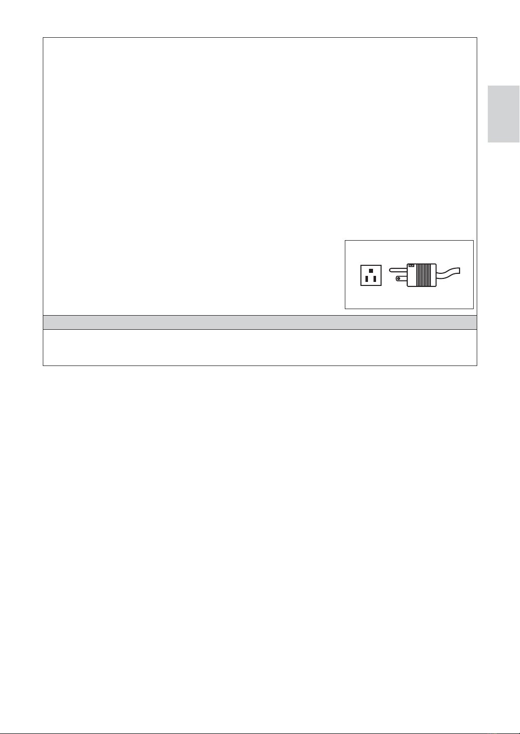
ŘTO PREVENT ELECTRIC SHOCK, use a main electrical outlet that is protective earthed.
ŘDo not use on the following patients.
-Those with medical complications or allergies
-Those who have pre existing conditions
(Eg Cardiac, Pulmonary, Renal disturbance or High blood pressure)
-Those who are pregnant or lactating
-Patients with cardiac pacemakers and infants
ŘBe careful not to get water or liquid disinfectant on the control unit. This could cause short circuits and lead to fire and/
or electric shock.
ŘRepeatedly turning the Main Power Switch ON and OFF may blow a fuse.
ŘWhen installing the product, provide space of approximately 10cm around the product for easy access to the inlet and
the Power Cord.
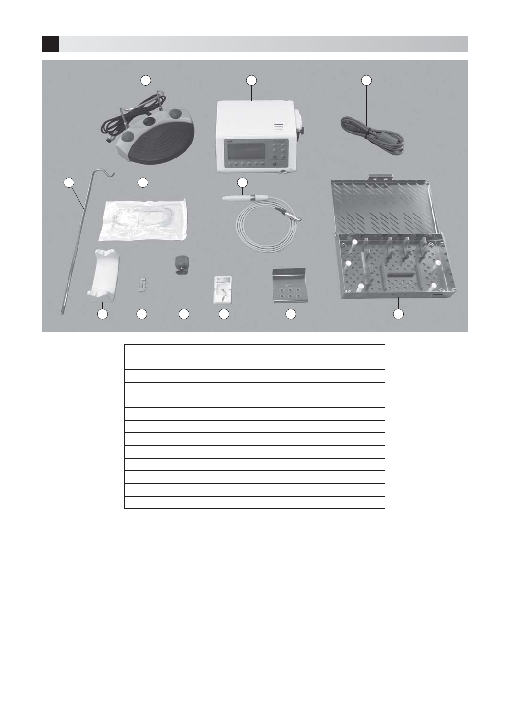
ŘThe Irrigation Tubes, included in the product package, are sterile. When using these products, follow the instructions
below.
- The irrigation tube is a single-use item. Do not reuse nor sterillize as product breakage or infection could occur.
- Check before use that the sterile package is NOT open nor damaged. Do not use products with open or damaged
packages as sterility will be negated and infection could occur.
- Observe the use-by date written on the sterile package label. Do not use expired products as sterility may be
negated.
ŘDo not point the handpiece LED light directly to the eyes of the patient, nor the operator, as it may be harmful to eyes.
CAUTION
ŘTo be confident in using this product, please read this Operation Manual before use. We suggest that to fully
understand the product functions and file for future reference.
ŘWhen operating the product always consider the safety of the patient.
ŘThe end user shall be responsible for any judgment that relates to the application of this product to a patient.
ŘThis product does not consider patient’s age (except infants), gender, weight or nationality.
ŘThis product does not consider operator’s age (mature person), height, weight, gender, or nationality.
ŘUsers are responsible for the operational control, maintenance and continual inspection of this product.
ŘThis device is for indoor use only.
ŘKeep the Control Unit on a level surface.
ŘDo not attempt to disassemble the product or tamper with the mechanism except as recommend by NSK in this
Operation Manual.
ŘDo not allow any impact on to the handpiece. Do not drop the handpiece.
ŘOperators and all others in the area must wear eye protection and a mask when operating this handpiece.
ŘShould the product function abnormally, cease operation immediately and contact your Authorized NSK Dealer.
ŘIf the Irrigation Pump gets wet, wipe it dry. If it remains wet, the roller in the pump may slip and the pump may not
operate properly.
ŘDo not bend or fold the Irrigation Tube while the Irrigation Pump is operating as the Tube may be damaged or may
detach.
ŘIf abnormality is detected in irrigation, it may be due to wear of the Irrigation Tube or leaking of saline from the Tube. In
such cases, replace the Irrigation Tube.
ŘDo not use high acid water or sterilizing solutions to wipe, immerse or clean the product.
ŘThe following products are delivered in a non-sterile condition and must be autoclaved prior to use. (Handpiece, Tip, Tip
Wrench, Tip Holder, Tube Holder)
ŘPerform regular function and maintenance checks.
ŘIf the product is not used for a long period check it is functioning correctly before using on a patient.
ŘTo avoid clinical downtime it is recommended that a spare be kept on hand in case of a breakdown during surgery.
ŘThis product may be affected by an electric scalpel. Turn OFF the Power Switch when an electric scalpel is used.
9DULR6XUJ(1LQGG

English
3
ŘThis product is rated Medical Electrical equipment. EMC (Electromagnetic compatibility) is described in the
documentation included.
ŘInstallation and use of this product requires special precautions regarding EMC according to the EMC information.
ŘPortable and mobile RF communications equipment can affect Medical Electrical equipment. Do not use RF equipment
near the product.
ŘThe use of ACCESSORIES such as handpieces and cables, other than those specified by the manufacturer, with
the exception of handpieces and cables sold by the manufacturer of this product as replacement parts for internal
components, may result in increased EMISSIONS or decreased IMMUNITY of this product.
ŘDo not place this product adjacent to, or on top of, another device. This product and NSK Surgic Pro can however be
stacked for use with the NSK Link connection.
ŘThe system may present a possibility of malfunction when used in the presence of an electromagnetic interference
wave. Do not install the system in the vicinity of any device which emits magnetic waves. Turn OFF the Main Power
Switch of the system an ultrasonic oscillation device or an electrode knife is located close to the vicinity of use.
ŘThe handpiece may get hot when some types of tips are used at high power level or in an overloaded state. (The
temperature of the handpiece surface might exceed 41˚C.) If such abnormality is found, stop using for about 5 minutes
to allow the handpiece to cool.
ŘFor added safety install the Control Unit in a place where the AC POWER Cord
can be easily removed. (It is possible to disconnect the control unit from the
power source by removing the AC POWER Cord.)
ŘGrounding reliability can only be achieved when the equipment is connected to
an equipment receptacle marked "Hospital Only" or "Hospital Grade".
ŘU.S. Federal law restricts this device to sale by or on the order of a licensed
physician.
NOTICE
ŘNo special training is required for this device.
ŘThe handpiece or handpiece cord during operation could interfere with computers, LAN cables in close vicinity, or
could cause noise in radio receivers nearby.
*Emission: Unnecessary energy generated by the device.
*Immunity: Tolerance to unnecessary energy received by the device.
Power plug below is used in North America area.
Plug Type NEMA 5-15P (Hospital Grade Type)
9DULR6XUJ(1LQGG

4
3Package Contents
No. Part Name Quantity
1 Foot Control 1
2 Control Unit 1
3 AC Power Cord 1
4 LED handpiece with cord (Unshielded 2m) 1
5 Irrigation Tube 5
6 Irrigation Pole 1
7 Handpiece stand 1
8 Tube Holder 7
9 Tip Wrench 1
10 Tip 6
11 Tip Holder 1
12 Sterilization Cassette 1
1 2 3
45
7 8 9
10 11 12
6
9DULR6XUJ(1LQGG

English
5
4Component Names
4-1 Control Unit
(11) POWER key
(10) PROGRAM key
(9) MEMORY key
(8) AUTO CLEANING
key
MODE key
(7) SELECT key
(1) LIGHT key
(2) COOLANT
key
(3) P key
(PERIO Mode)
(4) E key
(ENDO Mode)
(5) S key
(SURG Mode)
(6) BURST key
4-1-1 Keys on the Operation Panel
(1) LIGHT key
To select the Handpiece illumination intensity: OFF / LOW / HIGH
(Default setting : HIGH)
(2) COOLANT key
To select the Coolant Flow from 5 levels.
(3) P key
To set the PERIO Mode (the mode suitable for maintenance, etc.).
(4) E key
To set the ENDO Mode (the mode suitable for the root canal treatment).
(5) S key
To set the SURG Mode (the mode suitable for cutting bones).
Handpiece Cord Connector Socket
Foot Control Cord
Connector Socket
Fuse Box
Main Power
Switch
Front Panel
LCD Display Irrigation Pump Coolant Solution
Hanger Post Holder
AC Power Cord
Connector Socket
SG Link Cable Socket
Operation Panel
9DULR6XUJ(1LQGG

6
(6) BURST key
To set the Burst Output Level (only for the SURG Mode)
Each time the key is pressed, the setting changes as follows: OFF B1 B2 B3 OFF.
*Burst function: Increases and decreases vibration at regular intervals. Select an appropriate setting according
to the hardness of the patients’ bones (bone density).
*Frequencies for Burst are B1: 10Hz, B2: 30Hz and B3: 60Hz.
(7) SELECT key
This key is used when two systems (NSK VarioSurg 3 and NSK Surgic Pro) are operated by a single Foot
Control.
*Surgic Pro (sold separately) and the Link Set (sold separately) are required in order to use this key.
(8) AUTO CLEANING key
For cleaning the irrigation circuit in the Handpiece and tube.
(9) MEMORY key
To set the program memory for the values which are displayed in the Panel.
(10) PROGRAM key (- +)
For calling up the set values memorized in the program.
(11) POWER key (- +)
For setting the Power Level.
By pressing (+) and (-) keys, the set value increases and decreases respectively.
*When the key is held down, the value increases or decreases continuously. However, when (+) key is held
down, the value stops at 100% for the sake of safety. If you want to further increase the value, press the key
again.
Program No. Mode Burst function*1Power range Coolant flow
(5 levels) Lighting brightness
1
SURG
Available
(Off, B1: 10Hz,
B2: 30Hz,
B3: 60Hz)
10 – 150%
In multiples of 10% 17 - 95 ml/min*2
OFF/LOW/HIGH
2
3
4
5
6ENDO
Not available
5 – 100%
Below 50%, multiples of 5%.
50% and larger, multiples of 10%.
3 - 55 ml/min*2
7
8PERIO
9
*1 Burst function: Vibration levels can be changed at certain intervals. Levels can be selected depending on patient’s
bone hardness (density).
*2 The amount of water flow may vary slightly depending on the condition of the Irrigation Tube.
Ř While the Handpiece is vibrating, the following keys cannot be operated.
(3) P key (4) E key
(5) S key (7) SELECT key
(8) AUTO CLEANING key (9) MEMORY key
(10) PROGRAM key (- +)
NOTICE ŘProgram numbers are allocated to each Mode as shown in the following table. Each program number can
be set only for the allocated Mode.
9DULR6XUJ(1LQGG

English
7
4-1-2 LCD Display on the Operation Panel
(A) Surgic Pro Display
This is displayed only when the this VarioSurg 3 is connected to NSK Surgic Pro via the NSK Link Set and
Surgic Pro has been selected by SELECT key.
*For the Link function, refer to “8-3 Link function with Surgic Pro”.
(B) POWER Display
Displays when vibration is active from the Handpiece.
(C) POWER Level Display
Displays the set Power Level (5 – 150%).
(D) Program Number
Displays the selected program number.
(E) POWER Bar Graph
The relevant POWER level is indicated by the number of indicator bars illuminated.
Each lower horizontal bar represents 50 %.
Each upper vertical bar represents 10%. The maximum number of bars is 15.
In Auto Cleaning mode, the countdown of the remaining time is displayed.
(F) Brightness
Displays the selected illumination intensity.
(G) Coolant Flow Level
The selected Coolant Flow is displayed on a scale of 1 - 5 (1 is the least flow).
(H) Mode
Displays the selected Mode.
(I) Burst Output Level
Displays the Burst Output setting. Displays only in SURG Mode.
NOTICE ŘWhen the transparent protective sheet on the Operation Panel is peeled off or when an object charged
with static electricity is placed near the LCD Display, fine lines may appear in the display area. This is
normal and the lines will disappear after a short time.
(D) Program
Number
(E) POWER
Bar Graph
(F) Brightness (G) Coolant Flow Level (I) Burst Output Level
(A) Surgic Pro Display (B) POWER Display (C) POWER Level Display
(H) Mode
9DULR6XUJ(1LQGG

8
(a) Ultrasonic ON-OFF Button
To activate Tip Piezo vibration depress this control.
(b) Coolant Flow Level Selection Button
The Coolant Flow can be selected from 5 levels. Each time the button is depressed the flow will increase by 1
level. If the button is depressed when the Flow is in the level 5 it returns to level 1. (Level 0 cannot be selected
for the Coolant Flow.)
(c) Program Selection Button
A specific Program Number can be selected.
Each time the button is depressed the Program Number increases by one. When the button is held down for
approximately 1 second the program returns to the previous number.
(d) Burst Output Mode Selection Button
Burst Output Mode setting can be selected.
(d) Burst Output Mode
Selection Button
Foot Control Cord Plug
(a) Ultrasonic ON-OFF button
(b) Coolant Flow Level
Selection Button
(c) Program Selection Button
5Installation
5-1 Connection of the LED handpiece & cord
1) Position the Handpiece Cord so that the mark is facing up and is
aligned with the mark on the Control Unit. Firmly push the Cord
Coupling into the Handpiece Cord Socket until it clicks.
2) Confirm that the Cord Coupling is properly locked in position by
pulling it gently.
To disconnect the Coupling pull back the Lock Joint then pull back
further to disconnect the cord.
Fig. 1
4-2 Foot Control
Lock Joint
Mark
9DULR6XUJ(1LQGG

English
9
5-2 Connection of the Foot Control
1) Turn the Foot Control Cord Plug so that the screw faces down. Insert
the Plug so that it correctly fits into the Foot Control Connector
Socket of the Control Unit.
2) Secure the lock nut of the Foot Control Cord Plug.
5-3 Connection of the AC power cord
1) Turn the Power Switch OFF. ( side)
2) Insert the AC Power Cord so that it correctly fits into the AC Power
Cord Connector Socket at the back of the Control Unit.
3) Plug the AC power cord into a wall outlet specified for medical use.
5-4 Connection of the Irrigation Tube
1) Turn the Pump Cover lever for the Irrigation Pump, located
at the side of the Control Unit, clockwise by 180 degrees to
open the Pump Cover.
2) After checking the irrigation direction, insert the tube into
the Irrigation Pump.
3) Align the Tube Clamps of the Irrigation Tube with the tube
guides and set the Tube.
4) Turn the Pump Cover Lever anticlockwise by 180 degrees
to close the Pump Cover.
Fig. 2
Fig. 3
Fig. 4
Fig. 6
Fig. 5
Lock Nut
Foot Control Cord Plug
The screw should face down.
AC power cord
Pump cover lever
CAUTION
ŘDo not tug the AC power cord by holding and pulling its cord.
ŘMake sure that the device has completely stopped before removing or inserting the AC power cord.
Tube guide
Align
Align
Direction of Irrigation
Tube Clamp
Pump cover
<When the pump cover is open>
<When the pump cover is closed>
9DULR6XUJ(1LQGG

10
5-5 Connection of the Coolant Solution Hanger Post
Align the Coolant Solution Hanger Post onto the Control Unit
holder and firmly push it down.
5-6 Insertion of the Irrigation Tube
1) Close the Tube Clamp which is placed between the Irrigation Needle and the Irrigation
Pump. (Fig. 9)
2) Hang the Solution Pack onto the Coolant Solution Hanger Post.
3) Insert the Irrigation Needle into the Pack entry point. (Fig. 10)
4) Insert the other Irrigation Tube tip into the handpiece Irrigation Nozzle. (Fig. 11)
5) Open the cap to let air into the Pack. (Fig. 12)
6) Open the Tube Clamp.
CAUTION
ŘBefore closing the Pump Cover, make
that the tube is correctly positioned on
the rollers. If the tube is not correctly
positioned, and the Cover is closed, the
tube could be crimped or sheared.
ŘBefore fitting the Irrigation Tube, make sure
the Irrigation Pump is stopped.
Fig. 8
Fig. 7
Fig. 9
Fig. 10 Fig. 11 Fig. 12
CAUTION
ŘInsert the Coolant Solution Hanger Post all the way down firmly. If the Post guide and the groove guide are
not aligned, the Post cannot be inserted all the way down.
ŘUse a 500ml pack of solution. Maximum pack size is 800g for the Coolant Solution Hanger Post.
Tube Clamp
Mouth of the
pack
Irrigation Needle
Irrigation Nozzle
Cap
Align
9DULR6XUJ(1LQGG

English
11
5-7 Connection of the Tube Holder
Push the Tube Holder on to the Handpiece Cord, then push the
Irrigation Tube into the Tube Holder.
CAUTION
CAUTION
ŘAlways use a Pack with a sufficient quantity of saline.
ŘBefore opening the Tube Clamp, always close the Pump Cover. If the Tube Clamp is opened while the
Pump Cover is open, saline will flow out of the Irrigation Tube Tip.
ŘWhen the coolant solution runs short, stop using the system and replace the Coolant Solution Pack.
ŘBe sure to check that the coolant solution is flowing properly before using the system again.
ŘBundle the Handpiece Cord and the Irrigation Tube at a
total of 7 locations.
Fig. 14
Fig. 13
Irrigation Tube
Tube Holder
Handpiece Cord
9DULR6XUJ(1LQGG

12
5-8 Mounting the Tip
1) First, lightly screw in the Tip with by hand. (Fig. 15)
2) Match the square shape of the Tip with the hole of the Tip Wrench, then insert the Tip into the hole. (Fig. 16)
3) Rotate the wrench in the (clockwise) direction, (Fig. 17 and 18) until it makes a click sound and cannot rotate any
further.
* To remove the Tip, rotate the wrench in the (counter-clockwise) direction shown in Fig. 17 and Fig. 18.
Fig. 16Fig. 15
Fig. 18Fig. 17
TightenLoosen
Tighten
Loosen
CAUTION
ŘWhen attaching or removing a Tip, which is longer than the Tip Wrench, be careful that the protruding Tip
does not cause an injury.
ŘDo not use a Tip which has been damaged, bent or corroded as it will be weakened and may break while
in use.
ŘTo avoid bending of the Tip thread or disengaging of the Tip, always make certain that the Tip is inserted
at the correct angle and firmly tightened.
ŘIf debris is found on the Tip thread clean the Tip immediately so as to avoid possible weak vibration
ŘDo not attempt to sharpen or bend the Tip as this may cause the Tip to break during operation, or the
vibration may be weakened.
ŘWhen Tip become worn vibration may weaken or the Tip may suddenly break. If a weak Tip is detected
replace with a new one.
ŘTips need to correctly inserted and tightened using the Tip Wrench. If the Tip is not tightened sufficiently
vibration may be weak.
ŘWhen inserting a Tip always wear surgical gloves and ensure the Tip, Handpiece and Tip Wrench are in an
hygienic condition.
ŘBefore connecting or disconnecting the Handpiece Cord or Irrigation Tube make sure to remove the Tip
first to avoid injury by the Tip.
ŘTip Wrench will wear with frequent use time and may need annual replacement.
ŘUse only genuine NSK Tips. Other brand Tips may cause malfunction, damage or injury:
- Poor vibration when an incompatible thread has been forcibly fitted.
- The patient may swallow pieces of broken non genuine Tips.
- Damage or premature wear of the Handpiece thread.
9DULR6XUJ(1LQGG

English
13
5-9 Handpiece Stand
When the Handpiece is not in use, place the Handpiece horizontally on the Handpiece stand.
CAUTION
ŘMake sure that the Tip does not rest on the Handpiece Stand.
ŘMake sure that the Handpiece rests horizontally on the Handpiece stand, and not at an angle.
ŘTo maintain an hygienic condition, the Handpiece Stand should frequently be cleaned with alcohol.
6Check before treatment
Before use, operate the product without patient contact and check the following points. If any abnormality, such as low
vibration, noise, heat, is detected at anytime disconnect the product and contact your Authorized NSK Dealer.
-Is irrigation solution flowing correctly at the Tip?
-Is the Tip vibrating correctly?
-Are there any abnormalities at the Tip, Eg. vibration, noise and heat?
-Is the Handpiece illumination operating correctly?
7Operating method
7-1 Check Irrigation
1) Confirm that the Irrigation Tube correctly connected to the Coolant Solution Pack, the Irrigation Pump and the
Handpiece.
2) Turn ON (-side) the Power Switch.
3) Open the Tube Clamp which is placed between the Irrigation Needle and the Irrigation Pump. Then, depress the
Ultrasonic ON/OFF Button on the Foot Control and confirm that the irrigation solution correctly flows from the Tip.
When a new Irrigation Tube is used, it may take several seconds before irrigation solution flow commences.
7-2 Set the Power Level
1) Change the Mode – Use MODE key.
2) Select the Program No. – Use PROGRAM key.
3) Adjust the Power Level – Use POWER key.
4) Adjust the Coolant Flow Level – Use COOLANT key.
5) Adjust the Handpiece illumination intensity
– Use LIGHT key.
6) Select the Burst Output Level – Use BURST
key. (In SURG Mode only).
* Power outputs at various Modes are
compared in Fig. 20.
No Tip contact
Horizontal Not horizontal
Fig. 19
SURG
OUTPUT
ENDO
PERIO
10%
5% 00%
100%
5% 100%
150%
Fig. 20
9DULR6XUJ(1LQGG

14
7-3 Activation
The Tip will commence vibrating when the ON-OFF Foot Control button is depressed.
CAUTION
ŘUse the Tip ONLY in the Mode, and within the Power Range, as
displayed on the Tip case label. If used outside the prescribed
power range the Tip may break, and the tooth surface or soft
tissue may be damaged. (Fig. 21)
ŘONLY tips specified for maintaining prostheses can be applied
to prostheses. Contact of other types of tips with prostheses
may cause Tip breakage.
CAUTION
ŘStart with a low power setting within the power range, observing the patient’s reaction and according to
the treatment plan.
ŘAlways use the irrigation. If the irrigation is not sufficient, the Handpiece may excessively heat, or oral
injury may occur.
ŘDo not apply excessive pressure to the Tip.
ŘDo not place the active Tip anywhere other than the specific treatment area, as the ultrasonic vibration
may cause oral injury.
ŘEven if the power level is correctly set for the Tip in use application of excessive pressure to the Tip may
cause Tip damage. Should Tip breakage occur, immediately evacuate the oral cavity of any Tip pieces
using strong suction.
ŘIf Tip vibration reduces during operation, release the Foot Control activation button, and then again
depress the Foot Control activation button. If the vibration level still does not return to normal check that
the Tip is correctly and firmly positioned. Incorrectly inserted Tips may loosen during operation and power
loss may be experienced.
ŘDo not connect or disconnect the AC power or the Handpiece Cord while Foot Control is depressed.
8Various functions
8-1 Memory function
The set values displayed in the panel (Eg. Mode, Program No., Power Level, Irrigation Flow Level, illumination intensity)
can be memorized in each program. Once memorized, the programs can be called up whenever required.
1) Press the PROGRAM key and select the Program No. for memory.
2) Check the values of the parameters to be stored.
3) Hold down the MEMORY key for approximately one second. When the notification tone beeps, memorizing the
setting is complete.
8-2 Volume selection function for the notification tone
Sound volume of the notification tone can be selected between high & low.
1) Make sure the power is off. Then turn ON the power while holding down the BURST key.
2) The notification tone in the selected volume sounds.
3) To change the sound volume, repeat 1) and 2) above.
8-3 Link function with Surgic Pro
This product has a link function whereby two systems (NSK VarioSurg 3 and NSK Surgic Pro) can be operated via one
Foot Control.
* To use this function, Surgic Pro (sold separately) and the SG Link Set (sold separately) are required. For the Link
function, refer to the Operation Manual included with the SG Link Set.
SG5
Z305106
POWER RANGE
S
Power rangeMode
Fig. 21
9DULR6XUJ(1LQGG

English
15
9Maintenance
After each patient maintain the product as follows.
9-1 Auto Cleaning
1) Remove the Irrigation Needle from the solution pack.
2) Place the Irrigation Needle in distilled or deionized water in an open container.
3) Place the Tip of the Handpiece into the water.
4) Start Auto-Cleaning by holding down the AUTO CLEANING key for
approximately one second.
While Auto-Cleaning is active “CLn” appears in the POWER Display
on the LCD Display. The Bar Graph indicates the time remaining (Auto
Cleaning lasts for approximately 30 seconds).
*Auto Cleaning can be stopped anytime by pressing AUTO
CLEANING key.
5) Once Auto Cleaning has completed, the LCD Display returns to
normal display.
8-4 Factory Settings
When initialized, the device will revert to factory settings. Preferred settings and programs, etc. will be erased, so be
sure to make memos of them.
1) Turn power on while pressing the PROGRAM (+ -) key.
2) “SEt” will come up on the LCD Display. (there will also be a short beep) By pressing BURST key, the device will
revert to factory settings.
3) “FIn” will come up on the LCD Display. (there will also be a long beep) Initializing is complete when the screen
goes back to its usual display.
9-2 Cleaning the LED handpiece with cord
1) Detach the Handpiece Cord from the Control Unit.
2) Remove the Irrigation Tube from the Handpiece and dispose.
3) Remove any debris from the product. Do not use a wire brush.
4) Wipe clean with alcohol.
This icon denotes that the product can be washed via Thermo Disinfector.
At the print date of this Operators Manual, the Miele (Model:G7882) is the only Thermo-Disinfector verified for use with
the VarioSurg 3.
Refer to the Thermo-Disinfector manual.
CAUTION
ŘPerform Auto Cleaning after every use. If Auto Cleaning is omitted, the Handpiece may clog or malfunction.
CAUTION
ŘWhen using in a Thermo-Disinfector, ensure that the Handpiece and Handpiece Cord are stable by placing
them in a basket or container.
ŘNever use solvents, such as benzene and thinner for cleaning.
Fig. 22
9DULR6XUJ(1LQGG

16
9-4 Cleaning the Control Unit and the Foot Control
1) Turn OFF the power and disconnect the AC power cord from the wall power socket.
2) Wipe the surface, first with a moist cloth, then with an alcohol soaked cloth.
9-5 Cleaning other components
Remove surface debris with a bristle brush (NOT METAL BRISTLES) then wipe the surface with an alcohol soaked cloth.
9-6 Sterilization
Autoclave sterilization is recommended.
Autoclave sterilization is required for before the first use and then after each patient as noted below.
The following items can be autoclaved.
LED Handpiece with cord, Tip, Tip Wrench, Tip Holder, Handpiece Stand, Tube Holder, Sterilization Cassette.
1) Place the Handpiece and Tip Wrench in the Sterilization cassette. (Fig. 24)
2) Place the Tips onto the Tips Holder before putting the Tips Holder in the Sterilization Cassette.
3) Commence Autoclave sterilization. Autoclavable under the conditions below.
Autoclave for more than 20 min. at 121°C, or 15 min. at 132°C, or 3 min. at 134°C.
4) To maintain sterility, keep the product sealed in the autoclave pouch until required for use.
CAUTION
ŘDo not place Maintenance Tips in the Tip Holder, as these Tips are too long. Use an autoclave pouch when
sterilizing Maintenance Tips.
ŘDo not autoclave the product with other instruments even when it is in a cassette. This is to prevent
possible discoloration and damage to the product from chemical residue from other instruments.
ŘKeep the product in suitable atmospheric pressure, temperature, humidity, ventilation, and sunlight. The
9-3 Cleaning the Glass Rod
Wipe clean the Glass Rod tip with an alcohol immersed cotton swab.
Remove all debris. (Fig. 23)
Tip holder alternative
location.
Tip Holder
Tube Holder
Tip Replacement
Wrench (for V10-S)
(Option)
Tip Wrench
Sterilization Cassette locations for VarioSurg 3 components
LED Handpiece with cord
Fig. 24
Fig. 23
Cotton swab
Fiber end face
CAUTION
ŘDo not use needles or blades when cleaning the
Glass Rod as the glass surface may be scratched and
illumination intensity will be reduced.
9DULR6XUJ(1LQGG

English
17
10 Periodical Maintenance Checks
Perform periodical maintenance checks every three months, referring to the check sheet below. If any abnormalities are
found, contact your Authorized NSK Dealer.
Points to check Details
Vibration Operate the Handpiece and confirm that there are no vibration, noise, or heat abnormalities
Irrigation Confirm that there are no abnormalities in the Coolant Flow Level or no leaks
Illumination Confirm that the Handpiece LED illumination is correctly functioning
Display Immediately after AC power is switched ON, all display lights should illuminate. Confirm that
all display lights are working
Foot Control Confirm that all the buttons operate normally
11 Error code
If the device stops operating due to excessive pressure, Tip or cord disconnection or incorrect usage, the LCD Display
will show an error code. If this happens, release, then depress the Foot Control to repeat the error check. If the problem
self corrects the error display will cancel and operation can be resumed. If the error display is repeated refer to the table
below and take appropriate action.
Error code Description of error Cause of error Check / Remedy
E2 Vibrator error
The end of the Tip is under too
much pressure.
Avoid applying excessive pressure. If the Tip
is caught during a cutting operation, press the
Ultrasonic ON-OFF Button and gently extract the
Tip while vibrating it. (Never use force)
The Tip is not correctly
inserted. The Tip is not
tightened sufficiently.
Insert the Tip and tighten it using the Tip Wrench
until it clicks into position.
The Handpiece Cord is not
properly connected.
Breaking in the Handpiece
Cord.
Check the connection of the Handpiece Cord.
If the problem persists, contact your Authorized
NSK Dealer.
E4 Overheating inside the
Control Unit
Increase in temperature
inside the Control Unit due
to prolonged use under high
pressure.
Turn OFF the power, allow time to cool, then
operate the device again.
If this error code is displayed frequently, contact
your Authorized NSK Dealer.
E8 Pump error
The Irrigation Tube is caught
in the Pump Roller.
Failure of the Pump.
Check the Irrigation Tube is correctly connected
If the problem persists, contact your Authorized
NSK Dealer.
CAUTION
air should be free from fine dust, salt and sulphur.
ŘDo not heat or cool the product too quickly. Rapid temperature change could cause damage to the
product.
ŘIf the sterilizer chamber temperature exceeds 135°C during the dry cycle then delete the dry cycle.
ŘAutoclave sterilization is recommended for the product. The validity of other sterilization methods is not
confirmed.
ŘDo not touch the product immediately after autoclaving as it will be very hot and it must remain in a sterile
condition until used.
ŘAfter autoclave sterilizarion if there are water drops on the LED Handpiece with Cord, wipe them away, as
they may cause discolouration.
NOTICE ŘNSK recommends Class B Sterilizers as stated in EN13060.
9DULR6XUJ(1LQGG

18
12 Troubleshooting
If a problem is detected, check the following list before requesting service. If none of the listed remedies corrects the fault
contact your Authorized NSK Dealer.
Trouble Cause Remedy
Control Unit cannot be turned
ON (LCD display does not turn
on)
AC Power Cord is not connected to Control
Unit.
Check the connection.
AC Power Cord is not plugged into wall
outlet.
Check the connection.
Fuse has blown. Service only by Authorized NSK Dealer.*
Control Unit turns ON,
Ultrasonic Output is displayed,
and beep sound is heard.
Foot Control is being operated. To prevent accidents, the Handpiece will
not work if the Main Power is turned ON
while the Foot Control is being operated.
Activate the Foot Control again.
The Tip does not vibrate (no
indication of Ultrasonic Output
Display).
Foot Control is not connected. Check the connection.
Handpiece Cord is not connected to Control
Unit.
Check the connection.
The Tip does not vibrate
(Indication of Ultrasonic Output
Display).
Faulty circuit. Service only by Authorized NSK Dealer.*
Weak vibration The Tip is worn or broken. Replace with a new Tip.
Wrong mode. Change to the correct mode.
The Tip is not correctly tightened. Tighten the Tip until the Tip Wrench clicks.
Incorrect power setting. Change to the correct mode and power
range for the Tip as indicated on the Tip
case.
Foot Control not connected properly. Connect Foot Control properly.
Failure inside the Handpiece. Service only by Authorized NSK Dealer.*
Failure inside the Foot Control. Service only by Authorized NSK Dealer.*
The Tip breaks easily. Power Level is not right for the Tip
mounted.
Change to the correct mode and power
level indicated on the selected Tip case.
The Tip comes off. The Tip is not correctly tightened. Tighten the Tip until the Tip Wrench clicks.
Handpiece makes a loud
noise.
Power Level is not correct for the selected
Tip.
Change to the mode and power level
indicated on the selected Tip case.
Tip is not correctly tightened. Tighten the Tip until the Tip Wrench clicks.
Failure inside the Handpiece or the Control
Unit.
Service only by Authorized NSK Dealer.*
Handpiece becomes hot. Power Level is not right for the selected
Tip.
Change to the mode and power level
indicated on the selected Tip case.
Tip is not tightened sufficiently. Tighten the Tip until the Tip Wrench clicks.
Failure inside the Handpiece or the Control
Unit.
Service only by Authorized NSK Dealer.*
Debris is clogging the Handpiece and
blocking irrigation flow.
Place air syringe against Water Pipe and
blow air through it. If this does not clear it,
Contact your Authorized NSK Dealer.
Irrigation is not supplied. Make sure the pack contains solution
and the Irrigation Tube is not leaking nor
blocked.
Irrigation does not exit as
spray.
Spray depends on the combination of flow
level, power level, and Tip shape.
With some flow levels and Tip shapes, it is
more difficult to form a spray. This is not a
malfunction.
9DULR6XUJ(1LQGG

English
19
Water does not exit, or flow
level is low.
Foot Control is not connected. Check the connection.
Irrigation Tube is not connected to Irrigation
pack or Handpiece.
Check the connection.
Irrigation Tube is not properly mounted to
the pump.
Check the connection.
The Pump Cover is open. Close the cover.
The Irrigation Tube is broken (leaking). Replace the Irrigation Tube.
Irrigation leak. Leak from the connection between
Irrigation pack and Irrigation Tube.
Insert Irrigation Tube Needle all the way
into the Irrigation pack.
Leak from the connection between
Handpiece and Irrigation Tube.
Insert the end of the Irrigation Tube
completely into the Handpiece water pipe.
Leak from Irrigation Tube. Replace the Irrigation Tube.
Irrigation does not stop. Mode is set to Auto Cleaning. To stop irrigation, press the Flow key.
Faulty circuit. Service only by Authorized NSK Dealer.*
Handpiece LED does not
illuminate.
LED is burned out. Service only by Authorized NSK Dealer.*
Failure inside the Control Unit or inside the
Handpiece Cord.
Service only by Authorized NSK Dealer.*
Failure or disconnection of the circuit. Service only by Authorized NSK Dealer.*
LCD display does not properly
display.
Part of display is missing.
Overheating. Heat can cause LCD display malfunction.
Turn the Main Power OFF to cool down.
Error Code is displayed. Refer to the Error Code table.
Failure of the LCD display or driving circuit. Turn the Main Power OFF and then ON. If
part of initial display is still missing
Contact your Authorized NSK Dealer.
Settings are not memorized
Wrong settings are
memorized.
Figures have been temporarily changed. Increase or decrease the Program No. by
one, and then return to the original setting.
Foot control is being operated. Settings cannot be saved while LED
Handpiece with cord is operating.
An Error Code is displayed. Refer to the Error Code table.
* Repairs cannot be made by the customer.
9DULR6XUJ(1LQGG
Table of contents
Languages:
Other NSK Medical Equipment manuals

NSK
NSK Varios Combi Pro User manual

NSK
NSK Osseo 100 User manual

NSK
NSK Primado2 User manual

NSK
NSK M40 XS User manual

NSK
NSK Surgic Pro+ Installation manual

NSK
NSK Primado2 User manual

NSK
NSK Ti-Max X450L User manual

NSK
NSK SGS Series User manual

NSK
NSK Varios 560 LUX User manual

NSK
NSK Link Stand2 User manual
Popular Medical Equipment manuals by other brands

EDAN
EDAN SE-1201 user manual

ADL
ADL soft air simplex wds user manual

Planmeca
Planmeca ProMax 3D Plus manual

Edwards Lifesciences
Edwards Lifesciences 3000TFX PERIMOUNT Magna Aortic Instructions for use

GCE druva
GCE druva MEDIUNIT Instructions for use

PFM Medical
PFM Medical pfm Stretching Table 1100 operating manual