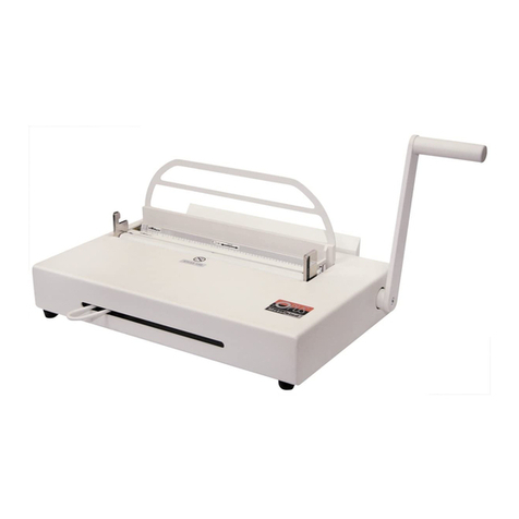
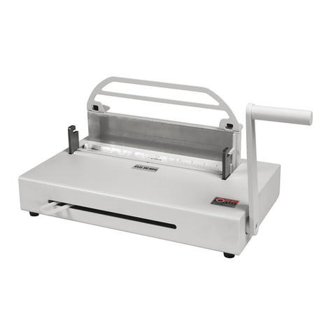
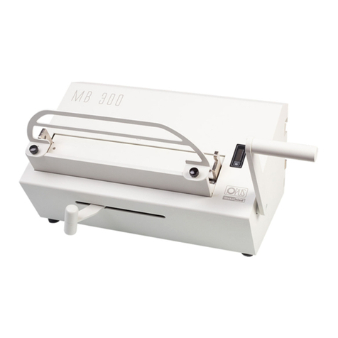
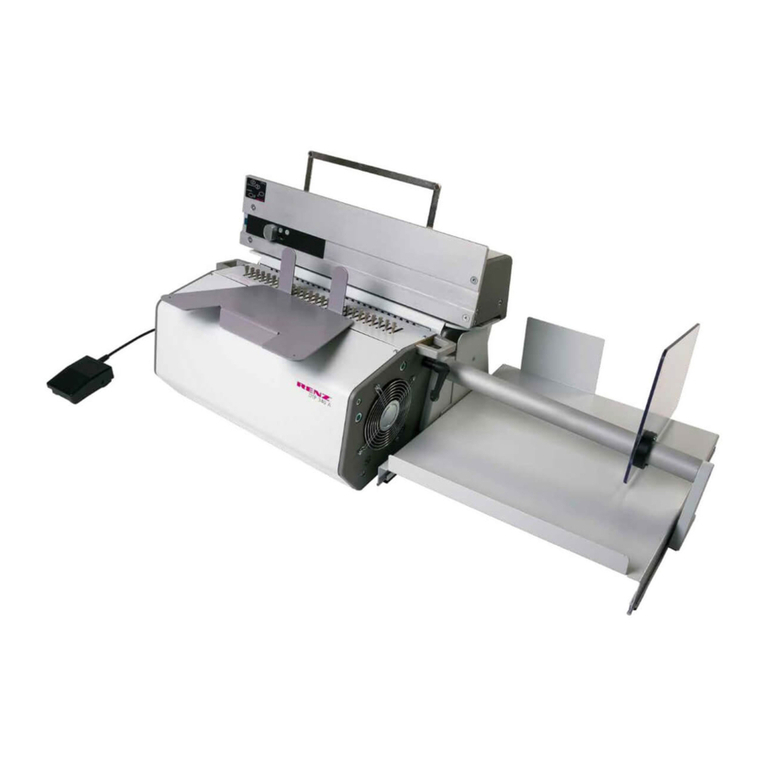
Opus Atlas 300 mono User manual

1
User’s guide
Atlas 300 mono
GB
Atlas 300 mono • User’s guide GB

2
CONTENTS:
METALBIND SYSTEM
ATLAS MONO DESCRIPTION
IMPORTANT SAFEGUARDS
PREPARATION TO WORK
IMAGE PRESS DEVICE
IMAGE PRESS DEVICE SAFETY INSTRUCTIONS
PREPARATION TO WORK
PREPARING T E FONTS
PREPARING T E MATRIX
OT STAMPING ON COVERS
1METALBIND SYSTEM
Atlas 300 mono binding machine was designed to bind documentation with
channels and covers of Metalbind system (available from OPUS). After assembling
the Image Press device it is possible also to make hot stamp on covers.
Metalbind
1
2
3
4
5
6
6 - special protrusions help
to centre the document
within the channel and
to protect it against
movements along
the channel
This is the strongest binding method
because covers and pages are kept from the outside by a channel
1 - the back wall of the channel is bent to keep covers and pages
2 - the channels are covered with embossed material
3 - the special shape of the channel for perfect look of the document
4 - pages are not harmed by the channel
5 - the front wall is never deformed
5 BINDING METALBIND
6 DE-BINDING METALBIND
7 C-BIND SYSTEM
OT STAMPING ON O.C ANNEL BINDING C ANNELS
OT STAMPING ON CD/DVD CDCOVERS
TEC NICAL DATA
DECLARATION OF CONFORMITY

3
Atlas 300 mono • User’s guide GB
2DESCRIPTION - Atlas 300 mono
1 - handle
2 - adjusting lever
3 - binding slot
4 - hooks
5 - de-binding wedge
6 - channel width selecting tool
7 - magnetic guiding bar
8 - guide & bind bar (thin)
9 - guide & bind bar (thick)
10 - side stop
11 - adjustable side stop
12 - extended back support
1
2
6
7
9
8
510
3
8/9 7
3
411 12
11

4
IMPORTANT SAFEGUARDS
• Before operating the equipment read the ealth & Safety precautions, manufacturers recommenda-
tions and the operation/user manual
• The operation/user manual should be easily available at any time for the operator
• The equipment must be kept away and out of reach of children
• Equipment must be protected against dust and damp and should be positioned on a strong and sturdy
flat surface
• While binding, do not put fingers into the binding slot
• Be careful when moving the equipment it is very heavy
• Pay attention the de-binding wedge has sharp edges
• The machine must not be used for any other purposes other than those indicated in the operat-
ing/user manual
• It is necessary to check and supervise if the equipment is being used and operated correctly, before
reporting any malfunctions or problems to the service department or dealer
• Equipment must not be located outside or operated in temperatures under 8˚C/46.4˚F and must be ope-
rated in accordance with the general ealth & Safety rules failure to do so could cancel the guarantee
• Repairs must be carried out by authorized sta, during the guarantee period, failure to do so could
cancel the guarantee
PREPARATION TO WOR
Unpack the machine and install the extended back support (15) on the housing (the adequate holes are
drilled in the housing and screwed bolts). Screw the handle (1) to the machine using the allen key at-
tached. In the shelves at the bottom of the machine there are two guide&bind bars and de-binding wedge.
Three bars are included to the machine: magnetic guiding bar (7) - with magnet, allows to insert the
documentation into the channel easily, guide&bind bar (8) thin - with a ruler, to be used with 20-32
size channels, helps to insert the document into the channel, guide&bind bar (9) thick - with a ruler,
to be used with 5-16 size channels, allows to place the document into the channel and reduces the
size of the binding slot. The shape of bars is specially designed to make inserting the documentation in
the channel as easy as possible.
Put the magnetic guiding bar (7) on the movable binding jaw and insert the guide&bind bar (8/9) by
the back wall of the binding slot (3). The cut side of each bar should be directed to the inside of the
binding slot (3). The machine is ready to work.
BINDING METALBIND
Important! If you are going to use Atlas 300 mono to bind and hot stamp on the same cover, re-
member to hot stamp an inscription first and then bind the document. Therefore, in such case, be-
fore binding refer to the user`s guide of Image Press device (on the following pages of this manual)
to make the hot stamping.
1. Use the channel width selecting tool (6) to choose the proper channel size. The channel sizes and corre-
sponding number of pages you can bind with them are shown in the table.
/p/ – hard cover/pile of pages/ hard cover S/p/S – soft cover/pile of pages/soft cover
/p/T – hard cover/pile of pages/transparent cover O/p/O – pile of pages bound only with a channel
Channel size H/p/H H/p/T S/p/S O/p/O
5 10-31 10-33 10-34 10-38
7 32-60 34-63 35-63 39 - 67
10 61-89 64-92 64 - 92 68 - 97
13 90-118 93-121 93 - 121 98 - 126
16 119-148 122 - 150 122 -150 127 - 155
20 149 – 186 151 – 189 151 – 189 156 – 194
24 187 – 225 190 – 228 190 – 228 195 – 233
28 226 – 264 229 – 266 229 – 267 234 – 271
32 265 – 303 267 – 305 268 – 308 272 – 310
4
5
3

5
Atlas 300 mono • User’s guide GB
Important! The thickness of the
documentation to be bound must
be at least 1,8 mm (with the
cover). If the documentation is
thinner, it is necessary to use the
filling strips (e.g. O.Filling Sticky
available from OPUS) to make it
thick enough.
2. Make sure the binding bars are correctly inserted into the binding slot (3)
Important!
• for 5-16 mm channels - insert a thick guide&bind bar (9) by the back wall of the binding slot
• for 20-32 mm channels - insert a thin guide&bind bar (8) by the back wall of the binding slot
3. Set the extended back support so that the cover is parallel to the de-binding plate.
4. Lift the handle (1) maximally up.
5. Move the adjusting lever (2) maximally to the left.
6. Insert the channel in-between the bars (7 and 8/9). If using A4 format, move the chan-
nel maximally to the right, close to the side stop (10). In case of a channel smaller than
A4, apply a limiter. The position of adjustable side stop (11) can be determined by means
of a scale on insert (position = half of channel length).
7. Move the adjusting lever (2) to the right until you feel the resistance.
8. Even a pile of paper, put it between the covers; check if the pages are centered in rela-
tion to the edges of covers.
9. Put the documentation into the channel.
• Make sure the pages are placed in-between the channel incisions (except for 5mm
O.C ANNELS and all O.SIMPLE C ANNELS which do not have incisions).
Note! Make sure the back cover is placed in front of you.
10.Press the handle (1) down holding the documentation at the same time and then lift the
handle (1) up.
11. Move the adjusting lever (2) to the left to take out the bound documentation.
back cover
Important!
In some cases (e.g. too big channel size
comparing with the number of pages) it
may happen that the documentation is
not bound properly. In such case, after
lifting the handle (1), move the lever (2)
to the right until you feel the resistance
and then repeat step 10 and 11.
BINDING
7 - magnetic guiding bar
8 - guide & bind bar (thin)
9 - guide & bind bar (thick)
13 - channel
14 - binding jaw
1
2

6
DE-BINDING METALBIND
1. Put the document on the machine (back cover up).
2. Push the extended back support maximally to the back. And disassemble moving limiter for
guide & bind bar.
3. Lift the handle (1) maximally up.
4. Open the document a few pages away from the back cover.
5. Fit the right edge of the de-binding wedge (5) in the right hook (4).
6. Move the left end of the de-binding wedge (5) over the left hook (4) and fit it there.
7. Move the adjusting handle (2) to the right.
8. Press the handle (1) firmly down holding
the lever (2) at the same time.
9. Raise the handle (1) up, move the adjust-
ing lever (2) to the right and press the han-
dle (1) down again. Repeat for several
times.
10. Lift the handle (1) up, loosen the adjusting
lever (2) and remove the document to-
gether with the wedge (5), then take the
wedge (5) out of the document carefully.
11. Make the planned changes to the docu-
ment. The cover and channel may be re-
used (a maximum of three times).
6
DE-BINDING
C-BIND SYSTEM
Accessories enabling binding and de-binding of covers of the C-BIND system.
• 2 binding inserts /A1 and B1/ in O.CB Inserts for Atlas 300/MB 300/MBE 300
(not included as standard) - (dig 1)
• de-binding wedge (dig 2) with AA jig (dig 3) in O.CB Debinding tool for Atlas 300/MB 300/MBE 300
(not included as standard)
7
A1
B1
Dig 1
back
cover
Dig 3
Dig 2
4
4
5

7
IMAGE PRESS DEVICE - SAFETY INSTRUCTIONS
Image Press device is available in OPUS oer.
• Before putting the machine into operation please read the safety precautions, manufac-
turer recommendations and the operation manual
• The operation manual should be easily available at any time for the operator
• The machine must not be placed near the heating units or ventilation units
• The machine should not be used in vicinity of inflammable liquids or gases
• The machine may be supplied only through the original cord. A mains socket must be
provided with ecient earthing. The supply voltage must be consistent with the para-
meters specified on the technical plate positioned on the machine housing. Disobeying
the above rule may result in electric shock or fire
• The supplying cable should be protected against any damage, must not be used to pull
the machine or to remove the plug from a socket
• Making any changes in the electric circuit or the supplying cable may result in electric
shock
• During a long standstill or before replacing the machine, the plug should be removed
from a mains socket
• Before replacing the machine it is necessary to check if the heater cooled down in order
to avoid destroying the surface on which the machine will be placed as well as avoid the burn
8
Atlas 300 mono • User’s guide GB
2. The bound documentation must have thickness of at least 1,8 mm (without cover). If the
documentation is thinner, it is obligatory to use filling strips (e.g. O•Filling Sticky avail-
able at OPUS), to increase the thickness of bound documents. When using channels up to
16 mm size and C sizes in C-BIND covers, put before binding both binding inserts A1 and
B1 to the binding slot and when using covers with size over 16 mm and C sizes in C-BIND
covers, put only one B1 insert into the binding slot.
3. When debinding C-BIND covers use debinding wedge included in O.CB Debinding Tool for
Atlas 300/MB 300/MBE 300.
IMPORTANT! When using AA covers put AA jig on spine of the cover.
4. Binding and de-binding of covers of the C-BIND system is performed analogous to binding
with Metalbind system, but: measure the thickness of sheet pile to be bound means of the
cover selection tool and select appropriate cover.
cover number of
dimension bound sheets
AA soft cover 15-40
hard cover 20-40
A 41-95
B 96-125
C 126-150
D 151-190
E 191-230
F 231-265
G 266-300
1. Choose the proper size of a
cover by using the table (on
the left) or the channel
width selecting tool (6).

8
• After work turn o the device using a main switch
• The machine is turned o completely after removing the plug from a socket
• The machine should be kept away from children reach
• Danger! The machine contains heating area – pay special attention!
• The machine must not be used for any other purposes than those indicated in the oper-
ating manual
• It is necessary to check and supervise if the machine operates correctly. In case of any
malfunctions, contacting the servicing point is required
• The machine must not be located outside, should be operated in room temperature higher
than +8˚C
• Before removing any cover from the machine, the plug from a socket should be removed
necessarily
• Using inappropriate lubricants causes the fire hazard
• The machine should be operated according to general safety rules
• Any repairs can be conducted only by authorized sta
The Image Press device was designed to make hot stampings on Metalbind covers.
The use of fonts makes it possible to compose any inscription (various kinds of
fonts, also in various languages and sizes, are available) It is also possible to
prepare a special matrix (e.g. logo).
PREPARATION TO WOR
1. Remove the thin guide&bind bar (8) or the thick guide & bind
bar (9) from the binding slot.
2. Push the extended back support maximally to the back and dis-
assemble moving adjustable side stop (11).
3. Lift up the handle (1), move the adjusting lever (2) maximally to
the left.
4. Assemble the Image Press device on the hooks (4) (see the pic-
ture on the left).
5. Insert the plug into a mains socket.
6. Turn on the switch (it is placed at the front of the housing, in the left corner). The switch
starts to light.
7. Set the temperature regulator on 100˚C.
Wait until the led “READY” lights. That means that the required temperature is achieved and
the machine is ready to work.
Important!
The best results for hot stamping when using Opus supplies (hot stamping foil and covers) are
obtained with the set heater temperature of 100oC. However, if the stamping results are
not satisfactory, a change in the settings may be necessary. In such case turn the tem-
perature regulator right (to increase the temperature) or left (in order to decrease the
temperature).
9

9
PREPARING THE FONTS
1. Put the frame on the Frame older;
compose a required text by putting
suitable fonts into the frame.
Note! The fonts should be put in and
taken out by means of special tweezers.
The ends of the tweezers should be in-
serted into the holes in the fonts.
The holes enable to distinguish between the top and the bottom of a font. The bottom hole
of a font is larger or located closer to the edge (3.2 mm and 4 mm high fonts, because of their
small measurements, have only marker at the bottom).
Important! If the frame/ typeface fonts
were previously used or located in the de-
vice, wait for 5-10 min until they cool
down. DANGER OF BURN!
2. Lock the text in the frame by means of the
stops.
3. Put the frame (with the typeface fonts in)
on the heater of the Image Press.
Important! Do not touch the heater when
putting the frame - DANGER OF BURN!
4. Wait for 1-2 minutes until the typeface
fonts are hot.
PREPARING THE MATRIX
You can order a special, customized matrix (O.Matrix) from OPUS, made according to your own
design. You can also use your own matrix, however, in this case you need to use also a spe-
cial glue (O•Matrix GLUE) and a plate (O.Matrix Base GP).
Important! The available stamping area of the matrix is max. 13 cm2.
A. O.Matrix (customized matrixes ordered in OPUS)
1. Put the O.Matrix into a special frame (O.FRAME MATRIX GP - depending on matrix size).
2. Insert the frame onto the heater and wait until the matrix is hot.
B. Customer’s matrix
1. Glue the matrix to O.Matrix Base GP plate using O•Matrix GLUE.
2. Put bounded set into a special frame (O.FRAME MATRIX GP).
3. Insert the frame onto the heater and wait until the matrix is hot.
Note! Before gluing the matrix, make sure that the inscription / logo on the matrix is
parallel to the bottom edge of the plate (O.Matrix Base GP).
Note! Detailed instructions for gluing the matrix are with O•Matrix Base GP plate.
10
11
frame
with fonts
temperature
regulator
Atlas 300 mono • User’s guide GB

10
Note! Before sticking the matrix, make sure that the inscrip-
tion/logo on the matrix is parallel to the bottom edge of the
plate (O.Matrix Base GP)
3. Put the base with a matrix on it into O.Frame Matrix GP.
Note! In case of customized matrixes only O.Frame Matrix GP
can be used.
4. Put the frame on the back wall of the Image Press
Note! The heating time of a matrix depends on its size and can
vary from few to tens of minutes. Therefore it is necessary to
conduct a test to check if the matrix is hot enough.
HOT STAMPING ON COVERS
1. Put the front cover into the binding slot.
Make sure it is placed upside down.
2. Put the piece of hot stamping foil between
the cover and the frame.
Note! Use the magnet to fix the foil to the
Image Press and avoid slipping down of the
foil.
3. Move the adjusting lever (2) to the right
(until you feel the resistance) holding the cover at the same time.
4. Press the handle (1) down holding the cover at the same time.
5. Lift the handle (1), move the lever (2) to the left.
6. Take the cover out of the binding slot, take o the foil.
Note! If hot stamping is uneven you can adjust the heater ver-
tical or horizontal. To do this, use Allen key - size 2.
a) orizontal heater inclination adjustment - if the pressure is big-
ger on the right side, the screw need to be rotated to the left
(see the picture). owever, If the pressure is bigger on the left
side, the screw need to be rotated to the right
b) Vertical heater inclination adjustment - if the pressure is big-
ger in the upper side, the screw need to be rotated in to the
right side (see the picture). owever, if the pressure is bigger
on the bottom side, the screw need to be rotated to the left
12
foil
magnet
front
cover
1
2

11
HOT STAMPING ON
O•CHANNEL
BINDING CHANNELS
With Atlas 300 mono it is also possible to hot stamp on O.C ANNELS (binding channels
covered with embossed material) from Opus. A O.Goldchannel Base IP device (available as
additional equipment) is necessary for the process.
1. Mount the jig (b) on the O.Goldchannel Base IP (a) (pins of the base (a) should fix into the
holes of jig (b)). Make sure the size of the jig (b) (indidicated on every part) is the same
as the size of the channel you want to hot stamp on.
2. Put the channel on the jig (b). Make sure the bent side of the channel is located closer to
the adjustment screws (c).
3. ang the O.Goldchannel Base IP (a) (with the channel) on the de-binding support (d) of
Atlas 300 mono.
Note! The adjustment screws (c) allow to
regulate the position of hot stamped text:
• by turning the screws (c) clockwise the text
line moves closer to the bottom edge of
the channel
• by turning the screws (c) counter-clock-
wise the text line moves closer to the
upper edge of the channel
4. There is possibility of hot stamping on the
ends of O.Channel. Move the channel left or
right on jig (b). Before it, detach side stop
(10) by unscrewing it with wrench allen key
attached to Atlas 300.
5. Follow the same steps as in case of hot stamping with standard O.Fonts.
Note! Hot stamping on channels is possible using 5,5 mm or 9 mm fonts only. Frames 1L5,5,
3L5,5 (text should be placed in the middle line) and 1L9 should be used respectively.
HOT STAMPING ON CD/DVD
CDCOVERS
CDcover Base IP (available as additional equipment) enables to
hot stamp on CDcover cases using Atlas 300. All those are available
from Opus.
1. Put the CDcover Base IP inside the CDcover. Two dierent com-
positions, depending on the area where you want to hot stamp,
are possible:
• To hot stamp a text in the center of the CDcover, direct the nar-
rower edge of the base (A) down
• To hot stamp a text in the upper part of the CDcover, direct the
wider edge of the base (B) down
Note!
• the CDcover case must be placed upside down (i.e. the spine of
the case is always on the right)
• the rubber pad of the base (at the back) should be put onto the
plastic part of the CDcover case (where CD or DVD is inserted)
13
14
ab
A
B
cd
Atlas 300 mono • User’s guide GB

12
2. Insert the CDcover Base IP (with the CDcover) into the binding slot of the Atlas 300 IMAGE
machine. Depending on the kind of CDcover move the base:
• maximally to the right , if hot stamping on
CDcover with the margin
• maximally to the left, if hot stamping on
CDcover without the margin
3. Follow the same steps as in case of hot
stamping on standard covers.
Important! The Image Press device con-
tains a heating element. Therefore if it is
disassembled right after using, make sure
that the surface you are going to place the
device on will not be destroyed. For this
reason, we recommend to keep the device
on the hooks until it cools down.
TECHNICAL DATA - ATLAS 300 MONO
• Binding capacity ..........................................................300 sheets*
• Net weight ..............................................................................16.3 kg
• Gross weight ..........................................................................19.5 kg
• Dimensions ( x W x D) ................................260 x 435 x 315 mm
• Net weight of Image Press ....................................................2.0 kg
• Gross weight of Image Press ................................................2.2 kg
• Power ..............................................................................230 V / 50 z
• Average energy use..................................................................100 W
• Max energy use........................................................................600 W
• Dimensions of Image Press ( x W x D) ....88 x 335 x 125 mm
TECHNICAL DATA (USA version)
• Binding capacity ..........................................................300 sheets*
• Net weight ............................................................................35.9 lbs
• Gross weight ........................................................................43.0 lbs
• Dimensions ( x W x D) ............................2.5 x 16.4 x 10.6 inch
• Net weight of Image Press ..................................................4.4 lbs
• Gross weight of Image Press ..............................................4.8 lbs
• Power ..............................................................................110 V / 50 z
• Average energy use..................................................................100 W
• Max energy use........................................................................600 W
• Dimensions of Image Press ( x W x D) ..........3.4 x 13.1 x 4.9 inch
* the tests were made on 80g/m2substance paper
01.12.14
15
foil

13
DECLARATION OF CONFORMITY
OPUS Sp.z o.o. hereby declares that the machine specified below
is in accordance with the following directives and standards:
2006/95/WE; 2004/108/WE
PN-EN 60335-12004 +A1:2005+ A2:2008; + A12:2008+ Ap1:2005+ Ap2:2006;
PN- EN 55014-1:2001; PN-EN50081-1:1996
Name: OPUS Sp. z o. o.
Address: ul. Toruńska 8, 44-122 Gliwice
Type of the machine: ot stamping machine
Model No: IMAGEpress
Place: Poland
Date: 12.08.2011
Full Name: Krystian Nawrat
Signature
Atlas 300 mono • Declaration of conformity

14

15
Instrukcja obsługi
Atlas 300 mono
PL
Atlas 300 mono • Instrukcja obsługi PL

16
Spis treś i:
1 SYSTEM METALBIND
2 OPIS RZĄDZENIA
3 ZASADY BEZPIECZEŃSTWA
4 PRZYGOTOWANIE RZĄDZENIA DO PRACY
PRZYSTAWKA IMAGE PRESS
8 ZASADY BEZPIECZEŃSTWA
9 PRZYGOTOWANIE RZĄDZENIA DO PRACY
10 PRZYGOTOWANIE CZCIONEK
11 PRZYGOTOWANIE MATRYC
12 WYKONYWANIE ZŁOCEŃ NA OKŁADKACH
1SYSTEM METALBIND
Urządzenie bindują e Atlas 300 mono jest przezna zone do oprawiania doku-
menta ji (bindowania) przy uży iu okładek i kanałów wykonany h w systemie
Metalbind. Bindowanie polega na za iskaniu pliku kartek wraz z okładkami od
zewnątrz przez metalowy kanał. Po zamontowaniu przystawki Image Press
możliwe jest również wykonywanie przy pomo y urządzenia zło eń na okładka h.
Metalbind
1
2
3
4
5
6
Okładki oraz kartki są przytrzymywane
przez kanał, co czyni METALBIND najtrwalszym systemem bindowania.
1 - tylna ściana kanału jest pochylona aby przytrzymywać okładki i kartki dokumentacji
2 - kanał jest wykończony elegancką okleiną
3 - specjalny kształt kanału zapewnia perfekcyjny wygląd dokumentacji
4 - strony nie ulegają uszkodzeniu
5 - przednia ściana nigdy nie ulega deformacji
6 - specjalne ograniczniki ułatwiają dokładne wycentrowanie dokumentów wraz z okładkami,
jak również uniemożliwiają przemieszczanie się stron dokumentacji wzdłuż kanału
5 BINDOWANIE METALBIND
6 DEBINDOWANIE METALBIND
7 SYSTEM C-BIND
13 WYKONYWANIE ZŁOCEŃ NA KANAŁACH O.CHANNEL
14 WYKONYWANIE ZŁOCEŃ NA OKŁADKACH NA PŁYTY
CDCOVERS
15 DANE TECHNICZNE
DEKLARACJA ZGODNOŚCI

17
Atlas 300 mono • Instrukcja obsługi PL
2OPIS URZĄDZENIA
1 - ramię urządzenia
2 - uchwyt regulujący rozwarcie szczęk
3 - szczelina bindująca
4 - zaczepy
5 - klin debindujący
6 - przyrząd doboru rozmiaru kanału/okładki
7 - magnetyczna wkładka prowadząca
8 - wkładka prowadząco-bindująca
(wąska)
9 - wkładka prowadząco-bindująca
(szeroka)
10 - ogranicznik
11 - ruchomy ogranicznik
12 - pałąk
1
2
6
7
9
8
5
10
11
3
8/9 7
3
4412
11

18
3ZASADY BEZPIECZEŃSTWA
•przed rozpoczęciem pracy z urządzeniem należy zapoznać się z zasadami bezpieczeństwa, zaleceniami producenta
i instrukcją obsługi
• instrukcję tę należy zachować i korzystać z niej w przypadku jakichkolwiek wątpliwości dotyczących obsługi urządzenia
•urządzenie należy chronić przed wilgocią i kurzem
• urządzenie należy trzymać poza zasięgiem dzieci
•urządzenie należy ustawić na stabilnej powierzchni o odpowiedniej wytrzymałości
• w trakcie zaciskania nie wkładać rąk do szczeliny bindującej!
•zachować ostrożność przy przenoszeniu urządzenia
• możliwość wysunięcia się elementów ze schowka
• należy uważać na ostre krawędzie klina debindującego
•nie wolno używać urządzenia do innych celów niż określone w instrukcji obsługi
• należy kontrolować sprawność urządzenia
• w przypadku zauważenia jakichkolwiek nieprawidłowości w pracy, należy skontaktować się z serwisem
• urządzenie jest przeznaczone wyłącznie do pracy w pomieszczeniach zamkniętych
• urządzenie należy obsługiwać zawsze zgodnie z ogólnymi zasadami B P
• wszelkich napraw urządzenia może dokonywać jedynie osoba uprawniona.
PRZYGOTOWANIE URZĄDZENIA DO PRACY
Po wyjęciu urządzenia z opakowania, za pomocą załączonych kluczy imbusowych przykręć śrubami pałąk (15) do podpory
debindującej oraz solidnie przykręć ramię urządzenia (1) do gniazda znajdującego się w obudowie.
Do urządzenia dołączone są trzy wkładki:
• magnetyczna wkładka prowadząca (7) (znajduje się we wnęce bindującej (3))
• wkładka prowadząco-bindująca wąska (8) dla kanałów o rozmiarze 5 - 16 mm
(znajduje się w schowku z boku urządzenia obok schowka na klin debindujący)
• wkładka prowadząco-bindująca szeroka (9) (dla kanałów o rozmiarze 20 - 22 mm)
(znajduje się w schowku z boku urządzenia obok schowka na klin debindujący)
Połóż odpowiednią wkładkę prowadząco - bindującą przy tylnej ścianie szczeliny bindującej (3) wraz z magnetyczną wkładką
prowadzącą (7). Prawidłowe ułożenie wkładek pokazuje przekrój poprzeczny na rysunku w rozdziale piątym (BINDOWANIE
METALBIND).
Urządzenie jest gotowe do pracy.
Uwaga!
• dla kanałów w rozmiarze 5 - 16 mm włącznie, przy tylnej ścianie szczeliny bindującej umieść wkładkę
prowadząco-bindującą szeroką (9)
• dla kanałów w rozmiarze 20 - 32 mm, przy tylnej ścianie szczeliny bindującej
włóż wkładkę prowadząco-bindującą wąską (8)
BINDOWANIE METALBIND
Uwaga! Jeśli zamierzasz za pomocą urządzenia Atlas 300 mono złocić i bindować tę samą
okładkę, to pamiętaj, że najpierw należy wyzłocić napis, a dopiero później zbindować
dokument. W związku z tym przed bindowaniem zapoznaj się z instrukcją obsługi
przystawki Image Press (rozdziały 8-14) i wykonaj złocenie.
1. Przy pomocy przyrządu lub poniższej tabeli dobierz rozmiar kanału.
T/k/T – okładka twarda/plik kartek/okładka twarda T/k/P – okładka twarda/plik kartek/okładka przezroczysta
M/k/M – okładka miękka/plik kartek/okładka miękka B/k/B – plik kartek zbindowany jedynie za pomocą kanału
4
5
Rozmiar kanału T/k/T T/k/P M/k/M B/k/B
5 10-31 10-33 10-34 10-38
7 32-60 34-63 35-63 39 - 67
10 61-89 64-92 64 - 92 68 - 97
13 90-118 93-121 93 - 121 98 - 126
16 119-148 122 - 150 122 -150 127 - 155
20 149 – 186 151 – 189 151 – 189 156 – 194
24 187 – 225 190 – 228 190 – 228 195 – 233
28 226 – 264 229 – 266 229 – 267 234 – 271
32 265 – 303 267 – 305 268 – 308 272 – 310

19
Atlas 300 mono • Instrukcja obsługi PL
Uwaga! Oprawiana dokumentacja musi mieć grubość co najmniej 1,8 mm (razem z okładką). Jeśli
dokumentacja jest cieńsza, koniecznie użyj pasków wypełniających (np. O.Filling Sticky dostępnych
w ofercie OPUS), tak aby zwiększyć grubość oprawianych dokumentów.
2. Upewnij się, że w szczelinie bindującej znajdują się odpowiednio ułożone wkładki, patrz rozdział
czwarty (PRZYGOTOWANIE URZĄDZENIA DO PRACY).
3. Podnieś ramię urządzenia (1) maksymalnie do góry.
4. Przesuń uchwyt regulujący rozwarcie szczęk (2) maksymalnie w lewo.
5. Pomiędzy wkładkę (8) lub (9) i szczękę (14) włóż kanał, a następnie dosuń go maksymalnie w prawo
do ogranicznika (10). W przypadku kanałów mniejszych niż A4 należy zastosować ogranicznik ru-
chomy (11). Pozycję ogranicznika ruchomego określamy przy pomocy podziałki na wkładce (8) lub (9),
pozycja = połowie długości kanału.
Uwaga! Ograniczniki ruchome stosować tylko w przypadku kanałów mniejszych niż A4. Przed
rozpoczęciem procesu debindowania ograniczniki należy ściągnąć.
6. Uchwyt regulujący rozwarcie szczęk (2) przesuń w prawo aż poczujesz opór.
7. Wyrównany plik kartek włóż między okładki i zwróć uwagę, aby kartki były wycentrowane względem
brzegów okładek. W niektórych kanałach znajdują się ograniczniki, które uniemożliwiają
przemieszczanie się papieru wzdłuż kanału. W tym wypadku należy włóżyć plik kartek pomiędzy tymi
ogranicznikami.
8. Tak przygotowane pliki kartek wraz z okładkami włóż do kanału (13) znajdującego się w szczelinie bindu-
jącej (3), a następnie przesuń w prawo uchwyt regulujący rozwarcie szczęk (2), aż poczujesz opór.
Uwaga! Upewnij się, że tylna okładka znajduje się przodem do Ciebie.
tylna okładka
BINDOWANIE
1
2
9. Opuść ramię (1) w dół.
10. Podnieś ramię (1), a uchwyt regulujący
rozwarcie szczęk (2) przesuń w lewo.
Uwaga! W niektórych przypadkach (np. zbyt
duży rozmiar kanału w stosunku do ilości
oprawianych kartek) może się okazać, że kanał
nie został prawidłowo zaciśnięty (jest zbyt
luźny). W takiej sytuacji przesuń uchwyt regu-
lujący rozwarcie szczęk (2) w prawo, aż poczu-
jesz opór i powtórz punkty 9 i 10.
11. Wyciągnij zbindowany dokument.

20
DEBINDOWANIE METALBIND
1. Połóż dokument na maszynie tak, aby tylna okładka znajdowała się na górze.
2. Pałąk (12) odsuń maksymalnie do tyłu i zdemontuj ogranicznik ruchomy (11) (jeśli nie został już
wcześniej usunięty).
3. Podnieś ramię urządzenia (1).
4. Otwórz dokument kilka milimetrów od tylnej okładki.
5. Wsuń prawy koniec klina debindującego (5) w prawy zaczep debindujący (4). Ścięta krawędź klina (5)
musi być skierowana w stronę grzbietu dokumentu.
6. Przenieś lewy koniec klina debindującego (5) ponad lewym zaczepem (4), a następnie zamocuj go w zaczepie.
7. Przesuń uchwyt (2) maksymalnie w prawo, aż
napotka na opór.
8. Pchnij ramię bindownicy (1) w dół jed-
nocześnie drugą ręką przytrzymując uchwyt
regulujący rozwarcie szczęk (2). Po podniesie-
niu ramienia (1) za pomocą uchwytu (2) zre-
dukuj powstały luz, a następnie kilkakrotnie
powtórz czynność.
9. Ramię urządzenia (1) podnieś do góry.
10. Zdejmij klin z zaczepów debindujących (4)
i delikatnie wyciągnij kanał z okładki.
11. Dokonaj zaplanowanych zmian w dokumen-
tacji. Do ponownej oprawy możesz użyć tych
samych okładek i kanału (maksymalnie trzy
razy).
6
DEBINDOWANIE
SYSTEM C-BIND
Urządzenie bindujące Atlas 300 mono może również oprawiać dokumentacje w systemie C-BIND.
Akcesoria umożliwiające bindowanie i debindowanie okładek systemu C-BIND:
• przyrząd do doboru rozmiaru kanału/okładki
• dwie wkładki bindujące A1 i B1 (rys. 1) - do nabycia jako zestaw O.CB INSERTS for Atlas 300 / MB 300 / MBE 300
• klin debindujący (rys. 2) - do nabycia wraz z wkładką AA (rys. 3) jako zestaw O.CB Debinding Tool for Atlas 300 / MB 300
Przed rozpoczęciem bindowania w systemie C-BIND wyciągnij wkładki (7) oraz (8) lub (9), a na kołki znaj-
dujące się na tylnej ścianie nałóż wkładkę bindującą A1 lub B1 (zależnie od rozmiaru bindowanej okładki).
7
A1
B1
rys. 1
tylna
okładka
rys. 3
rys. 2
1
2
4
4
5
Other manuals for Atlas 300 mono
3
Table of contents
Languages:
Other Opus Binding Machine manuals

Opus
Opus Atlas 190 User manual

Opus
Opus Hercules Plus User manual

Opus
Opus OFFICERINO User manual

Opus
Opus Atlas 150 User manual

Opus
Opus MBE-300 User manual

Opus
Opus profiBINDER&CLOSER User manual

Opus
Opus Wire Bono User manual

Opus
Opus TB 250 User manual

Opus
Opus MB 300 User manual

Opus
Opus MB 300 el-office User manual

Opus
Opus MultiPress 52 User manual

Opus
Opus Atlas 300 mono User manual

Opus
Opus MultiCREASE 30 User manual

Opus
Opus profiBINDER&CLOSER User manual

Opus
Opus multiCREASE 52 User manual

Opus
Opus Atlas 300 mono User manual

Opus
Opus Bono Plus User manual

Opus
Opus MB 300 User manual

Opus
Opus Easy 120 User manual

Opus
Opus COIL BONO User manual