6
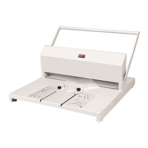
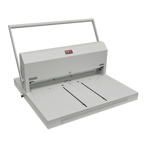
DE-BINDING METALBIND
1. Put the document on the machine (back cover up).
2. Push the extended back support maximally to the back. And disassemble moving limiter for
guide & bind bar.
3. Lift the handle (1) maximally up.
4. Open the document a few pages away from the back cover.
5. Fit the right edge of the de-binding wedge (5) in the right hook (4).
6
7. For de-binding channels 1,5 mm and 3 mm, use the de-binding adapter (5).
Place the de-binding adapter (5) on the channels, small slot is for 1,5 mm, bigger for 3 mm.
. Move the left end of the de-binding wedge (5) over the left hook (4) and fit it there.
8. Move the adjusting handle (2) to the right.
9. Press the handle (1) firmly down holding
the lever (2) at the same time.
Raise the handle (1) up, move the adjust-
ing lever (2) to the right and press the han-
dle (1) down again. Repeat for several
times.
10.
Lift the handle (1) up, loosen the adjusting
lever (2) and remove the document to-
gether with the wedge (5), then take the
wedge (5) out of the document carefully.
11.
12. Make the planned changes to the docu-
ment. The cover and channel may be re-
used (a maximum of three times).
6
DE-BINDING
C-BIND SYSTEM
Accessories enabling binding and de-binding of covers of the C-BIND system.
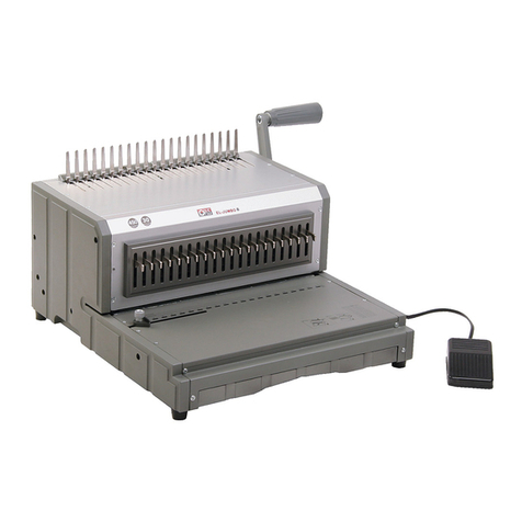
•2 binding inserts /A1 and B1/ in O.CB Inserts for Atlas 300/MB 300/MBE 300
(not included as standard) - (dig 1)
•de-binding wedge (dig 2) with AA jig (dig 3) in O.CB Debinding tool for Atlas 300/MB 300/MBE 300
(not included as standard)
7
A1
B1
Dig 1
back
cover
Dig 3
Dig 2
7
IMAGE PRESS DEVICE - SAFETY INSTRUCTIONS
Image Press device is available in OPUS offer.
•Before putting the machine into operation please read the safety precautions, manufac-
turer recommendations and the operation manual
•The operation manual should be easily available at any time for the operator
•The machine must not be placed near the heating units or ventilation units
•The machine should not be used in vicinity of inflammable liquids or gases
•The machine may be supplied only through the original cord. A mains socket must be
provided with efficient earthing. The supply voltage must be consistent with the para-
meters specified on the technical plate positioned on the machine housing. Disobeying
the above rule may result in electric shock or fire
•The supplying cable should be protected against any damage, must not be used to pull
the machine or to remove the plug from a socket
•Making any changes in the electric circuit or the supplying cable may result in electric
shock
•During a long standstill or before replacing the machine, the plug should be removed
from a mains socket
•Before replacing the machine it is necessary to check if the heater cooled down in order
to avoid destroying the surface on which the machine will be placed as well as avoid the burn
8
Atlas 300 mono •User’s guide GB
2. The bound documentation must have thickness of at least 1,8 mm (without cover). If the
documentation is thinner, it is obligatory to use filling strips (e.g. O•Filling Sticky avail-
able at OPUS), to increase the thickness of bound documents. When using channels up to
16 mm size and C sizes in C-BIND covers, put before binding both binding inserts A1 and
B1 to the binding slot and when using covers with size over 16 mm and C sizes in C-BIND
covers, put only one B1 insert into the binding slot.
3. When debinding C-BIND covers use debinding wedge included in O.CB Debinding Tool for
Atlas 300/MB 300/MBE 300.
IMPORTANT! When using AA covers put AA jig on spine of the cover.
4. Binding and de-binding of covers of the C-BIND system is performed analogous to binding
with Metalbind system, but: measure the thickness of sheet pile to be bound means of the
cover selection tool and select appropriate cover.
cover number of
dimension bound sheets
AA soft cover 15-40
hard cover 20-40
A 41-95
B 96-125
C 126-150
D 151-190
E 191-230
F 231-265
G 266-300
1. Choose the proper size of a
cover by using the table (on
the left) or the channel
width selecting tool (6).
1. Choose the proper size of a cover
by using the table (see above) or the
channel width selecting tool (7).
2. The dcuments to be bound must have
aminimumthicknessof1,8mmwithout
thecovers.Ifthedocumentsarethinner,
you must put a O.Filling Sticky which you
canbuyfromOPUS,toincreasethethicknessofthedocumentstobebound.ForA,B,Csizesin
C-bindcoversbeforebindingyoumusttbothbindingbarsA1&B1inthebindingslot.When
bindingallothersizesofC-Bindcovers,tonlyB1insertintothebindingslot.Depending
onamountofinsertsusedduringbinding,positionoftheextendedbacksupport(13)mustbe
changed.IfinthebindingslotthereisonlyB1Insert,theextendedbacksupportshouldbe
movedforward,InthecaseofbindingwithtwoinsertsA1andB1theextendedbacksupport(13)
should be move back.
3.Whende-bindingC-bindcoversusethede-bindingwedgewhichisavailablefromOPUS.pl,
for Atlas 300 / MB 300 / MBE 300.
INPORTANT:
When using AA covers put the AA remove word de-binding jig on spine of the cover first.
4. Binding and de-binding covers from the C-bind system is done in a similar way to the
Metalbindsystem.IntheC-Bindsystemyoumeasureonlythedocuments,notthedocuments
and covers. Use the cover selecting tool or the chart in this manual/user guide.
IMAGE PRESS DEVICE SAFETY INSTRUCTIONS
Image Press device is available in OPUS oer.
9
•BeforeputtingthemachineintooperationpleasereadtheHealth&Safetyprecautions,
manufacturer recommendations and the operation manual.
•Theoperationmanualshouldbeeasilyavailableatanytimefortheoperator.
•Theequipmentmustnotbeplacednearheatingorventilationunits.
•Theequipmentshouldnotbeusedinvicinityofinammableliquidsorgases.
•Theequipmentmaybesuppliedelectricityonlythroughtheoriginalcord.Amainssocketmust
be provided with ecient earthing. The supply voltage must be consistent with the parameters
speciedonthetechnicalplatepositionedontheequipmenthousing.Disobeyingtheabove
rulemayresultinelectricshockorre.
•Thepowersupplycableshouldbeprotectedagainstanydamage,andmustnotbeusedtopull
or remove the plug from the socket.
EN
7
Cover dimension Number of bound sheets
AA 5 mm 15 - 40
10 mm 41 - 90
B 13 mm 91 - 120
C 16 mm 121 - 145
D 20 mm 146 - 185
E 24 mm 186 - 230
F 28 mm 231 - 265
G 32 mm 266 - 300
6
DE-BINDING METALBIND
1. Put the document on the machine (back cover up).
2. Push the extended back support maximally to the back. And disassemble moving limiter for
guide & bind bar.
3. Lift the handle (1) maximally up.
4. Open the document a few pages away from the back cover.
5. Fit the right edge of the de-binding wedge (5) in the right hook (4).
6
7. For de-binding channels 1,5 mm and 3 mm, use the de-binding adapter (5).
Place the de-binding adapter (5) on the channels, small slot is for 1,5 mm, bigger for 3 mm.
. Move the left end of the de-binding wedge (5) over the left hook (4) and fit it there.
8. Move the adjusting handle (2) to the right.
9. Press the handle (1) firmly down holding
the lever (2) at the same time.
Raise the handle (1) up, move the adjust-
ing lever (2) to the right and press the han-
dle (1) down again. Repeat for several
times.
10.
Lift the handle (1) up, loosen the adjusting
lever (2) and remove the document to-
gether with the wedge (5), then take the
wedge (5) out of the document carefully.
11.
12. Make the planned changes to the docu-
ment. The cover and channel may be re-
used (a maximum of three times).
6
DE-BINDING
C-BIND SYSTEM
Accessories enabling binding and de-binding of covers of the C-BIND system.
•2 binding inserts /A1 and B1/ in O.CB Inserts for Atlas 300/MB 300/MBE 300
(not included as standard) - (dig 1)
•de-binding wedge (dig 2) with AA jig (dig 3) in O.CB Debinding tool for Atlas 300/MB 300/MBE 300
(not included as standard)
7
A1
B1
Dig 1
back
cover
Dig 3
Dig 1
B1
A1
