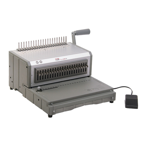
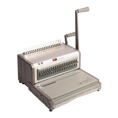
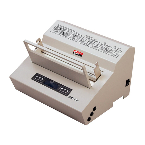
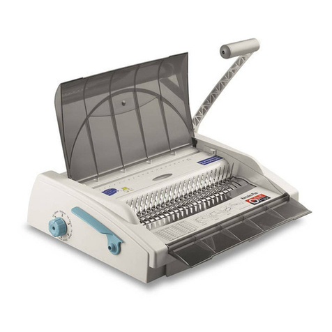
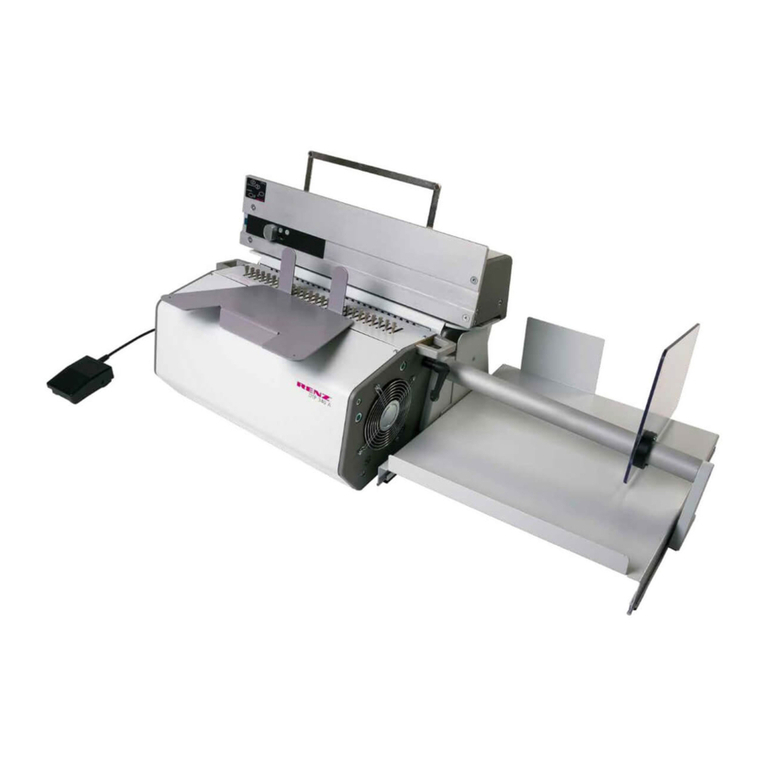
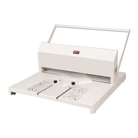
Opus MB 300 el-office User manual

MB 300 el-office | User’s Guide/Manual
1
MB 300 el-oce
GB | User’s Guide/Manual

2
Contents:
1. METALBIND System
2. Description
3. Health & Safety
4. Preparation to work
5. Pressure indicator
6. Binding (METALBIND)
7. De-binding (METALBIND)
8. C-Bind system
9. Technical data
1 | METALBIND System
MB 300 EL-OFFICE was designed for binding documents and covers using the metalbind system
of covers and channels. The pages of the presentation document are placed between covers and
then put into the MetalBind channel and clamped together from the outside.
The device is electrically assisted. After purchasing additional accessories it is possible to bind
C-Bind product. Operating requires no special qualications, however, before starting work, read
this manual.
Covers and pages are clamped together by a metal channel, which makes METALBIND most
durable binding system.
1 - The back wall of the channel is bent in to clamp covers and pages together.
2 - Special covering for hot print stamping.
3 - Shaped front edge to keep a perfect at face on the presentations.
4 - The internal pages protected against damage by the covers from the channel
5 - The front face of the channel is never misshaped always at
6 - The special protrusions at each end help to centre covers and papers of the presentation document and stop
them moving sideways in the channel
1
Metalbind
3
4
5
6
2

MB 300 el-office | User’s Guide/Manual
3
WARNING: MOVING PARTS, KEEP FINGERS AND HANDS AWAY FROM THE BINDING AREA.
• beforeoperatingtheequipmentpleasereadthehealth&safetyprecautions,manufacturer’s
recommendations and the operation manual.
• theoperationmanualshouldbeeasilyavailableatanytimefortheoperator.
• itisnecessarytooperatetheequipmentinaccordancewiththegeneralHealth&Safetyregulations.
• theequipmentshouldbeprotectedagainstdustandmoisture.
• theequipmentshouldbeplacedonastrongandstablesurface.
• donotplacetheequipmentclosetoheatingdevices.
• donotusetheequipmentclosetoammablematerialsandliquids.
• foruser’ssafety,theequipmentshouldbesuppliedpoweronlybytheoriginalcable.
1 - Start buttons
2 - Clamp lever
3 - Binding slot
4 - De-binding hooks
5 - Extended back support
6 - Main back support for adjustable
and stops and de-binding plate
7 - Channel size selector tool
8 - Adjustable end stop
9 - De-binding wedge tool MB 9a
CB 9b
10 - Storage for binding bars (A-B)and
De-binding wedge (MB) 9A,
11 - Channel slot:
12 - Binding strength indicator
2 | Description
3| Important Health & Safety
2 3
8
7
8
9A F
10 A/B
A/B B
C
C
CE E
D1 D2
11
6
5 4 4 12
1
A/B - Binding bars A small B Big C - banding bar
D1 - channel 5 - 32 mm D2 - channel 1.5; 3 mm E - Binding jaw
F - de-binding adapter for channels 1.5 and 3 mm only
1
5
2
6
3
7
4
8

4
•electricsocketmusthaveanearthandcomplywithearthingregulation.
•voltageratingshouldbeconsistentwithdataonthenameplateonthecoverandinthe
manual of the equipment. Disobeying this rule can cause electric shock and re, and cancel
the guarantee.
•itisnecessarytoprotectthecablefrombeingdamage.
•donotusethecabletomoveordisconnecttheequipmentfromthesocket.
•changesinelectricinstallationorthecablecancauseanelectricshock.
•toisolateorremovethecoverfromtheequipment,removethepowerplugfromthemains
socket.
•afuseprotectspowersystem,whichislocatedonthepowersupplyboardinsidetheequipment.
•ifitisnecessarytochangethefuse,useoneofthesamevolts,ampsandtype.
•ifthenewfuseblows,contactthesupplier.
•onepersonmustoperatetheequipmentonly.
•duringtheoperationprocess,otherpeoplemuststandclearoftheworkingarea.
•therearetwoseparateSTARTbuttonstoensuresafety.
•theequipmentworksonlywhenthetwobuttonsarepressedatthesametime.Whenthemotor
works, press one start button to stop it.
•keeptheequipmentawayfromthechildren.
•theequipmentcannotbeusedforanyotherpurposes,otherthanwhatitisdesignedforand
describedintheuser’sguide/manual.
•itisnecessarytocheckthattheequipmentisbeingoperatedcorrectlybeforecontactingthe
service department.
•theequipmentisdesignedtoworkcontinuouslyandshouldbeoperatedinroomtemperatures
above 8°C and up to +30°C.
•duringintensivework,itmaybenecessarytostopworktoallowthemotortocooldown,inthis
situation, the information will be display on the control panel.
•alwaysusetheequipmentinaccordancewiththeHealth&Safetyregulations.
•authorizedstamustcarryout,anyrepairswithintheguaranteeperiod.
•donotusesolventsorpetroleumbasedliquidstocleantheequipment.
4 | Preparation for work
•aftertakingthedeviceoutofthepackingbox,startassemblingtheequipment,attachthe
extended back support (5) on to the binding plate (6), to the pre drilled holes
•twobindingbarsAiBandDe-bindingwedge(9)areintheslotintheback.MagneticbarCput
in the binding slot.
•channelwidthselectingtool(7)youcanxtothemachinebyamagnet
The shape of the bars attached to the device (magnetic bar C and two binding bars A and B
is proled in such a way to help insert the documents into the channel. In addition,
the bindingbars A and B reduce the size of the binding slot. Bevore binding one of the
binding bars pot into the binding slot. Cut sides of the bars shoud be directly inside the
bining slot (3).

MB 300 el-office | User’s Guide/Manual
5
It allows you to control the clamping force channel and stores the value of this force in order to
achieve its repeatability.
5 | Indicator of the strength of binding
The display can be seen from 1 to 10, wherein the smallest possible force we
can set a 3 and the maximum is 10. Pressing the„+”or„-” causes change the
focus of half the value, for example, when the LED is on the top four this
means correcting the value 4, if the LED lights four of ve and this means
correcting the value 4.5, etc.
LED with a value of 1 indicates the direction of operation and so when:
•lights-themotorrunningforward
•ashing-themotorrunningbackwards
6 | Binding METALBIND
NOTE! WARNNING MOVING PARTS. WATCH THE FINGERS AND OTHER BODY PARTS.
1. Use channel width selecting tool (7) or table below to choose size of channel.
Channel sizes Number of pages per chancel for binding
H/p/H H/p/T S/p/S O/p/O
1,5 not available * not available* 1 - 9 1 - 9
3 not available * not available * 10 - 17 10 - 17
5 18 - 31 18 - 33 18 - 34 18 - 38
7 32 - 60 34 - 63 35 - 63 39 - 67
10 61 - 89 64 - 92 64 - 92 68 - 97
13 90 - 118 93 - 121 93 - 121 98 - 126
16 119 - 148 122 - 150 122 - 150 127 - 155
20 149 - 186 151 - 189 151 - 189 156 - 194
24 187 - 225 190 - 228 190 - 228 195 - 233
28 226 - 264 229 - 266 229 - 267 234 - 271
32 265 - 303 267 - 305 268 - 308 272 - 310
H/p/H - hard cover/ pages / hard cover
S/p/S - soft cover/ pages / soft cover
H/p/T - hard cover/ pages / transparent cover
O/p/O - no cover / pages / no cover
* channels 1.5 and 3mm are only
297mm long / not for binding
hard cover
MB 300 el-office | instrukcja obsługi
5
Kształt wkładek dołączonych do urządzenia: magnetycznej wkładki prowadzącej C oraz dwóch
wkładek bindujących A i B jest wyprolowany w taki sposób, aby ułatwić wkładanie dokumen-
-tacji do kanału. Dodatkowo wkładki bindujace A i B redukują wielkość szczeliny bindującej. Przed
przystąpieniem do bindowania jedną z wkładek bindujących (A lub B) należy umieścic przy płycie
debindującej. Ścięte boki obu wkładek powinny być skierowane do wnętrza szczeliny (3). Prawi-
dłowe ułożenie wkładek pokazuje rysunek wraz z przekrojem poprzecznym (na stronie z opisem
urządzenia).
Umożliwia kontrolę siły zacisku kanału oraz zapamiętuje wartość tej siły w celu uzyskania jej po-
wtarzalności.
5 | Wskaźnik siły bindowania
Na wskaźniku widać wartości od 1 do 10, przy czym najmniejsza możliwa siła jaką
możemy ustawić to 3, a największa to 10. Przyciśnięcie przycisku "+" lub "-" po-
woduje zmianę nastawu o połowę wartości i tak na przykład, gdy świeci się dioda
przy czwórce oznacza to nastawienie siły na wartość 4, jeśli dioda świeci się przy
czwórce i piątce oznacza to nastawienie siły na wartość 4,5 itp.
Dioda przy wartości 1 sygnalizuje kierunek pracy urządzenia i tak gdy:
• świeci - silnik działa do przodu
• miga - silnik działa do tyłu
6 | Bindowanie METALBIND
UWAGA NIEBEZPIECZNIE PORUSZAJĄCE SIĘ CZĘŚCI. UWAŻAĆ NA PALCE I INNE CZĘŚCI CIAŁA.
1. Przy pomocy przyrządu doboru rozmiaru kanału (7) zmierz grubość przeznaczonego do bin-
dowania pliku kartek i wybierz odpowiednią okładkę. Możliwe jest również dobranie rozmiaru
kanału za pośrednictwem poniższej tabeli.
Rozmiar kanału Ilość oprawianych kartek
T/k/T T/k/P M/k/M B/k/B
1,5 nie dotyczy* nie dotyczy* 1 - 9 1 - 9
3 nie dotyczy* nie dotyczy* 10 - 17 10 - 17
5 18 - 31 18 - 33 18 - 34 18 - 38
7 32 - 60 34 - 63 35 - 63 39 - 67
10 61 - 89 64 - 92 64 - 92 68 - 97
13 90 - 118 93 - 121 93 - 121 98 - 126
16 119 - 148 122 - 150 122 - 150 127 - 155
20 149 - 186 151 - 189 151 - 189 156 - 194
24 187 - 225 190 - 228 190 - 228 195 - 233
28 226 - 264 229 - 266 229 - 267 234 - 271
32 265 - 303 267 - 305 268 - 308 272 - 310
T/k/T – twarda okładka / plik kartek / twarda okładka
M/k/M – miękka okładka / plik kartek / miękka okładka
T/k/P – twarda okładka / plik kartek / przezroczysta okładka
B/k/B – plik kartek zbindowany jedynie za pomocą kanału
* kanały 1,5 i 3 mm dostępne są jedynie
w rozmiarze 297 mm i nie nadają się
do oprawy okładek twardych
6
Note! If the documents and covers are thinner, it is necessary to use a O.Filing sticky strips
avalible from OPUS suppies, to make it thick enough to bind. When useing channels 5 to 16
use binding bar B, and for channels 20-32 use binding bar (A) in the binding slot (3) before
you start binding.
2. Move the clamping lever (2) to the left till it stops
3. Depending bars (A or B) is used during binding position of the Extended back support (5) can
be adjusted accordingly. If diuring binding is in the bar A narrower liner, Extended back
support move up from each other, in the case of binding with a wider liner B Extended back
support (5) should be moved up to each other.
4. Set magnetic bar as shown in Figure 7 in Chapter 2. description of devices and accessories for
the channel size from 5 mm to 32 mm or in the position shown in Figure 8 in Chapter 2.
description of equipment and accessories for channels of size 1.5 and 3 mm.
5. Put the channel betwen the bars.
6. If you are using the channel A4 channel slide to the left to stop. Using the channel smaller than
A4, use stop moving (8). The position of the movable stop is dened using the scale on the
insert (position equal to half the length of the channel).
6.Closetheclamplever(2)totherightuntilyoucanfeelresistant’sonthelever.
7. Take the pile of documents insure they are even, put it between the covers, check the pages
are centred in relation to the edges of covers
8. Take the documents and covers and push carefully into the channel between the protrusions
in the binding slot. If the channels have parturitions, ensure covers are between them.
9.Use the„+” and„-”to set the binding force (see Chapter 5 | strength indicator binding)
Make sure the back of the cover is facing you.
BINDING
METALBIND
8. Ensure the papers and cover are in the right
order, now insert them into the binding slot (3)
and the back of the cover faces you.
Note:
•IfyouareusingaA4channel,notethatthepapers
must be inserted between the protrusions inside
the channel if they have protrusions.
9. Use the„+” or„-”to set the required binding
strength (see Chapter 5 | binding strength
indicator)
10. Press and release the 2 buttons together at the same time, you will hear a„beep”signal which
willSTARTthebindingprocess.TherstLEDlightsupandotherswillslowlystarttolightup
from 3, to the binding force that has been set in the previous step. The jaw will open and the
rst LED starts blinking, then they decrease till they all go out then the binding pressure you
set led comes on only which means that the binding process is completed.
11. Move the clamping lever (2) to the left so that you can take out the bound documentation.

MB 300 el-office | User’s Guide/Manual
7
7 | De binding METALBIND
For de-binding cover, remove the adjustable stop from the back plate.
1. To De-bind documents bound with 1.5 mm or 3 mm channels, rst put
them into the special plastic de-binding tool. Then go to the next step.
2. To De-bind documents bound with 5 mm to 16 mm channels, place the
bound book at with the back cover facing up, place the de-bind tool
about 6 pages in with the at side down, close the book.
(See the diagram opposite)
3. To De-bind documents bound with channel bigger than 16 mm, place
the bound book at with the back cover facing up on the equipment
and place the de-bind tool level with the de-binding hooks at side
down, close the book.
(See the diagram opposite)
WARNING! When De-binding books with channels 28 mm and 32 mm remove the extend back
support (5) from the main back support (6).
4. Move the clamp lever (2) to the right, until you feel resistance, then set the de-binding strength
to 3.
5.Holdingtheclamplever(2)nowpressthetwoSTARTbuttons(1)ifthechannelisnot
de-bound move the clamp lever further to the right still holding the lever (2) press the two
start buttons again, if it is still not de-bound repeat the process till the book is de-bound.
6.Removethede-bindingtool(9)fromthehooks(4)thengentlyremoveitfrombetween
the pages.
7. Make the changes to the documentation.
8. To re-bind, you can use the same covers and channel, up to three times.
Warning!
If you do not remove the slack with the clamping lever (2) or used the wrong channel with
insucient documents, jaw will move forward and go back without binding. The LEDs
described in step 9, will not light up and the rst LED will not blink. Wait until the equipment
stop and try again.
Note:
At any time during operation of the equipment you can perform the following operations:
• PAUSE
- By pressing one of the START buttons you will hear a „beep” signal and the motor will stop.
After this pressing one button will cause no reaction.
• CHANGE OF DIRECTION
- By pressing two START buttons, you will hear a„beep”signal and jaw direction will change.
16
13
10
7
MINI

8
DE-BINDING METALBIND
back cover
8 | C-BIND System
Accessories for binding and De-binding covers from the C-BIND system:
•Channelsizeselectiontool(7)
•O•CBInsertsforAtlas300/MB300,bindinginsertstools(A1andB1)(Fig.1)
•O•CBDe-bindingToolforAtlas300/MB300/MBE300–de-bindingtool(Fig.2)andde-binding
tool for AA covers (Fig. 3)
Binding and de-binding C-Bind cover.
C-BIND is bound and de-bound in the same
way as the METALBIND system. Using the
channel size selection tool measure the
documents, then select the cover or use the
chart on the left.
WARNING! In the case of de-binding AA
covers, use the special tool, included in the
kit called O.CB De-binding Tool for Atlas
300/MB 300 / MBE 300, which must be put
on the spine.
Note:
At any time during operation of the equipment
you can perform the following operations:
• PAUSE
- By pressing one of the START buttons you will
hear a„beep” signal and the motor will stop. After
this pressing one button will cause no reaction.
• CHANGE OF DIRECTION
- By pressing two START buttons, you will hear
a„beep”signal and jaw direction will change.
A1
B1 9B
Channel sizes How many sheets can be
bound
AA soft cover 15 - 40
hard cover 20 - 40
A 41 - 95
B 96 - 125
C 126 - 150
D 151 - 190
E 191 - 230
F 231 - 265
G 266 - 300
1
2 3

MB 300 el-office | User’s Guide/Manual
9
9 | Technical data
•powersupply.......................................................................................................220-240Volts:50/60Hz;0.3A
•powerconsumption:............................................................................................................................................60W
•themaximumjawpressure:.......................................................................................................................2.3tons
•workingtemperature:..................................................................................................................................0-30°C
•themaximumbindingcapacity:....................................................................................................................300*
•netweight:..........................................................................................................................................................21.0kg
•grossweight:......................................................................................................................................................23.4kg
•dimensions(HxWxD):........................................................................................................270x465x320mm
* tested on paper 80g / m2
Equipment and products marked with this symbol cannot be deposed of together with normal
waste, including municipal waste. The user is required to take their used product to a collection
point for the recycling of waste electrical and electronic equipment. Proper segregation of used
equipment reduces the negative impact of hazardous substances that may be in there, on the
environment and human health. For more detailed information concerning the disposal of used
equipment, please contact your local authority, waste disposal service or the point of sale where
you purchased the product. By ensuring proper disposal of equipment we are helping to protect
the environment.
Minimum thickness documents must be more than 1.8 mm (without cover) If the documents are
thinner,youmustuseallingstrip(eg.O•FillingStickysuppliedbyOPUS)sizeupto16mm(C),
use the C-BIND insert tools (A1 and B1) for sizes more than 16 mm (C) use only B1 in the binding
slot.
Depending on the thickness of the document used the extended back support (5) it can be
adjusted accordingly. If using B1 insert move the extended back support towards you fully,
for inserts A1 B1 move the extended back support away from you fully.
08. 09. 2016 OPUS Sp. z o. o., ul. Toruńska 8, 44 - 122 Gliwice www.opus.pl

10
Other manuals for MB 300 el-office
1
Table of contents
Other Opus Binding Machine manuals

Opus
Opus Hercules Plus User manual

Opus
Opus MB 300 User manual

Opus
Opus Easy 120 User manual

Opus
Opus Atlas 190 User manual

Opus
Opus multiCREASE 52 User manual

Opus
Opus OFFICERINO User manual

Opus
Opus Wire Bono User manual

Opus
Opus Atlas 300 mono User manual

Opus
Opus Atlas 300 mono User manual

Opus
Opus MB 300 User manual

Opus
Opus MBE-300 User manual

Opus
Opus COIL BONO User manual

Opus
Opus profiBINDER&CLOSER User manual

Opus
Opus MultiCREASE 30 User manual

Opus
Opus Wire Bono User manual

Opus
Opus MultiPress 52 User manual

Opus
Opus MBE-300 User manual

Opus
Opus El Jumbo B User manual

Opus
Opus Atlas 190 User manual

Opus
Opus TB 250 User manual