1,
o
10.
11.
12.
13.
14.
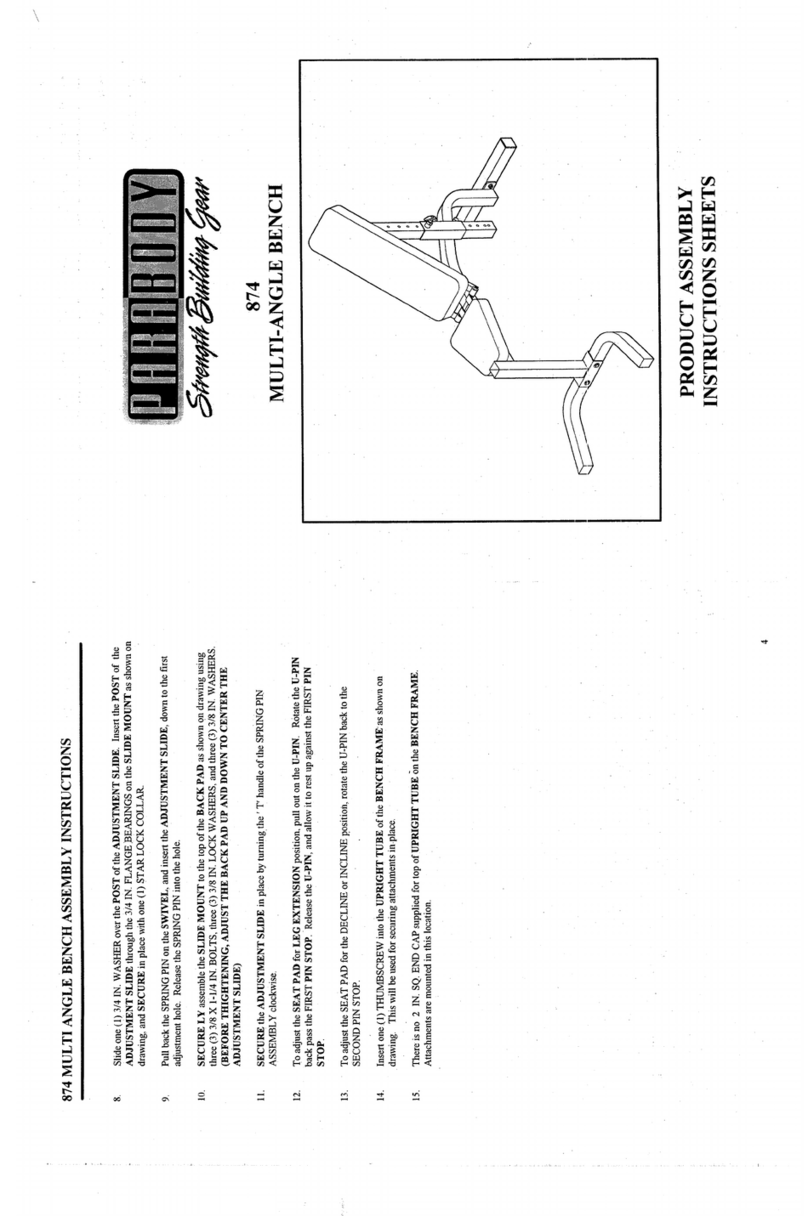
Insert one (1) 3 X2 IN. ENDCAPinto the top of the UPRIGtITFRAME,and two (2) 2 IN. SQ.
CAPSinto the BASEof the UPRIGHTFRAMEas shownon drawing. Repeat this step for the second
UPRIGHT FRAME.
SECURELYassemble both UPRIGHTFRAMESto the CROSSBRACEas shown on drawing using
four (4) 1/2 X3 IN. BOLTS,four (4) 1/2 IN. WASHERS,and four (4) 1/2 IN. LOCK
(IMPORTANT: ~ ANGLE BRACKETS ON ~ CROSS BRACE ARE OFFSET, PLEASE
MAKESURE THAT ~ LONGEST END OF TIlE BRACKET IS FACING IYP BEFORE
ASSEMBLY)
SECURELYassemble the BENCHFRAMEto the CROSSBRACEas shown on dmw~ngusing two (2)
1/2 X3 IN. BOLTS,two (2) 1/2 IN. WASHERS,and two (2) 1/2 IN. LOCKNUTS.Attach one 2"
cover cap to the BENCHFRAMEas shown.
Insert two (2) 1/2 IN. FLANGEBEARINGSinto each end of the BUSHINGof the BLENCHFRAME
shown on drawing.
SECURELYassemble the BENCHSLIDE to the BUSHINGof the BENCHFRAMEas shown on
drawing, using one (1) 1/2 X 3-1/2 IN. BOLTone (1) 1/2 IN. LOWHTLOCK
Attach eight (8) 1-1/2 X 3/4" GLIDESto the WOLFFSLEEVE(FOURONEACHEll’D) as shown
(DETAILA) using the following steps:
¯Thoroughlyclean all surfaces wherethe GLIDESare to be attached.
¯Removethe GLIDESfrom the paper backing and f’mrdy apply themto all shownsurfaces.
Insert one (1) U-PINthrough the BUSItlNGof the WOLFFSLEEVEas shown on ctrawing, and attach
one (1) PALNUTto the end of the U-PIN.
SECURELYAssemble one (1) SPRINGPIN ASSEMBLYto the SPRINGPIN BARI~’,L, of the
WOLFFSLEEVEas shown in (DETAIL B). (!!! IMPORTANT!!! TIGHTENTLTE NUTOF
SPRING PIN ASSEMBLYSECURELY)
Pull back the SPRINGPINon the WOLFFSLEEVEand slide it over the end of the BENCHSLIDEas
shownon drawing. Engagethe SPRINGPIN into one of the adjustment holes. Secure tk~e WOLFF
SLEEVEin place with one (1) 3-PRONGKNOB.
LOOSELYassemble one (1) 3 PRONGKNOBto the UPRIGHTTUBEof the BENCI~[ FRAME
shown on drawing. (TI:[IS WILL BE USED TO SECUREATTACHMENTSIN PLACE)
Attach one (1) 1-1/4 IN. SQ. RUBBERBUMPERto the SLIDESUPPORTas shown orb drawing.
SECURELYassemble the SLIDESUPPORTto the end of the BENCHSLIDEas shown on drawing
using one (1) 3/8 X 2-3/4 IN. BOLT,two (2) 3/8 IN WASHERS,and one (1) 3/8 IN. LOCK
Attach two (2) 1 X 1 GLIDESto file top of the BENCHFRAMEwhere the SLIDESUPPORTmakes
contact. See drawing.
Assemble the SEATPADto the WOLFFSLEEVE,start by sliding t~vo (2) HINGETABSover the
PIN of the WOLFFSLEEVE(ONE ONEACHSIDE) as shown on drawing, and SECURELY
assemble each tlINGE TABto the SEATPAll using two (2) 3/8 X 1-1/4 IN. BOLTSmid two (2)
IN. WASHERS.(MAKE SURE BOTHltINGE TABS ARE ALL THE WAYON TIlE PIN)
Part # 6657601 3 Revision: it0/28/96
