manuals.online logo
Brands
  1. Home
  2. •
  3. Brands
  4. •
  5. Pfeiffer Vacuum
  6. •
  7. Control Unit
  8. •
  9. Pfeiffer Vacuum EVI 005 MI User manual

Pfeiffer Vacuum EVI 005 MI User manual

BP 5118 BEN (2010-06)
A PASSION
FOR PERFECTION
EVI 005 MI
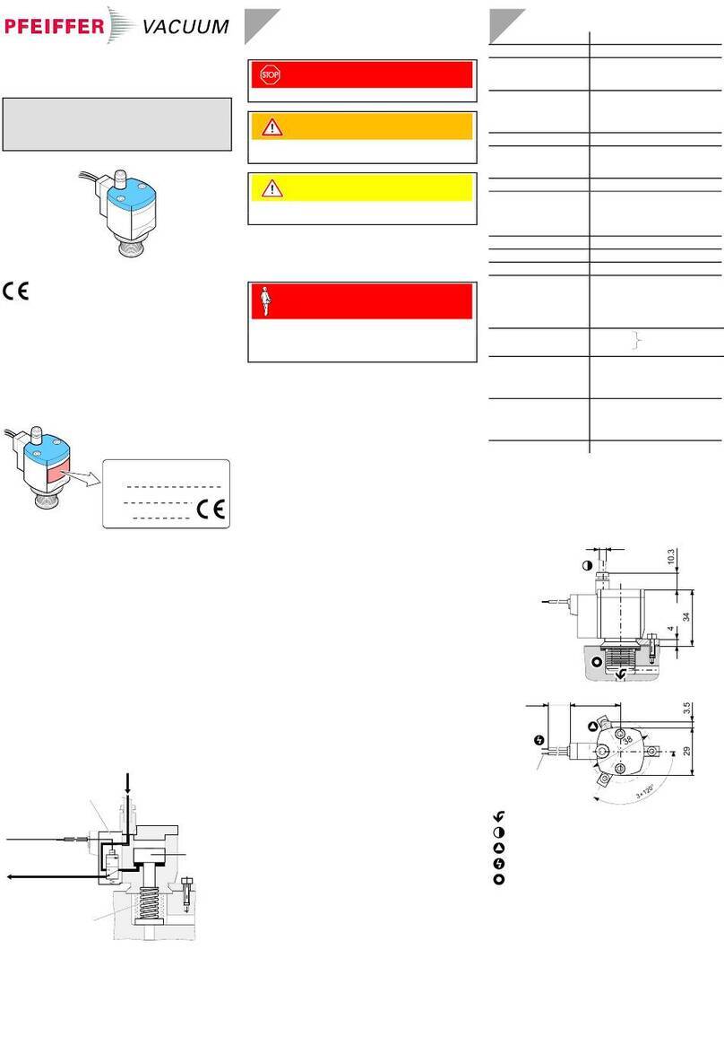
Insert Valve, electromagnetically actuated
Operating Instructions
Product Identification
In all communications with Pfeiffer Vacuum, please specify
the information on the product nameplate. For convenient
reference copy that information into the space provided
below.
F-No:
Pfeiffer Vacuum, D-35614 Asslar
V=, W
D-35614 Asslar Berliner Strasse 43
Validity
This document applies to products with part number
PF H13 241.
The part number (No.) can be taken from the product name-
plate.
We reserve the right to make technical changes without prior
notice.
Intended Use
The insert valve is predominantly used in fast-cycling vacuum
systems, for example, for gas analysis and coating proc-
esses.
Functional Principle
The EVI 005 MI is opened by the solenoid coil and closed by
the prestressed pressure spring. It will close, or remain
closed, on power loss.
Safety
Symbols Used
DANGER
Information on preventing any kind of physical injury.
WARNING
Information on preventing extensive equipment and en-
vironmental damage.
Caution
Information on correct handling or use. Disregard can lead
to malfunctions or minor equipment damage.
Personnel Qualifications
Skilled personnel
All work described in this document may only be carried
out by persons who have suitable technical training and
the necessary experience or who have been instructed by
the end-user of the product.
General Safety Instructions
•Adhere to the applicable regulations and take the neces-
sary precautions for the process media used.
Consider possible reactions between the materials
(→"Technical Data") and the process media.
Consider possible reactions of the process media due to
the heat generated by the product.
•Adhere to the applicable regulations and take the neces-
sary precautions for all work you are going to do and con-
sider the safety instructions in this document.
•Before beginning to work, find out whether any vacuum
components are contaminated. Adhere to the relevant re-
gulations and take the necessary precautions when hand-
ling contaminated parts.
Communicate the safety instructions to all other users.
Liability and Warranty
Pfeiffer Vacuum assumes no liability and the warranty be-
comes null and void if the end-user or third parties
•disregard the information in this document
•use the product in a non-conforming manner
•make any kind of interventions (modifications, alterations
etc.) on the product
•use the product with accessories not listed in the corres-
ponding product documentation.
The end-user assumes the responsibility in conjunction with
the process media used.
Failures due to contamination or wear and tear, as well as
expendable parts (e.g. seals), are not covered by the
warranty.
Technical Data
Version normally closed
Nominal diameter 5 mm
Threaded connection M20 × 1
Power specifications
Nominal voltage
Nominal power
24 VDC ±10%
10 W
Duty cycle 100% (i.e. continuous duty possible)
Degree of protection IP 65
Mounting orientation any
Switching frequency max.
Cycles to first main-
tenance
300 / min 1)
>2'000'000 2)
Tightness 1×10⁻⁹ mbar l/s
Resistance to pressure 1×10⁻⁸ mbar … 10 bar (absolute)
Operating pressure 1×10⁻⁸ mbar … 1 bar
Pressure difference Δp
In closing direction
In opening direction
Opens against a pressure
difference Δp
5 bar
1.5 bar
1 bar (with 24 VDC)
Closing time
Opening time
7 ms 1)
30 ms 1)
Temperature
Ambiance 5 °C
3) … 40 °C
Heat generation 60 °C (after 1¼ hours on con-
tinuous duty and at an ambient
temperature of 25 °C)
Bakeout 120 °C (with idle solenoid coil)
150 °C (without solenoid coil)
Materials
Bellows, connection
nut
Actuator
Seals
stainless steel 1.4301
stainless steel 1.4105
FPM
Weight 0.2 kg
1) With pressure difference Δp = 0 bar.
2) Under clean operating conditions.
If the valve is operated under harsh or dirty conditions, it
should be cleaned / maintained before the specified service
time to maintenance has been reached.
3) –15 °C, if the ambiance is free of condensable gases.
Dimensions [mm]
48
300 32
0.38 mm2
(AWG 22)
41
1
M20×1
Recommended flow direction
Electrical connection
Protective lid (vacuum connection)
Installation
Vacuum Connection
Caution
Caution: vacuum component
Dirt and damages impair the function of the
vacuum component.
When handling vacuum components, take ap-
propriate measures to ensure cleanliness and
prevent damages.
Caution
Caution: dirt sensitive area
Touching the product or parts thereof with bare
hands increases the desorption rate.
Always wear clean, lint-free gloves and use
clean tools when working in this area.
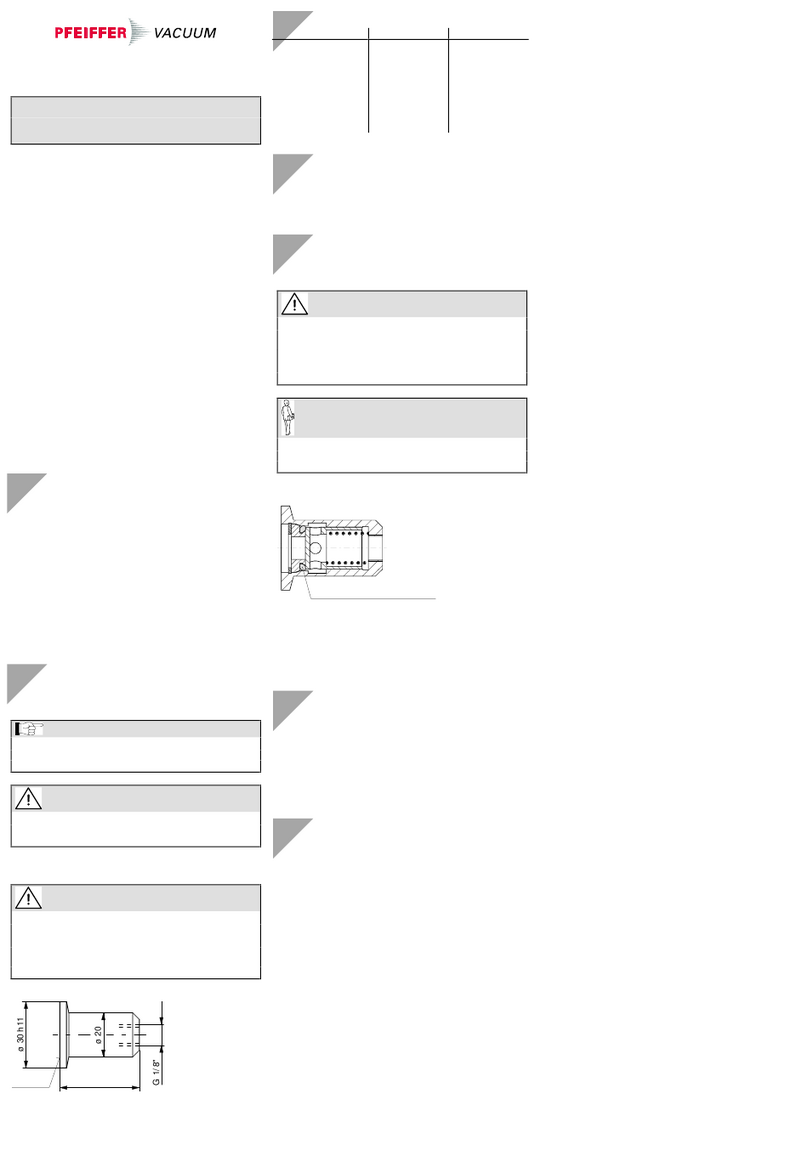
nPreparing the valve seat.
Without burr
(eg. R0.2)
M20×1
ø14
ø5
N6C
N6C
R0.6
6.5+0.05
0
≤ø5
6
3
7.5
R1
N6C
Machining sign:
centrically machined and roughness
value ≤0.8 μm (N6)
oRemove the protective lid, hexagon nut, and solenoid
coil.
Keep the protective lid.
pRemove the protective lid from the guiding tube.
The armature and pressure spring can drop
out. Be careful when removing the protective
lid.
6.5 mm
Guiding tube
Pressure spring
Armature
The armature needs to be in an specific po-
sition to be introduced into the guiding tube or
removed there from.
Lock the armature by turning it (≈180°).
qScrew the guiding tube (with armature, pressure spring,
and O-rings) onto the prepared valve seat until the me-
chanical stop is reached.
rSlide the solenoid coil onto the guiding tube and turn it
until the power connection is in the required position,
then tighten the connection nut.
Tightening torque
≤3 Nm
sPlace the protective lid.
Power Connection
The power connection is established via the two cable
strands. Adhere to the local regulations with regard to the
installation.
Caution
Caution: switching of inductive loads (solenoid
coil)
Inductive loads may considerably reduce the
service life of or even destroy contacts.
Preferably a clamping diode should be connec-
ted in parallel to the solenoid coil. The polarity
should be chosen in such a way that the diode
blocks when normal operating voltage is avail-
able.
Clamping diode Solenoid coil
Contact
0,38 mm2
(AWG 22)
Operation
The product is ready for operation as soon as it has been
installed.
Version: Normally closed.
°C
DANGER
DANGER: hot surface
Touching the hot surface (>55 °C) can cause
burns.
Wear protective gloves.
bp5118ben
(2010-06)
Original: German BP 5118 BDE (2010-06)
Deinstallation
DANGER
DANGER: contaminated parts
Contaminated parts can be detrimental to health
and environment.
Before beginning to work, find out whether any
parts are contaminated. Adhere to the relevant
regulations and take the necessary precautions
when handling contaminated parts.
Caution
Caution: vacuum component
Dirt and damages impair the function of the
vacuum component.
When handling vacuum components, take ap-
propriate measures to ensure cleanliness and
prevent damages.
Caution
Caution: dirt sensitive area
Touching the product or parts thereof with bare
hands increases the desorption rate.
Always wear clean, lint-free gloves and use
clean tools when working in this area.
Preconditions:
•Vacuum system vented
•Valve cooled down to <55 °C
nDisconnect the product from the power source.
Before connecting or disconnecting the
product, turn off the control system.
oRemove the protective lid.
pRemove the hexagon nut and the solenoid coil.
qUnscrew the guiding tube.
The armature and pressure spring can drop
out. Be careful when removing the guiding
tube.
Maintenance, Repair
Under clean operating conditions the product requires no
maintenance during the rated cycle life.
Failures due to contamination or wear and tear, as
well as expendable parts (e.g. seals), are not
covered by the warranty.
DANGER
DANGER: contaminated parts
Contaminated parts can be detrimental to health
and environment.
Before beginning to work, find out whether any
parts are contaminated. Adhere to the relevant
regulations and take the necessary precautions
when handling contaminated parts.
Caution
Caution: vacuum component
Dirt and damages impair the function of the
vacuum component.
When handling vacuum components, take ap-
propriate measures to ensure cleanliness and
prevent damages.
Caution
Caution: dirt sensitive area
Touching the product or parts thereof with bare
hands increases the desorption rate.
Always wear clean, lint-free gloves and use
clean tools when working in this area.
Precondition: Valve deinstalled.
nDisassemble the guiding tube, armature, and pressure
spring.
Guiding tube
Pressure spring
Armature
oRemove the O-rings.
When reassembling the product: be careful to
insert the O-rings level into the grooves
without twisting them.
Guiding tube
Armature
O-ring, FPM
ø3.63×2.62 mm
O-ring, FPM
ø14×1.78 mm
ZClean the valve and replace its parts (→"Spare
Parts").
DANGER
DANGER: cleaning agents
Cleaning agents can be detrimental to
health and environment.
Adhere to the relevant regulations and
take the necessary precautions when
handling cleaning agents and disposing of
them. Consider possible reactions with the
product materials.
•Carefully clean the parts with a grease solving, non-
scouring cleaner.
•After cleaning, the parts should preferably be rinsed
with alcohol and subsequently heated to ≈50 °C in
an oven or with an industrial blower.
•Carefully clean the sealing surfaces with a lint-free
cloth moistened with alcohol. Allow them to dry.
•Wipe the seals with a lint-free cloth slightly
moistened with vacuum oil.
[Proceed in reverse order to reassemble the valve.
After reassembly, a few switching cycles should be
performed in order for the O-rings to perfectly adapt
to the sealing surfaces.
Spare Parts
When ordering spare parts, always indicate:
•All information on the product nameplate
•Description and ordering number according to the spare
parts list
Ordering number
Seal kit, comprising
5× O-ring, FPM 75, ø1.78×1.78 1)
5× O-ring, FPM 75, ø7.66×1.78 1)
5× O-ring, FPM 75, ø3.63×2.62
5× O-ring, FPM 75, ø14×1.78
PT 130 165-T
1) Not required for his valve
Ordering number
Spare parts kit, comprising
1× solenoid coil 24 VDC / 10 W 1)
1× pressure spring
1× O-ring, FPM 75, ø7.66×1.78 mm
1× O-ring, FPM 75, ø14×1.78 mm
1× O-ring, FPM 75, ø3.63×2.62 mm
BN 841 321-T
1) The included hexagonal nut is not needed
Returning the Product
WARNING
WARNING: forwarding contaminated products
Contaminated products (e.g. radioactive, toxic,
caustic or biological hazard) can be detrimental
to health and environment.
Products returned to Pfeiffer Vacuum should
preferably be free of harmful substances. Ad-
here to the forwarding regulations of all involved
countries and forwarding companies and en-
close a duly completed declaration of contami-
nation *).
*) Form under www.pfeiffer-vacuum.net
Products that are not clearly declared as "free of harmful
substances" are decontaminated at the expense of the
customer.
Products not accompanied by a duly completed declaration
of contamination are returned to the sender at his own
expense.
Disposal
DANGER
DANGER: contaminated parts
Contaminated parts can be detrimental to health
and environment.
Before beginning to work, find out whether any
parts are contaminated. Adhere to the relevant
regulations and take the necessary precautions
when handling contaminated parts.
N
WARNING
WARNING: substances detrimental to the en-
vironment
Products or parts thereof (mechanical and elec-
tric components, operating fluids etc.) can be de-
trimental to the environment.
Dispose of such substances in accordance with
the relevant local regulations.
Separating the components
After disassembling the product, separate its components
according to the following criteria:
•Contaminated components
Contaminated components (radioactive, toxic, caustic, or
biological hazard etc.) must be decontaminated in accor-
dance with the relevant national regulations, separated
according to their materials, and disposed of.
•Other components
Such components must be separated according to their
materials and recycled.
Berliner Straße 43
D–35614 Asslar
Deutschland
Tel +49 (0) 6441 802-0
Fax +49 (0) 6441 802-202
[email protected]
www.pfeiffer-vacuum.net
Other Pfeiffer Vacuum Control Unit manuals

Pfeiffer Vacuum TPG 256 A User manual

Pfeiffer Vacuum

Pfeiffer Vacuum TPG 256 A User manual

Pfeiffer Vacuum PM Z01 310 User manual

Pfeiffer Vacuum

Pfeiffer Vacuum PM Z01 310 User manual

Pfeiffer Vacuum DVB Series User manual

Pfeiffer Vacuum

Pfeiffer Vacuum DVB Series User manual

Pfeiffer Vacuum TPG 300 User manual

Pfeiffer Vacuum

Pfeiffer Vacuum TPG 300 User manual

Pfeiffer Vacuum EVL 016 P User manual

Pfeiffer Vacuum

Pfeiffer Vacuum EVL 016 P User manual

Pfeiffer Vacuum PM Z01 290 User manual

Pfeiffer Vacuum

Pfeiffer Vacuum PM Z01 290 User manual

Pfeiffer Vacuum DualGauge TPG 262 User manual

Pfeiffer Vacuum

Pfeiffer Vacuum DualGauge TPG 262 User manual

Pfeiffer Vacuum EVA 016S User manual

Pfeiffer Vacuum

Pfeiffer Vacuum EVA 016S User manual

Pfeiffer Vacuum AVA 016 User manual

Pfeiffer Vacuum

Pfeiffer Vacuum AVA 016 User manual

Pfeiffer Vacuum UVH 016 VI User manual

Pfeiffer Vacuum

Pfeiffer Vacuum UVH 016 VI User manual

Pfeiffer Vacuum EVA 016 H User manual

Pfeiffer Vacuum

Pfeiffer Vacuum EVA 016 H User manual

Pfeiffer Vacuum UDV 040 User manual

Pfeiffer Vacuum

Pfeiffer Vacuum UDV 040 User manual

Pfeiffer Vacuum EVB 063 PA User manual

Pfeiffer Vacuum

Pfeiffer Vacuum EVB 063 PA User manual

Pfeiffer Vacuum EVB Series User manual

Pfeiffer Vacuum

Pfeiffer Vacuum EVB Series User manual

Pfeiffer Vacuum TVV 001 User manual

Pfeiffer Vacuum

Pfeiffer Vacuum TVV 001 User manual

Pfeiffer Vacuum TPG 366 MAXIGAUGE User manual

Pfeiffer Vacuum

Pfeiffer Vacuum TPG 366 MAXIGAUGE User manual

Pfeiffer Vacuum RME 005 A User manual

Pfeiffer Vacuum

Pfeiffer Vacuum RME 005 A User manual

Pfeiffer Vacuum UHV 016 CU User manual

Pfeiffer Vacuum

Pfeiffer Vacuum UHV 016 CU User manual

Pfeiffer Vacuum DCU 002 User manual

Pfeiffer Vacuum

Pfeiffer Vacuum DCU 002 User manual

Pfeiffer Vacuum TPG 500 User manual

Pfeiffer Vacuum

Pfeiffer Vacuum TPG 500 User manual

Pfeiffer Vacuum PM Z01 295 User manual

Pfeiffer Vacuum

Pfeiffer Vacuum PM Z01 295 User manual

Pfeiffer Vacuum EVB 016 Series User manual

Pfeiffer Vacuum

Pfeiffer Vacuum EVB 016 Series User manual

Pfeiffer Vacuum EVB 016 PA User manual

Pfeiffer Vacuum

Pfeiffer Vacuum EVB 016 PA User manual

Pfeiffer Vacuum TC 110 User manual

Pfeiffer Vacuum

Pfeiffer Vacuum TC 110 User manual

Popular Control Unit manuals by other brands

Yoshitake AL-250 product manual

Yoshitake

Yoshitake AL-250 product manual

SIGLENT SEM5000A Series quick start

SIGLENT

SIGLENT SEM5000A Series quick start

Festo VIFB-21 Series manual

Festo

Festo VIFB-21 Series manual

Beninca Logica24 operating instructions

Beninca

Beninca Logica24 operating instructions

Sony DSBK-100 operating instructions

Sony

Sony DSBK-100 operating instructions

Bardac drives T2-ENCOD-IN user guide

Bardac drives

Bardac drives T2-ENCOD-IN user guide

Samson 41-23 Series Mounting and operating instructions

Samson

Samson 41-23 Series Mounting and operating instructions

Infineon GPT12 Timer Concatenation 1 manual

Infineon

Infineon GPT12 Timer Concatenation 1 manual

Spears LXT-3A-0107 installation instructions

Spears

Spears LXT-3A-0107 installation instructions

handtmann 12605 operating manual

handtmann

handtmann 12605 operating manual

schmersal Elan SRB 201ZH X3 operating instructions

schmersal

schmersal Elan SRB 201ZH X3 operating instructions

Toshiba GN-4020 manual

Toshiba

Toshiba GN-4020 manual

WEG CFW100 series Installation, configuration and operations guide

WEG

WEG CFW100 series Installation, configuration and operations guide

Siemens SINAMICS S120 Commissioning manual

Siemens

Siemens SINAMICS S120 Commissioning manual

SMC Networks IL220 Series Operation manual

SMC Networks

SMC Networks IL220 Series Operation manual

Active Audio NUT-RC user guide

Active Audio

Active Audio NUT-RC user guide

ALT Aquabrass ThermOne 61234 installation guide

ALT

ALT Aquabrass ThermOne 61234 installation guide

LOVATO ELECTRIC GEX69-C Series manual

LOVATO ELECTRIC

LOVATO ELECTRIC GEX69-C Series manual

manuals.online logo
manuals.online logoBrands
  • About & Mission
  • Contact us
  • Privacy Policy
  • Terms and Conditions

Copyright 2025 Manuals.Online. All Rights Reserved.