manuals.online logo
Brands
  1. Home
  2. •
  3. Brands
  4. •
  5. Pfeiffer Vacuum
  6. •
  7. Control Unit
  8. •
  9. Pfeiffer Vacuum UVH 040 CU User manual

Pfeiffer Vacuum UVH 040 CU User manual

BP 5276 BEN (2010-10)
A PASSION
FOR PERFECTION
UVH 016 … 063 CU
All-Metal Angle Valve, manually actuated, bellows
sealed, metal valve seat seal
Instruction Sheet
Produktidentifikation
In all communications with Pfeiffer Vacuum, please specify
the information on the product nameplate. For convenient
reference copy that information into the space provided
below.
Typ:
No:
F-No:
Pfeiffer Vacuum, D-35614 Asslar
Validity
This document applies to products with the following part
numbers:
PFK32032 (UVH 016 CU DN 16 CF)
PFK52032 (UVH 040 CU DN 40 CF)
PFK62032 (UVH 063 CU DN 63 CF)
The part number (No) can be taken from the product name-
plate.
If not indicated otherwise in the legends, the illustrations in
this document correspond to the valve with the nominal
diameter DN 40. They apply to valves with other nominal
diameters by analogy.
We reserve the right to make technical changes without prior
notice.
Intended Use
The product is used as shut-off valve for XHV and UHV appli-
cations. It can be baked out at 300 °C. The welded housing
is suited for high-purity and toxic gases.
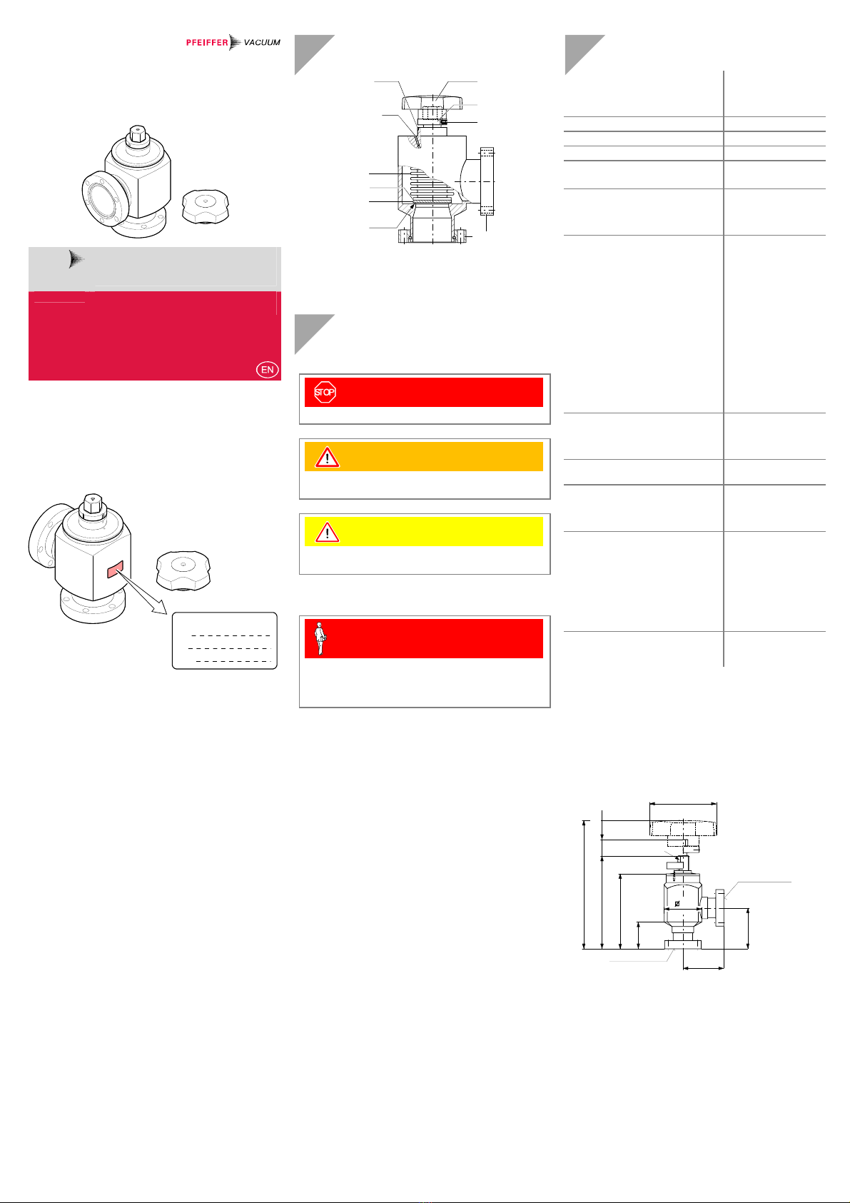
Description
Valve plate
Bellows
Valve plate base
CF flange
DN 16 ... 63 CF-R
(rotatable)
Rotary knob
(enclosed)
Mark on the valve
housing
Leak detection bore
Adjustment ring
Hex socket set
screw
Sealing edge
Safety
Symbols Used
DANGER
Information on preventing any kind of physical injury.
WARNING
Information on preventing extensive equipment and en-
vironmental damage.
Caution
Information on correct handling or use. Disregard can lead
to malfunctions or minor equipment damage.
Personnel Qualifications
Skilled personnel
All work described in this document may only be carried
out by persons who have suitable technical training and
the necessary experience or who have been instructed by
the end-user of the product.
General Safety Instructions
•Adhere to the applicable regulations and take the nec-
essary precautions for the process media used.
Consider possible reactions between the materials
(→"Technical Data") and the process media.
•Adhere to the applicable regulations and take the nec-
essary precautions for all work you are going to do and
consider the safety instructions in this document.
•Before beginning to work, find out whether any vacuum
components are contaminated. Adhere to the relevant
regulations and take the necessary precautions when
handling contaminated parts.
Communicate the safety instructions to all other users.
Liability and Warranty
Pfeiffer Vacuum assumes no liability and the warranty be-
comes null and void if the end-user or third parties
•disregard the information in this document
•use the product in a non-conforming manner
•make any kind of interventions (modifications, alterations
etc.) on the product
•use the product with accessories not listed in the corre-
sponding product documentation.
The end-user assumes the responsibility in conjunction with
the process media used.
Failures due to contamination or wear and tear, as well as
expendable parts (e.g. seals), are not covered by the
warranty.
Technical Data
Connection flanges, rotatable
UVH 016 CU
UVH 040 CU
UVH 063 CU
DN 16 CF-R
DN 40 CF-R
DN 63 CF-R
Installation angle any
Flow direction any
Tightness 1×10-12 mbar l/s
Pressure range (absolute)
Bursting pressure
1×10-11 mbar … 4 bar
8 bar
Conductance 1)
UVH 016 CU
UVH 040 CU
UVH 063 CU
3 l/s
38 l/s
100 l/s
Temperatures
Ambiance
Operation
Bakeout
(without rotary knob, closed,
pressure in vacuum system
<1×10⁻⁴ mbar or vacuum
system vented with inert gas)
Rotary knob
Continuous
Temporary
Storage
Temperature increase
UVH 016 CU
UVH 040 CU
UVH 063 CU
0 °C … 55 °C
≤300 °C
≤300 °C
≤80 °C
80 … 110 °C
+5 … +45 °C
-15 … +45 °C 2)
≤4 °C/minute
≤4 °C/minute
≤2 °C/minute
Closing torque
UVH 016 CU
UVH 040 CU
UVH 063 CU
2 … 10 Nm
8 … 30 Nm
30 … 60 Nm
Service life of sealing plate
(cold closing operations)
1000 cycles 3)
Lift (opening)
UVH 016 CU
UVH 040 CU
UVH 063 CU
12 mm
23 mm
33 mm
Materials
Housing / spindle flange
Spindle
Bellows
Valve plate base
Valve plate
Forming ring
Sealing plate
Rotary knob
stainless steel 1.4301
CuSn8 2.1030.26
stainless steel 1.4541
st. steel 1.4301 ESU
stainless steel 1.4301
copper
PA 15% GF
Weight
UVH 016 CU / UVH 040 CU
UVH 063 CU
0.4 kg / 2.0 kg
5.0 kg
1) For air with molecular flow.
2) Ambiance free of condensable gases.
3) Cycles without expandable parts (seals) and under clean
operating conditions.
If the valve is operated under harsh or dirty conditions, it
should be cleaned / maintained before the specified service
time to maintenance has been reached.
Dimensions [mm]
69.6
25.6
88.2
AF 8
38
38
35
ø 62
DN 16 CF-R
(rotatable)
UVH 016 CU
DN 16 CF-R
(rotatable)
119.4
Spindle lift
15
63
63
70
107.6
34.6
Spindle lift
27
140
ø 62
DN 40 CF-R
(rotatable)
UVH 040 CU
DN 40 CF-R
(rotatable)
177.5
AF 17
105
105
Spindle lift
36
210.7
ø100
61
267.6
ø74
DN 63 CF-R
(rotatable)
UHV 063 CU
DN 63 CF-R
(rotatable)
182
AF 22
Installation
Caution
Caution: vacuum component
Dirt and damages impair the function of the
vacuum component.
When handling vacuum components, take
appropriate measures to ensure cleanliness and
prevent damages.
Caution
Caution: dirt sensitive area
Touching the product or parts thereof with bare
hands increases the desorption rate.
Always wear clean, lint-free gloves and use
clean tools when working in this area.
Caution
Caution: factory adjustment
The valve is delivered
•with the adjustment ring set to the closing
torque.
•with the valve plate lying on the sealing edge
without being pressed against it (which en-
sures optimum storage).
Bear in mind that the valve is not tight in this
condition. Do not loosen the adjustment ring nor
perform any opening or closing action until the
valve is put into operation.
The protective packaging should not be removed until shortly
before installation. Even the slightest contamination could
cause leaks.
Installation
Space Requirements
Make sure the valve can be operated without any risk of
bodily injury.
Spindle lift
UVH 016 CU 15 mm
UVH 040 CU 27 mm
UVH 063 CU 36 mm
Spindle lift
Flange Connection
Seal
Hex nut
Hex head
screw
Washer
Protective lid
CF flange
Keep the protective lids.
Flange Seal Pieces Ordering
number
DN 16 CF copper
copper, silver-plated
10
10
PF 501 401-T
PF 501 501-T
DN 40 CF copper
copper, silver-plated
10
10
PF 501 404-T
PF 501 504-T
DN 63 CF copper
copper, silver-plated
10
10
PF 501 406-T
PF 501 506-T
Flange Hex head
screw
Number of
screws
Required torque
DN 16 CF M4 × 20 mm 6 per flange 4 Nm
DN 40 CF M6 × 35 mm 6 per flange 10 Nm
DN 63 CF M8 × 50 mm 6 per flange 20 Nm
Start-Up
Bakeout
It is good practice to bake out new valves and valves the
inner parts of which have been exposed to atmosphere for
some time, e.g. with a heating sleeve.
DANGER
DANGER: hot surface
Touching the hot surface (>55 °C) can cause
burns.
Put the product out of operation and allow it to
cool down.
Caution
Caution: bakeout at atmosphere
Baking out with the inner parts of the valve ex-
posed to atmosphere may lead to the formation
of oxides and thus cause leaks.
Bake out the valve only if
•the pressure in the vacuum system is
<1×10⁻⁴ mbar or
•the vacuum system has been vented with
inert gas.
Caution
Caution: bakeout temperatures >80 °C
The rotary knob may be continually exposed to
temperatures <80 °C only.
Remove the rotary knob before baking out the
valve.
Close the valve …
Using a ring wrench, turn the hex head until mark con the
adjustment ring is in line with the mark on the valve housing.
90°
Mark on valve housing
… and bake it out.
p < 10-4 mbar
or vacuum system
vented with inert gas
p < 10-4 mbar
or vacuum system
vented with inert gas
Temperature increase:
DN 016 ≤4 °C/minute
DN 040 ≤4 °C/minute
DN 063 ≤2 °C/minute
Maximum bakeout
temperature: 300 °C
Heating sleeve
The valve is closed and ready for use now.
bp5276ben
(2010-10)
Original: German BP 5276 BDE (2010-10)
Operation
Prevent the entry of dirt, dust, or other abrasive contamina-
tion into the valve. Even very small particles on the sealing
surfaces may cause leaks.
°C
DANGER
DANGER: hot surface
Touching the hot surface (>55 °C) can cause
burns.
Wear protective gloves.
Caution
Caution: bakeout at atmosphere
Baking out with the inner parts of the valve ex-
posed to atmosphere may lead to the formation
of oxides and thus cause leaks.
Bake out the valve only if
•the pressure in the vacuum system is
<1×10⁻⁴ mbar or
•the vacuum system has been vented with
inert gas.
Caution
Caution: position of the adjustment ring
Closing the valve with an incorrectly set adjust-
ment ring may cause damages.
Close the valve with the minimum torque using a
torque wrench. Check that the valve is tight. If it
is not yet tight, gradually increase the closing
torque in small steps (Δα ≈5°) until the valve is
tight. Do not exceed the maximum closing
torque.
Closing torque
minimum maximum
UVH 016 CU 2 Nm 10 Nm
UVH 040 CU 8 Nm 30 Nm
UVH 063 CU 30 Nm 60 Nm
Closing the Angle Valve
nOperating temperature >55 °C
Using a ring wrench, position the valve plate on the
sealing edge by turning the hex head clockwise until
an increased resistance can be felt.
Turn until an in-
creased resistance
can be felt.
°C
Operating temperature ≤55 °C
Position the valve plate on the sealing edge by
turning the rotary knob clockwise until an increased
resistance can be felt. Remove the rotary knob.
Turn until an
increased
resistance
can be felt.
enclosed
oClose the valve by turning the hex head clockwise with
a ring wrench until mark con the adjustment ring is in
line with the mark on the valve housing. Remove the
ring wrench.
Use the ring wrench
only temporarily.
°C >55 °C
Mark on valve housing
pCheck that the valve is tight. If it is not yet tight, keep
gradually turning the hex head in small steps (Δα ≈5°)
until the valve is tight. However, do not turn the hex
head any further when mark don the adjustment ring
is in line with the mark on the valve housing (α= 90°).
Caution
Caution: maximum closing torque
The maximum closing torque (mark don
the adjustment ring is in line with the mark
on the valve housing) must not be ex-
ceeded. If the maximum torque is ex-
ceeded, the sealing surfaces of the valve
and/or spindle may get damaged.
When the maximum closing torque has
been reached, it is recommended to ex-
change the valve plate before running any
further processes (→[1]).
αmax = 90°
Δα ≈5°
Mark on valve housing
A leak test must be performed if in a process
•the temperature was significantly increased
by the heater and/or due to the process
itself
•the bakeout time was significantly in-
creased.
Opening the Angle Valve
The maximum opening of the valve is limited by a
mechanical stop.
nOpen the valve by turning the hex head counter-clock-
wise with a ring wrench until the resistance decreases.
Remove the ring wrench.
Use the ring wrench
only temporarily.
°C >55 °C
Turn until the resistance
decreases.
oOperating temperature >55 °C
Continue opening the valve by turning the hex head
counter-clockwise with the ring wrench. Remove the
ring wrench.
Continue opening.
Use the ring wrench
only temporarily.
°C
Operating temperature <55 °C
Continue opening the valve by turning the rotary
knob counter-clockwise. Remove the rotary knob.
Continue
opening.
Deinstallation
DANGER
DANGER: contaminated parts
Contaminated parts can be detrimental to health
and environment.
Before beginning to work, find out whether any
parts are contaminated. Adhere to the relevant
regulations and take the necessary precautions
when handling contaminated parts.
Caution
Caution: vacuum component
Dirt and damages impair the function of the
vacuum component.
When handling vacuum components, take ap-
propriate measures to ensure cleanliness and
prevent damages.
Vent the vacuum system and wait until the valve has
cooled down to <50 °C.
Detach the flanges and put the protective lids in place.
CF flange
Hex nut
Hex head
screw
Washer
Protective lid
Seal
When the valve is reinstalled, replacing the seals is
recommended (→"Installation").
Maintenance/Repair
→[1]
Storage
Caution
Caution: vacuum component
Inappropriate storage leads to an increase of the
desorption rate and/or may result in mechanical
damage of the product.
•Cover the vacuum ports of the product with
protective lids or grease free aluminum foil.
•Close the valve with the rotary knob until an
increased resistance can be felt. The valve
plate is now lying on the sealing edge without
being pressed against it (which ensures opti-
mum storage).
•Do not exceed the admissible storage tem-
perature range (→"Technical Data").
Returning the Product
WARNING
WARNING: forwarding contaminated products
Contaminated products (e.g. radioactive, toxic,
caustic or biological hazard) can be detrimental
to health and environment.
Products returned to Pfeiffer Vacuum should
preferably be free of harmful substances. Ad-
here to the forwarding regulations of all involved
countries and forwarding companies and en-
close a duly completed declaration of contami-
nation *).
*) Form under www.pfeiffer-vacuum.net
Products that are not clearly declared as "free of harmful
substances" are decontaminated at the expense of the
customer.
Products not accompanied by a duly completed declaration
of contamination are returned to the sender at his own
expense.
Disposal
DANGER
DANGER: contaminated parts
Contaminated parts can be detrimental to health
and environment.
Before beginning to work, find out whether any
parts are contaminated. Adhere to the relevant
regulations and take the necessary precautions
when handling contaminated parts.
N
WARNING
WARNING: substances detrimental to the
environment
Products or parts thereof (mechanical and
electric components, operating fluids etc.) can
be detrimental to the environment.
Dispose of such substances in accordance with
the relevant local regulations.
Separating the components
After disassembling the product, separate its components
according to the following criteria:
•Contaminated components
Contaminated components (radioactive, toxic, caustic, or
biological hazard etc.) must be decontaminated in accor-
dance with the relevant national regulations, separated
according to their materials, and disposed of.
•Other components
Such components must be separated according to their
materials and recycled.
Further Information
[1] www.pfeiffer-vacuum.net
Operating Instructions
All-metal Angle Valve UVH 016 … 063 CU
BP 5275 BDE (German)
BP 5275 BEN (English
Pfeiffer Vacuum GmbH, D–35614 Asslar,
Deutschland
Berliner Straße 43
D–35614 Asslar
Deutschland
Tel +49 (0) 6441 802-0
Fax +49 (0) 6441 802-202
[email protected]
www.pfeiffer-vacuum.net

This manual suits for next models

2

Other Pfeiffer Vacuum Control Unit manuals

Pfeiffer Vacuum TPG 500 User manual

Pfeiffer Vacuum

Pfeiffer Vacuum TPG 500 User manual

Pfeiffer Vacuum TPG 366 MAXIGAUGE User manual

Pfeiffer Vacuum

Pfeiffer Vacuum TPG 366 MAXIGAUGE User manual

Pfeiffer Vacuum BVML User manual

Pfeiffer Vacuum

Pfeiffer Vacuum BVML User manual

Pfeiffer Vacuum TPG 366 MAXIGAUGE User manual

Pfeiffer Vacuum

Pfeiffer Vacuum TPG 366 MAXIGAUGE User manual

Pfeiffer Vacuum HISCROLL User manual

Pfeiffer Vacuum

Pfeiffer Vacuum HISCROLL User manual

Pfeiffer Vacuum DualGauge TPG 262 User manual

Pfeiffer Vacuum

Pfeiffer Vacuum DualGauge TPG 262 User manual

Pfeiffer Vacuum EVA 016 H User manual

Pfeiffer Vacuum

Pfeiffer Vacuum EVA 016 H User manual

Pfeiffer Vacuum EVR 116 User manual

Pfeiffer Vacuum

Pfeiffer Vacuum EVR 116 User manual

Pfeiffer Vacuum EVB 063 PA User manual

Pfeiffer Vacuum

Pfeiffer Vacuum EVB 063 PA User manual

Pfeiffer Vacuum EVI 105 PI User manual

Pfeiffer Vacuum

Pfeiffer Vacuum EVI 105 PI User manual

Pfeiffer Vacuum TPG 361 User manual

Pfeiffer Vacuum

Pfeiffer Vacuum TPG 361 User manual

Pfeiffer Vacuum EVL 016 P User manual

Pfeiffer Vacuum

Pfeiffer Vacuum EVL 016 P User manual

Pfeiffer Vacuum EVB 016 Series User manual

Pfeiffer Vacuum

Pfeiffer Vacuum EVB 016 Series User manual

Pfeiffer Vacuum PM Z01 290 User manual

Pfeiffer Vacuum

Pfeiffer Vacuum PM Z01 290 User manual

Pfeiffer Vacuum EVN 116 User manual

Pfeiffer Vacuum

Pfeiffer Vacuum EVN 116 User manual

Pfeiffer Vacuum UVH 016 VI User manual

Pfeiffer Vacuum

Pfeiffer Vacuum UVH 016 VI User manual

Pfeiffer Vacuum EVB 160 PA User manual

Pfeiffer Vacuum

Pfeiffer Vacuum EVB 160 PA User manual

Pfeiffer Vacuum DCU 002 User manual

Pfeiffer Vacuum

Pfeiffer Vacuum DCU 002 User manual

Pfeiffer Vacuum EVB 016 S A/X User manual

Pfeiffer Vacuum

Pfeiffer Vacuum EVB 016 S A/X User manual

Pfeiffer Vacuum PM Z01 295 User manual

Pfeiffer Vacuum

Pfeiffer Vacuum PM Z01 295 User manual

Pfeiffer Vacuum UHV 016 CU User manual

Pfeiffer Vacuum

Pfeiffer Vacuum UHV 016 CU User manual

Pfeiffer Vacuum UDV 146 User manual

Pfeiffer Vacuum

Pfeiffer Vacuum UDV 146 User manual

Pfeiffer Vacuum TCP 350 User manual

Pfeiffer Vacuum

Pfeiffer Vacuum TCP 350 User manual

Pfeiffer Vacuum OmniControl User manual

Pfeiffer Vacuum

Pfeiffer Vacuum OmniControl User manual

Popular Control Unit manuals by other brands

SEW-Eurodrive 18979297 operating instructions

SEW-Eurodrive

SEW-Eurodrive 18979297 operating instructions

Telebyte GHN-AT-PROG-UPLC-3-SLOPE reference guide

Telebyte

Telebyte GHN-AT-PROG-UPLC-3-SLOPE reference guide

Bosch GCY 30-4 Professional Original instructions

Bosch

Bosch GCY 30-4 Professional Original instructions

V2 EASY-TOP Series manual

V2

V2 EASY-TOP Series manual

Advantech PCM-3345 manual

Advantech

Advantech PCM-3345 manual

GCAN GC-4642 user manual

GCAN

GCAN GC-4642 user manual

Lenze E94AZHY0025 Mounting instructions

Lenze

Lenze E94AZHY0025 Mounting instructions

ISYGLT DA-04-VX Technical Data/Instruction Manual

ISYGLT

ISYGLT DA-04-VX Technical Data/Instruction Manual

Trox Technik ATVC-100 installation manual

Trox Technik

Trox Technik ATVC-100 installation manual

Meinberg IMS-VSI Setup Guide Manual

Meinberg

Meinberg IMS-VSI Setup Guide Manual

MOULDPRO TCU-200 User guideline

MOULDPRO

MOULDPRO TCU-200 User guideline

VAT 590 Series Installation, operating,  & maintenance instructions

VAT

VAT 590 Series Installation, operating, & maintenance instructions

Keysight Technologies N3301A Programming guide

Keysight Technologies

Keysight Technologies N3301A Programming guide

Jung 4093 KRM TS D Operation manual

Jung

Jung 4093 KRM TS D Operation manual

Compaq KN310 Installation Card

Compaq

Compaq KN310 Installation Card

CALEFFI QuickSetter+ 132 Series user guide

CALEFFI

CALEFFI QuickSetter+ 132 Series user guide

Pacbrake PowerHalt PH2 installation manual

Pacbrake

Pacbrake PowerHalt PH2 installation manual

Inovance GR10-EC-6SW user guide

Inovance

Inovance GR10-EC-6SW user guide

manuals.online logo
manuals.online logoBrands
  • About & Mission
  • Contact us
  • Privacy Policy
  • Terms and Conditions

Copyright 2025 Manuals.Online. All Rights Reserved.