Roller Uni-Press E User manual

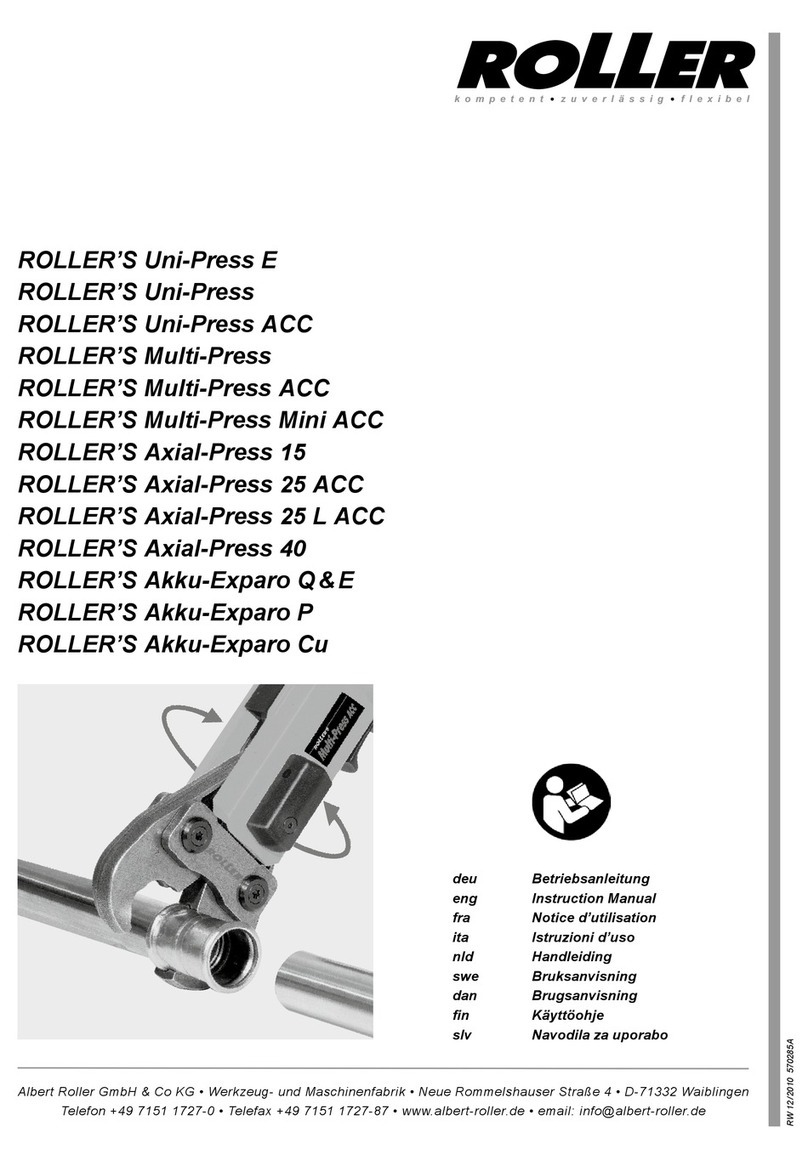
ROLLER’S Uni-Press E
ROLLER’S Uni-Press
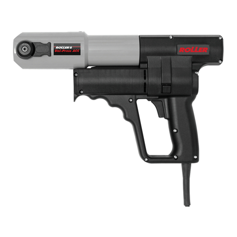
ROLLER’S Uni-Press ACC
ROLLER’S Multi-Press
ROLLER’S Multi-Press ACC
ROLLER’S Multi-Press Mini ACC
ROLLER’S Axial-Press 15
ROLLER’S Axial-Press 40
ROLLER’S Akku-Exparo Q&E
deu Betriebsanleitung
eng Instruction Manual
fra Notice d’utilisation
ita Istruzioni d’uso
nld Handleiding
swe Bruksanvisning
dan Brugsanvisning
fin Käyttöohje
slv Navodila za uporabo
Albert Roller GmbH & Co KG • Werkzeug- und Maschinenfabrik • Neue Rommelshauser Straße 4 • D-71332 Waiblingen
Telefon +49 7151 1727-0 • Telefax +49 7151 1727-87 • www.albert-roller.de • email: info@albert-roller.de
S 02 / 10 570285 A
kompetent ●zuverlässig ●flexibel

Fig. 1
13
1
A B
2
12
12
1110 4 5
6
8
9
3
Fig. 2 9
6
7 8
6
6
618 15
8
8
8
9
14
15
13
9
9
Fig. 6
Fig. 8
16
17
18
6
14
8
13
9
Fig. 7
13
8
Fig. 3
6
13
13
9
8
Fig. 4
Fig. 5
16

Fig. 9
Fig. 11
Fig. 10
Fig. 12
Fig. 13
Fig. 14
4G
S
PR
A B
B
A
B
A 19
20 21

deu deu
Originalbetriebsanleitung
Allgemeine Sicherheitshinweise
ACHTUNG! Sämtliche Anweisungen sind zu lesen. Fehler bei der Einhaltung der
nachstehend aufgeführten Anweisungen können elektrischen Schlag, Brand und/
oder schwere Verletzungen verursachen. Der nachfolgend verwendete Begriff
„elektrisches Gerät“ bezieht sich auf netzbetriebene Elektrowerkzeuge (mit Netz-
kabel), auf akkubetriebene Elektrowerkzeuge (ohne Netzkabel), auf Maschinen und
auf elektrische Geräte. Verwenden Sie das elektrische Gerät nur bestimmungsgemäß
und unter Beachtung der allgemeinen Sicherheits- und Unfallverhütungsvorschriften.
BEWAHREN SIE DIESE ANWEISUNGEN GUT AUF.
A) Arbeitsplatz
a) Halten Sie Ihren Arbeitsbereich sauber und aufgeräumt. Unordnung und
unbeleuchtete Arbeitsbereiche können zu Unfällen führen.
b) Arbeiten Sie mit dem elektrischen Gerät nicht in explosionsgefährdeter
Umgebung, in der sich brennbare Flüssigkeiten, Gase oder Stäube benden.
Elektrische Geräte erzeugen Funken, die den Staub oder die Dämpfe entzünden
können.
c) Halten Sie Kinder und andere Personen während der Benutzung des elek-
trischen Gerätes fern. Bei Ablenkung können Sie die Kontrolle über das Gerät
verlieren.
B) Elektrische Sicherheit
a) Der Anschlussstecker des elektrischen Gerätes muss in die Steckdose
passen. Der Stecker darf in keiner Weise verändert werden. Verwenden Sie
keine Adapterstecker gemeinsam mit schutzgeerdeten elektrischen Geräten.
Unveränderte Stecker und passende Steckdosen verringern das Risiko eines
elektrischen Schlages. Ist das elektrische Gerät mit Schutzleiter ausgerüstet,
darf es nur an Steckdosen mit Schutzkontakt angeschlossen werden. Betreiben
Sie das elektrische Gerät auf Baustellen, in feuchter Umgebung, im Freien oder
bei vergleichbaren Aufstellarten nur über eine 30mA-Fehlerstrom-Schutzeinrich-
tung (FI-Schalter) am Netz.
b) Vermeiden Sie Körperkontakt mit geerdeten Oberächen, wie von Rohren,
Heizungen, Herden und Kühlschränken. Es besteht ein erhöhtes Risiko durch
elektrischen Schlag, wenn Ihr Körper geerdet ist.
c) Halten Sie das Gerät von Regen oder Nässe fern. Das Eindringen von Wasser
in ein Elektrogerät erhöht das Risiko eines elektrischen Schlages.
d) Zweckentfremden Sie das Kabel nicht, um das Gerät zu tragen, aufzuhängen
oder um den Stecker aus der Steckdose zu ziehen. Halten Sie das Kabel fern
von Hitze, Öl, scharfen Kanten oder sich bewegenden Geräteteilen. Beschä-
digte oder verwickelte Kabel erhöhen das Risiko eines elektrischen Schlages.
e) Wenn Sie mit einem elektrischen Gerät im Freien arbeiten, verwenden Sie
nur Verlängerungskabel, die auch für den Außenbereich zugelassen sind.
Die Anwendung eines für den Außenbereich geeigneten Verlängerungskabels
verringert das Risiko eines elektrischen Schlages.
C) Sicherheit von Personen
Diese Geräte sind nicht bestimmt für die Benutzung von Personen (einschließ-
lich Kindern) mit verminderten physischen, sensorischen oder geistigen
Fähigkeiten, oder mangelnder Erfahrung und Wissen, es sei denn, sie
wurden über die Benutzung des Gerätes von einer für ihre Sicherheit
verantwortlichen Person instruiert oder kontrolliert. Kinder müssen kontrol-
liert werden, um sicherzustellen, dass sie nicht mit dem Gerät spielen.
a) Seien Sie aufmerksam, achten Sie darauf, was Sie tun, und gehen Sie mit
Vernunft an die Arbeit mit einem elektrischen Gerät. Benutzen Sie das
elektrische Gerät nicht, wenn Sie müde sind oder unter dem Einuss von
Drogen, Alkohol oder Medikamenten stehen. Ein Moment der Unachtsamkeit
beim Gebrauch des Gerätes kann zu ernsthaften Verletzungen führen.
b) Tragen Sie persönliche Schutzausrüstung und immer eine Schutzbrille.
Das Tragen persönlicher Schutzausrüstung, wie Staubmaske, rutschfeste Sicher-
heitsschuhe, Schutzhelm oder Gehörschutz, je nach Art und Einsatz des elekt-
rischen Gerätes, verringert das Risiko von Verletzungen.
c) Vermeiden Sie eine unbeabsichtigte Inbetriebnahme. Vergewissern Sie sich,
dass der Schalter in der Position „AUS“ ist, bevor Sie den Stecker in die
Steckdose stecken. Wenn Sie beim Tragen des elektrischen Gerätes den Finger
am Schalter haben oder das Gerät eingeschaltet an die Stromver sorgung anschließen,
kann dies zu Unfällen führen. Überbrücken Sie niemals den Tippschalter.
d) Entfernen Sie Einstellwerkzeuge oder Schraubenschlüssel, bevor Sie das
elektrische Gerät einschalten. Ein Werkzeug oder Schlüssel, der sich in einem
drehenden Geräteteil bendet, kann zu Verletzungen führen. Greifen Sie niemals
in sich bewegende (umlaufende) Teile.
e) Überschätzen Sie sich nicht. Sorgen Sie für einen sicheren Stand und halten
Sie jederzeit das Gleichgewicht. Dadurch können Sie das Gerät in unerwarteten
Situationen besser kontrollieren.
f) Tragen Sie geeignete Kleidung. Tragen Sie keine weite Kleidung oder
Schmuck. Halten Sie Haare, Kleidung und Handschuhe fern von sich
bewegenden Teilen. Lockere Kleidung, Schmuck oder lange Haare können von
sich bewegenden Teilen erfasst werden.
g) Wenn Staubabsaug- und -auffangeinrichtungen montiert werden können,
vergewissern Sie sich, dass diese angeschlossen sind und richtig verwendet
werden. Das Verwenden dieser Einrichtungen verringert Gefährdungen durch Staub.
h) Überlassen Sie das elektrische Gerät nur unterwiesenen Personen. Jugend-
liche dürfen das elektrische Gerät nur betreiben, wenn sie über 16 Jahre alt sind,
dies zur Erreichung ihres Ausbildungszieles erforderlich ist und sie unter Aufsicht
eines Fachkundigen gestellt sind.
D) Sorgfältiger Umgang und Gebrauch von elektrischen Geräten
a) Überlasten Sie das elektrische Gerät nicht. Verwenden Sie für Ihre Arbeit
das dafür bestimmte elektrische Gerät. Mit dem passenden elektrischen Gerät
arbeiten Sie besser und sicherer im angegebenen Leistungsbereich.
b) Benutzen Sie kein elektrisches Gerät, dessen Schalter defekt ist. Ein elek-
trisches Gerät, das sich nicht mehr ein- oder ausschalten lässt, ist gefährlich und
muss repariert werden.
c) Ziehen Sie den Stecker aus der Steckdose, bevor Sie Geräteeinstellungen
vornehmen, Zubehörteile wechseln oder das Gerät weglegen. Diese Vorsichts-
maßnahme verhindert den unbeabsichtigten Start des Geräts.
d) Bewahren Sie unbenutzte elektrische Geräte außerhalb der Reichweite von
Kindern auf. Lassen Sie Personen das elektrische Gerät nicht benutzen,
die mit diesem nicht vertraut sind oder diese Anweisungen nicht gelesen
haben. Elektrische Geräte sind gefährlich, wenn sie von unerfahrenen Personen
benutzt werden.
e) Pegen Sie das elektrische Gerät mit Sorgfalt. Kontrollieren Sie, ob beweg-
liche Geräteteile einwandfrei funktionieren und nicht klemmen, ob Teile
gebrochen oder so beschädigt sind, dass die Funktion des elektrischen
Gerätes beeinträchtigt ist. Lassen Sie beschädigte Teile vor dem Einsatz
des elektrischen Gerätes von qualiziertem Fachpersonal oder von einer
autorisierten ROLLER Vertrags-Kundendienstwerkstatt reparieren. Viele
Unfälle haben ihre Ursache in schlecht gewarteten Elektrowerkzeugen.
f) Halten Sie Schneidwerkzeuge scharf und sauber. Sorgfältig gepegte Schneid-
werkzeuge mit scharfen Schneidkanten verklemmen sich weniger und sind leichter
zu führen.
g) Sichern Sie das Werkstück. Benutzen Sie Spannvorrichtungen oder einen
Schraubstock, um das Werkstück festzuhalten. Es ist damit sicherer gehalten
als mit Ihrer Hand, und Sie haben außerdem beide Hände zur Bedienung des
elektrischen Gerätes frei.
h) Verwenden Sie elektrische Geräte, Zubehör, Einsatzwerkzeuge usw. entspre-
chend diesen Anweisungen und so, wie es für diesen speziellen Gerätetyp
vorgeschrieben ist. Berücksichtigen Sie dabei die Arbeitsbedingungen und
die auszuführende Tätigkeit. Der Gebrauch von elektrischen Geräten für andere
als die vorgesehenen Anwendungen kann zu gefährlichen Situationen führen.
Jegliche eingenmächtige Veränderung am elektrischen Gerät ist aus Sicherheits-
gründen nicht gestattet.
E) Sorgfältiger Umgang und Gebrauch von Akkugeräten
a) Stellen Sie sicher, dass das elektrische Gerät ausgeschaltet ist, bevor Sie
den Akku einsetzen. Das Einsetzen eines Akkus in ein elektrisches Gerät, das
eingeschaltet ist, kann zu Unfällen führen.
b) Laden Sie die Akkus nur in Ladegeräten auf, die vom Hersteller empfohlen
werden. Für ein Ladegerät, das für eine bestimmte Art von Akkus geeignet ist,
besteht Brandgefahr, wenn es mit anderen Akkus verwendet wird.
c) Verwenden Sie nur die dafür vorgesehenen Akkus in den elektrischen
Geräten. Der Gebrauch von anderen Akkus kann zu Verletzungen und Brand-
gefahr führen.
d) Halten Sie den nicht benutzten Akku fern von Büroklammern, Münzen,
Schlüsseln, Nägeln, Schrauben oder anderen kleinen Metallgegenständen,
die eine Überbrückung der Kontakte verursachen könnten. Ein Kurzschluss
zwischen den Akkukontakten kann Verbrennungen oder Feuer zur Folge haben.
e) Bei falscherAnwendung kann Flüssigkeit aus demAkku austreten. Vermeiden
Sie den Kontakt damit. Bei zufälligem Kontakt mit Wasser abspülen. Wenn
die Flüssigkeit in die Augen kommt, nehmen Sie zusätzlich ärztliche Hilfe
in Anspruch. Austretende Akkuüssigkeit kann zu Hautreizungen oder Verbren-
nungen führen.
f) Bei Temperaturen des Akku/Ladegerätes oder Umgebungstemperaturen ≤
5°C/40°F oder ≥ 40°C/105°F darf der Akku/das Ladegerät nicht benutzt
werden.
g) Entsorgen Sie schadhafte Akkus nicht im normalen Hausmüll, sondern
übergeben Sie sie einer autorisierten ROLLER Vertrags-Kundendienstwerk-
statt oder einem anerkannten Entsorgungsunternehmen.
F) Service
a) Lassen Sie Ihr Gerät nur von qualiziertem Fachpersonal und nur mit
Original Ersatzteilen reparieren. Damit wird sichergestellt, dass die Sicherheit
des Geräts erhalten bleibt.
Für die Anwendung der ROLLER Presszangen, ROLLER Pressköpfe und ROLLER
Aufweitköpfe für die verschiedenen Rohrverbindungs-Systeme gelten die jeweils
aktuellen ROLLER Verkaufsunterlagen. Werden vom Systemhersteller Komponenten
von Rohrverbindungs-Systemen geändert oder neu in den Markt gebracht, muss
deren aktueller Anwendungsstand bei ROLLER (Fax +49 7151 17 27 - 87) angefragt
werden. Änderungen und Irrtümer vorbehalten.
Fig. 1–14
1 Presszange
2 Zangenhaltebolzen
3 Druckleiste
4 Verriegelungsstift
5 Pressrollen
6 Gehäusegriff
7 Drehrichtungshebel
8 Tippschalter
9 Schaltergriff
10 Pressbacke
11 Presskontur
12 Bolzen
13 Rückstelltaste
14 Pressköpfe
15 Aufweitvorrichtung
16 Aufweitkopf
17 Aufweitbacken
18 Aufweitdorn
19 Zwischenzange
20 Pressring
21 Presssegment
22 Presskontur (Pressring bzw.
Presssegmente)
deu deu
b) Befolgen Sie Wartungsvorschriften und die Hinweise über den Werkzeug-
wechsel.
c) Kontrollieren Sie regelmäßig die Anschlussleitung des elektrischen Gerätes
und lassen Sie sie bei Beschädigung von qualiziertem Fachpersonal oder
von einer autorisierten ROLLER Vertrags-Kundendienstwerkstatt erneuern.
Kontrollieren Sie Verlängerungskabel regelmäßig und ersetzen Sie sie,
wenn sie beschädigt sind.
Spezielle Sicherheitshinweise
●
Persönliche Schutzausrüstung benutzen (z. B. Schutzbrille).
●
Abnormale Körperhaltung vermeiden, nicht zu weit vorbeugen.
●
Vor Wechseln der Press- bzw. Aufweitwerkzeuge Netzstecker ziehen, bzw. Akku
entnehmen!
●
Die Antriebsmaschinen entwickeln eine sehr hohe Presskraft. Deshalb besonders
vorsichtig sein. Während dem Arbeiten dritte Personen vom Arbeitsbereich
fernhalten.
●
Antriebsmaschinen während des Betriebes nur am Gehäusegriff (6) und am
Schaltergriff (9) festhalten. Nicht in sich bewegende Teile (Pressbereich, Aufweit-
bereich) greifen!
●
Radialpressen niemals bei nicht verriegeltem Zangenhaltebolzen (2) betreiben.
Bruchgefahr!
●
Radialpressen mit Presszange bzw. Pressring immer rechtwinklig zur Rohrachse
auf den Pressverbinder aufsetzen. Niemals schräg aufsetzen.
●
Radialpressen nicht ohne eingesetzte Presszange bzw. Pressring starten.
Pressvorgang nur zur Herstellung einer Pressverbindung ablaufen lassen. Ohne
Pressgegendruck durch den Pressverbinder wird die Antriebsmaschine bzw. die
Presszange unnötig hoch belastet.
●
Vor Verwendung von Presszangen bzw. Pressringen fremder Fabrikate prüfen,
ob diese für die Antriebsmaschine geeignet sind. Betriebsanleitung des Press-
zangen bzw. Pressring-Herstellers lesen und beachten.
●
Axialpressen nur mit ganz eingesteckten Pressköpfen betreiben. Bruchgefahr!
●
Axialpressen mit Pressköpfen immer rechtwinklig zur Rohrachse auf den Druck-
hülsenverbinder aufsetzen. Niemals schräg aufsetzen.
●
Aufweitköpfe bis zum Anschlag an die Aufweitvorrichtung aufschrauben.
●
Beschädigte Presszangen, Zwischenzangen, Pressringe, Pressköpfe, Aufweitköpfe
nicht instandsetzen. Bruchgefahr!
●
Einbau- und Montageanweisung der Systemhersteller lesen und beachten.
1. Technische Daten
1.1. Artikelnummern
ROLLER’S Uni-Press E Antriebsmaschine 572100
ROLLER’S Uni-Press Antriebsmaschine 577001
ROLLER’S Uni-Press ACC Antriebsmaschine 577000
ROLLER’S Multi-Press Mini ACC Antriebsmaschine Li-Ion 578001
ROLLER’S Multi-Press Antriebsmaschine Li-Ion 571003
ROLLER’S Multi-Press ACC Antriebsmaschine Li-Ion 571004
ROLLER’S Axial-Press 15 Antriebsmaschine Li-Ion 573002
ROLLER’S Axial-Press 40 Antriebsmaschine Li-Ion 573006
ROLLER’S Akku-Exparo Q & E Antriebsmaschine Li-Ion 575005
ROLLER’S Akku Li-Ion 14,4 V, 1,3 Ah 571540
ROLLER’S Akku Li-Ion 14,4 V 2,2 Ah 571550
ROLLER’S Spannungsversorgung Li-Ion 571565
Schnellladegerät Li-Ion/Ni-Cd 230 V, 50 – 60 Hz, 65 W 571560
Stahlblechkasten ROLLER’S Uni-Press E 570280
Stahlblechkasten ROLLER’S Uni-Press 570280
Stahlblechkasten ROLLER’S Uni-Press ACC 570280
Stahlblechkasten ROLLER’S Multi-Press Mini ACC 578290
Stahlblechkasten ROLLER’S Multi-Press 571290
Stahlblechkasten ROLLER’S Axial-Press 15 und 40 573282
Stahlblechkasten ROLLER’S Akku-Exparo Q & E 578290
1.2. Arbeitsbereich
ROLLER’S Multi-Press Mini ACC Radialpresse zur Herstellung von
Pressverbindungen aller gängigen Presstting-Systeme an
Stahlrohren, nichtrostenden Stahlrohren, Kupferrohren,
Kunststoffrohren, Verbundrohren Ø 10 – 40 mm
Radialpressen zur Herstellung von Pressverbindungen aller
gängigen Presstting-Systeme an Stahlrohren, nichtrostenden
Stahlrohren, Kupferrohren, Kunststoffrohren,
Verbundrohren Ø 10 – 76 (108) mm
Axialpressen zur Herstellung von Druckhülsenverbindungen
(Schiebehülsenverbindungen) an nichtrostenden Stahlrohren,
Kupferrohren, Kunststoffrohren, Verbundrohren und zum
Aufweiten von Kunststoffrohren, Verbundrohren Ø 12 – 32 mm
ROLLER’S Akku-Exparo Q & E zum Aufweiten von
Rohren/Ringen für das System Uponor Quick & Easy Ø 16 – 40 mm
Ø ⅜ – 1½”
Arbeitstemperaturbereich
Multi-Press 0°C – 60°C
Netzbetriebene Pressen – 8°C – 60°C
1.3. Schubkraft / Presskraft
Schubkraft der Radialpressen 32 kN
Presskraft der Radialpressen 100 kN
Schubkraft der Radialpresse Mini 24 kN
Presskraft der Radialpresse Mini 70 kN
Presskraft ROLLER’S Axial-Press 15 15 kN
Presskraft ROLLER’S Axial-Press 40 40 kN
1.4. Elektrische Daten
ROLLER’S Uni-Press E, 230 V 1~; 50 – 60 Hz; 450 W; 1,8 A
ROLLER’S Uni-Press, S3 15% (AB 2/10 min)
ROLLER’S Uni-Press ACC schutzisoliert (73/23/EWG)
funkentstört (89/326/EWG)
ROLLER’S Multi-Press,
ROLLER’S Axial-Press 15/40 14,4 V =; 2,2 Ah; 20 A
ROLLER’S Akku-Exparo Q & E,
ROLLER’S Multi-Press Mini ACC 14,4 V =; 1,3 Ah; 18 A
Schnellladegerät
Li-Ion/Ni-Cd (1h) Input 230 V~; 50 – 60 Hz; 65 W
Output 12 – 18 V
–
---
Spannungsversorgung Input 230 V~; 50 – 60 Hz
230 V Output 12 V
–
---; 1,0 A
1.5. Abmessungen
ROLLER’S Uni-Press E 430×110×85 mm (16,9”×4,3”×3,3”)
ROLLER’S Uni-Press,
ROLLER’S Uni-Press ACC 365×235×85 mm (14,4”×9,2”×3,3”)
ROLLER’S Multi-Press Mini ACC 288×260×80 mm (11,3”×10,2”×3,1”)
ROLLER’S Multi-Press,
ROLLER’S Multi-Press ACC 338×290×85 mm (13,3”×11,4”×3,3”)
ROLLER’S Axial-Press 15/40 330×320×85 mm (13”×12,6”×3,3”)
ROLLER’S Akku-Exparo Q & E 293×248×80 mm (11,5”×9,8”×3,1”)
1.6. Gewichte
ROLLER’S Uni-Press E Antriebsmaschine 4,4 kg (9,6 lb)
ROLLER’S Uni-Press Antriebsmaschine 4,6 kg (10,0 lb)
ROLLER’S Uni-Press ACC Antriebsmaschine 4,6 kg (10,0 lb)
ROLLER’S Multi-Press Mini ACC Antriebsm. ohne Akku 2,1 kg (4,5 lb)
ROLLER’S Multi-Press Antriebsmaschine ohne Akku 4,5 kg (9,8 lb)
ROLLER’S Axial-Press 15/40 Antriebsm. ohne Akku 4,3 kg (9,4 lb)
ROLLER’S Akku-Exparo Q & E Antriebsm. ohne Akku 2,0 kg (4,4 lb)
ROLLER’S Akku Li-Ion 14,4 V, 1,3 Ah 0,3 kg (0,6 lb)
ROLLER’S Akku Li-Ion 14,4 V, 2,2 Ah 0,5 kg (1,1 lb)
Presszange (Durchschnitt) 1,8 kg (3,9 lb)
Presszange Mini (Durchschnitt) 1,2 kg (2,6 lb)
Pressköpfe (Paar, Durchschnitt) 0,27 kg (0,6 lb)
Aufweitkopf (Durchschnitt) 0,16 kg (0,3 lb)
Zwischenzange Z3 3,8 kg (8,2 lb)
Pressring M54 3,1 kg (6,7 lb)
Pressring U75 6,4 kg (13,8 lb)
1.7. Lärminformation
Arbeitsplatzbezogener Emissionswert
ROLLER’S Uni-Press E LpA = 76 dB LWA = 87 dB K = 3 dB
ROLLER’S Uni-Press /
ROLLER’S Uni-Press ACC LpA = 81 dB LWA = 92 dB K = 3 dB
ROLLER’S Multi-Press Mini LpA = 73 dB LWA = 84 dB K = 3 dB
ROLLER’S Multi-Press LpA = 74 dB LWA = 85 dB K = 3 dB
ROLLER’S Axial-Press 15/40 LpA = 74 dB LWA = 85 dB K = 3 dB
ROLLER’S Akku-Exparo Q & E LpA = 73 dB LWA = 84 dB K = 3 dB
1.8. Vibrationen
Gewichteter Effektivwert der Beschleunigung < 2,5 m/s² K = 1,5 m/s²
Der angegebene Schwingungsemissionswert wurde nach einem genormten
Prüfverfahren gemessen und kann zum Vergleich mit einem anderen Gerät
verwendet werden. Der angegebene Schwingungsemissionswert kann auch
zu einer einleitenden Einschätzung der Aussetzung verwendet werden.
Achtung: Der Schwingungsemissionswert kann sich während der tatsächlichen
Benutzung des Gerätes von dem Angabewert unterscheiden, abhängig von
der Art und Weise, in der das Gerät verwendet wird. In Abhängigkeit von den
tatsächlichen Benutzungsbedingungen (Aussetzbetrieb) kann es erforderlich
sein, Sicherheitsmaßnahmen zum Schutz der Bedienperson festzulegen.
2. Inbetriebnahme
Für die Anwendung der ROLLER Presszangen, ROLLER Pressringe, ROLLER
Pressköpfe und ROLLER Aufweitköpfe für die verschiedenen Rohrverbindungs-
Systeme gelten die jeweils aktuellen ROLLER Verkaufsunterlagen. Werden
vom Systemhersteller Komponenten von Rohrverbindungs-Systemen geändert
oder neu in den Markt gebracht, muss deren aktueller Anwendungsstand bei
ROLLER (Fax +49 7151 17 27 - 87) angefragt werden.
2.1. Elektrischer Anschluss
Netzspannung beachten! Vor Anschluss der Antriebsmaschine bzw. des Schnell-
ladegerätes prüfen, ob die auf dem Leistungsschild angegebene Spannung
der Netzspannung entspricht. Auf Baustellen, in feuchter Umgebung, oder bei
vergleichbaren Aufstellarten das elektrische Gerät nur über 30mA-Fehlerstrom-
Schutzeinrichtung (FI-Schalter) am Netz betreiben.
Der mit ROLLER Antriebsmaschinen gelieferte Akku sowie Ersatzakkus sind
ungeladen. Vor erstem Gebrauch Akku laden. Zum Laden nur ROLLER

deu deu
Schnellladegerät verwenden. Nicht wiederauadbare Batterien dürfen nicht
geladen werden.
Art.-Nr. 571560 Schnellladegerät Li-Ion/Ni-Cd
Ist der Netzstecker eingesteckt, zeigt die grüne Kontrollleuchte Dauerlicht. Ist
der Akku in das Schnellladegerät eingesteckt, blinkt die grüne Kontrollleuchte,
der Akku wird geladen. Zeigt die grüne Kontrollleuchte Dauerlicht, ist der Akku
geladen. Blinkt die rote Kontrollleuchte, ist der Akku defekt. Bei rotem Dauerlicht
ist der Akku zu warm. Die Akkus, erreichen erst nach mehreren Ladungen die
volle Kapazität. Die Schnellladegeräte sind nicht zur Verwendung im Freien
geeignet.
2.2. Montage (Wechsel) der Presszange (1), des Pressringes mit Zwischenzange
(Fig. 14) bei Radialpressen (Fig. 1, 12 und 13)
Netzstecker ziehen bzw. Akku entnehmen. Nur Presszangen bzw. Pressringe
mit systemspezischer Presskontur entsprechend dem zu pressenden Press-
tting-System verwenden. ROLLER Presszangen bzw. Pressringe sind auf den
Pressbacken bzw. Presssegmenten mit Buchstaben zur Kennzeichnung der
Presskontur und mit einer Zahl zur Kennzeichnung der Größe beschriftet.
Einbau- und Montageanweisung der Systemhersteller lesen und beachten.
Niemals mit unpassender Presszange bzw. Pressring und Zwischenzange
(Presskontur, Größe) pressen. Die Pressverbindung könnte unbrauchbar und
die Maschine sowie die Presszange bzw. Pressring und Zwischenzange könnten
beschädigt werden.
Antriebsmaschine vorteilhafterweise auf Tisch oder Boden legen. Montage
(Wechsel) der Presszange bzw. Zwischenzange kann nur erfolgen, wenn die
Pressrollen (5) ganz zurückgefahren sind. Gegebenenfalls bei ROLLER’S
Uni-Press E Drehrichtungshebel (7) nach links drücken und Tippschalter (8)
betätigen, bei ROLLER’S Uni-Press und ROLLER’S Multi-Press die Rückstell-
taste (13) solange drücken, bis die Pressrollen (5) ganz zurückgefahren sind.
Zangenhaltebolzen (2) öffnen. Hierzu Verriegelungsstift (4) drücken, der
Zangenhaltebolzen (2) springt federbelastet heraus. Gewählte Presszange (1)
bzw. Zwischenzange (19) einsetzen. Zangenhaltebolzen (2) vorschieben, bis
Verriegelungsstift (4) einrastet. Dabei die Druckleiste (3) direkt über dem
Zangenhaltebolzen niederdrücken. Radialpressen nicht ohne eingelegte
Presszange bzw. Pressring mit Zwischenzange starten. Pressvorgang nur zur
Herstellung einer Pressverbindung ablaufen lassen. Ohne Pressgegendruck
durch den Pressverbinder wird die Antriebsmaschine bzw. die Presszange,
Pressring und Zwischenzange unnötig hoch belastet.
Niemals bei nicht verriegeltem Zangenhaltebolzen (2) pressen. Bruchgefahr!
2.3. Montage (Wechsel) der Pressköpfe (14) bei Axialpressen (Fig. 6, 7)
Akku entnehmen. Nur systemspezische Pressköpfe verwenden. ROLLER
Pressköpfe sind mit Buchstaben zur Kennzeichnung des Druckhülsen-Systems
und mit einer Zahl zur Kennzeichnung der Größe beschriftet. Einbau- und
Montageanweisung des Systemherstellers lesen und beachten. Niemals mit
unpassenden Pressköpfen (Druckhülsen-System, Größe) pressen. Die Verbin-
dung könnte unbrauchbar und die Maschine sowie die Pressköpfe könnten
beschädigt werden.
Gewählte Pressköpfe (14) ganz einstecken, gegebenenfalls drehen bis sie
einrasten (Kugelrastung). Pressköpfe und Aufnahmebohrung in der Pressvor-
richtung sauber halten.
2.4. Montage (Wechsel) des Aufweitkopfes (16) bei ROLLER’S Axial-Press 15
(Fig.6)
Akku entnehmen. Aufweitvorrichtung (15) (Zubehör) montieren. Hierzu Verbin-
dungsächen säubern, Aufweitvorrichtung aufsetzen, die beiden Zylinder-
schrauben fest anziehen. Aufweitdorn (18) leicht fetten. Gewählten Aufweitkopf
bis zum Anschlag an Aufweitvorrichtung aufschrauben. Nur systemspezische
Aufweitköpfe verwenden. ROLLER Aufweitköpfe sind mit Buchstaben zur
Kennzeichnung des Druckhülsen-Systems und mit einer Zahl zur Kennzeichnung
der Größe beschriftet. Einbau- und Montageanweisung des Systemherstellers
lesen und beachten. Niemals mit unpassenden Aufweitköpfen (Druckhülsen-
System, Größe) aufweiten. Die Verbindung könnte unbrauchbar und die
Maschine sowie die Aufweitköpfe könnten beschädigt werden.
Darauf achten, dass die Druckhülse beim Aufweitvorgang ausreichenden
Abstand zum Aufweitkopf hat, da anderenfalls die Aufweitbacken (17) verbogen
werden oder brechen können.
Für Pressungen an engen Stellen kann die Aufweitvorrichtung abgenommen
werden.
2.5. Montage (Wechsel) des Aufweitkopfes (16) bei ROLLER’S Akku-Exparo
Q&E (Fig. 8)
Akku entnehmen. Nur original Aufweitköpfe Uponor Quick & Easy verwenden.
Einbau- und Montageanweisung des Systemherstellers lesen und beachten.
Niemals mit unpassenden Aufweitköpfen (System, Größe) aufweiten. Die
Verbindung könnte unbrauchbar und die Maschine sowie die Aufweitköpfe
könnten beschädigt werden. Aufweitdorn (18) leicht fetten. Gewählten Aufweit-
kopf bis zum Anschlag an Aufweitvorrichtung aufschrauben. ROLLER Aufweit-
köpfe P und Cu sind für den Akku-Rohraufweiter ROLLER’S Akku-Exparo Q
& E nicht geeignet und dürfen deshalb nicht verwendet werden.
3. Betrieb
3.1. Radialpressen (Fig. 1 bis 6 und 12 bis 14)
Vor jeder Verwendung ist mit der Antriebsmaschine und der jeweils eingesetzten
Presszange bzw. Pressring mit Zwischenzange eine Probepressung mit einge-
legtem Pressverbinder vorzunehmen. Die Presszange bzw. die Presssegmente
(21) müssen völlig schließen. Dabei ist nach vollendeter Pressung das völlige
Schließen der Pressbacken (10) sowohl an deren Spitze (Fig. 1, bei „A“) als
auch auf der Höhe der Verbindungslasche (Fig. 1, bei „B“) zu beobachten.
Beim Pressring ist nach vollendeter Pressung das völlige Schließen der Press-
segmente (21, bei „A“und „B“) zu beobachten. Die Dichtheit der Verbindung ist
zu prüfen (länderspezifische Vorschriften, Normen, Richtlinien usw.
beachten).
Vor jeder Verwendung ist die Presszange bzw. Pressring und Zwischenzange,
insbesondere die Presskontur (11 / 22) beider Pressbacken (10) bzw. aller 3
Presssegmente, auf Schäden und Abnützung zu kontrollieren. Beschädigte
oder abgenützte Presszangen bzw. Pressringe nicht mehr verwenden. Es
besteht sonst die Gefahr nicht ordnungsgemäßer Pressung bzw. Unfallgefahr.
Entsteht beim Schließen der Presszange bzw. des Pressringes ein deutlicher
Grat an der Presshülse, kann die Pressung fehlerhaft bzw. undicht sein (siehe
5. Störungen).
3.1.1. Arbeitsablauf
Presszange (1) mit der Hand so weit zusammendrücken, dass die Presszange
über den Pressverbinder geschoben werden kann. Antriebsmaschine mit
Presszange dabei rechtwinklig zur Rohrachse auf den Presstting aufsetzen.
Presszange loslassen, so dass sie sich um den Presstting schließt. Antriebs-
maschine am Gehäusegriff (6) und am Schaltergriff (9) halten.
Pressring (20) um den Pressverbinder herum legen. Zwischenzange (19) in
das Pressgerät einlegen und Zangenhaltebolzen verriegeln. Zwischenzange
(19) mit der Hand so weit zusammendrücken, dass die Zwischenzange an den
Pressring angelegt werden kann. Zwischenzange loslassen, so dass sich die
Zwischenzange an den Pressring und der Pressring an den Presstting fest
anlegt.
Bei ROLLER’S Uni-Press E Drehrichtungshebel (7) nach rechts (Vorlauf)
schalten und Tippschalter (8) drücken. Tippschalter (8) gedrückt halten bis die
Pressung fertig gestellt und die Presszange bzw. der Pressring geschlossen
ist. Drehrichtungshebel (7) nach links (Rücklauf) schalten und Schalter (8)
drücken bis die Pressrollen zurückgefahren sind und die Rutschkupplung
anspricht. Rutschkupplung nicht unnötig belasten.
Bei ROLLER’S Uni-Press und ROLLER’S Multi-Press Tippschalter (8) gedrückt
halten bis die Presszange bzw. der Pressring völlig geschlossen ist. Dies wird
durch ein akustisches Signal (Knacken) angezeigt. Rückstelltaste (13) so lange
drücken, bis die Pressrollen (5) ganz zurückgefahren sind.
Bei ROLLER’S Multi-Press Mini ACC, ROLLER’S Multi-Press ACC und ROLLER’S
Uni-Press ACC Tippschalter (8) gedrückt halten bis die Presszange bzw. der
Pressring völlig geschlossen ist. Nach vollendeter Pressung schaltet die
Antriebsmaschine automatisch auf Rücklauf um (Zwangsablauf).
Presszange mit der Hand zusammendrücken, so dass sie vom Presstting
abgezogen werden kann. Zwischenzange mit der Hand zusammendrücken,
so dass sie mit dem Gerät vom Pressring abgezogen werden kann. Pressring
von Hand öffnen, so dass er vom Presstting abgezogen werden kann.
3.1.2. Funktionssicherheit
Bei ROLLER’S Uni-Press E wird der Pressvorgang durch Loslassen des
Tippschalters (8) beendet. Zur mechanischen Sicherheit der Antriebsmaschinen
wirkt in beiden Endstellungen der Pressrollen zusätzlich eine drehmomentab-
hängige Sicherheits-Rutschkupplung.
ROLLER’S Uni-Press und ROLLER’S Multi-Press beenden den Pressvorgang
automatisch unter Abgabe eines akustischen Signals (Knacken). ROLLER’S
Multi-Press Mini ACC, ROLLER’S Multi-Press ACC und ROLLER’S Uni-Press
ACC beenden den Pressvorgang automatisch unter Abgabe eines akustischen
Signales (Knacken) und laufen automatisch zurück (Zwangsablauf).
Wichtig: Nur mit dem völligen Schließen der Presszange, bzw. Zwischen-
zange und Pressring ist die einwandfreie Pressung hergestellt. Nach
vollendeter Pressung ist das völlige Schließen der Pressbacken (10), bzw.
Presssegmente (21) sowohl an deren Spitze (Fig. 1 und Fig 14, bei „A“)
als auch auf der Höhe der Verbindungslasche (Fig. 1 und Fig 14, bei „B“)
zu beobachten. Entsteht beim Schließen der Presszange bzw. Pressseg-
ment ein deutlicher Grat an der Presshülse, kann die Pressung fehlerhaft
bzw. undicht sein (siehe 5. Störungen).
3.1.3. Arbeitssicherheit
Zur Arbeitssicherheit sind die Antriebsmaschinen mit einem Sicherheits-
Tippschalter ausgerüstet. Dieser ermöglicht jederzeit, insbesondere aber bei
Gefahr, ein sofortiges Stillsetzen der Antriebsmaschinen. Die Antriebsmaschinen
können in jeder Stellung auf Rücklauf umgeschaltet werden.
3.2. Axialpressen (Fig. 6, 7)
3.2.1. Pressen mit ROLLER’S Axial-Press 15 und Ax-Press 40
Vormontierte Druckhülsenverbindung in die Pressköpfe (14) einlegen und in
die Pressköpfe (14) drücken. Tippschalter (8) nur leicht drücken, so dass die
Pressköpfe langsam bis zur Anlage am Druckhülsenverbinder zusammenfahren.
Achtung Quetschgefahr! Nicht in den Bereich der sich bewegenden
Pressköpfe greifen! Antriebsmaschine am Gehäusegriff (6) und am Schalter-
griff (9) halten, Tippschalter (8) so lange gedrückt halten, bis die Druckhülse
am Bund des Druckhülsenverbinders anliegt. Dies wird auch durch ein akus-
tisches Signal (Knacken) angezeigt. Rückstelltaste (13) drücken, bis die
Pressköpfe (14) ganz zurückgefahren sind.

deu deu
Beim Druckhülsensystem IV werden unterschiedliche Pressköpfe für eine
Rohrgröße benötigt. Einbau- und Montageanweisung des Systemherstellers
lesen und beachten.
Beim Druckhülsensystem RV muss vor- und fertiggepresst werden, d. h. die
Pressköpfe müssen zuerst auf weiten Abstand der Aufnahmen für den Druck-
hülsenverbinder eingesteckt werden. Vor einem zweiten Pressvorgang werden
die Pressköpfe durch drehen um 180° auf engen Abstand der Aufnahmen für
den Druckhülsenverbinder gesteckt. Einbau- und Montageanweisung des
Systemherstellers lesen und beachten.
3.2.2. Aufweiten mit ROLLER’S Axial-Press 15
Druckhülse über das Rohr schieben, Aufweitkopf bis zum Anschlag in das Rohr
einführen und Aufweitkopf/Antriebsmaschine gegen das Rohr drücken. Antriebs-
maschine einschalten (8). Darauf achten, dass die Druckhülse beim Aufweit-
vorgang ausreichenden Abstand zum Aufweitkopf hat, da anderenfalls die
Aufweitbacken (17) sich verbiegen oder brechen können. Tippschalter (8) so
lange gedrückt halten, bis das Rohr aufgeweitet ist. Dies wird auch durch ein
akustisches Signal (Knacken) angezeigt. Rückstelltaste (14) drücken, bis der
Aufweitkopf wieder geschlossen ist. Eventuell mehrfach aufweiten. Einbau- und
Montageanweisung des Systemherstellers lesen und beachten.
3.3. ROLLER’S Akku-Exparo Q & E (Fig. 8)
Einbau- und Montageanweisung des Systemherstellers lesen und beachten.
Q & E Ring entsprechender Größe auf Rohr schieben. Aufweitkopf in das Rohr
einführen und Aufweitkopf/Antriebsmaschine gegen das Rohr drücken. Antriebs-
maschine einschalten (8). Ist der Aufweitkopf geöffnet, schaltet die Antriebs-
maschine automatisch auf Rücklauf und der Aufweitkopf wird wieder geschlossen.
Tippschalter (8) weiter gedrückt halten und Aufweitkopf/Antriebsmaschine
nachschieben. Aufweitvorgang so lange wiederholen, bis die Aufweitbacken
(17) bis zum Anschlag in das Rohr eingeschoben sind. Einbau- und Monta-
geanweisung des Systemherstellers lesen und beachten.
4. Instandhaltung
Wichtig! Unbeschadet der nachstehend genannten Wartung müssen die
ROLLER Antriebsmaschinen zusammen mit allen Werkzeugen (z.B. Press-
zangen, Pressköpfe, Aufweitköpfe, Zwischenzange,Pressring) mindestens
einmal jährlich einer autorisierten ROLLER Vertrags-Kundendienstwerkstatt
zur Inspektion eingereicht werden.
4.1. Wartung
Vor Wartungsarbeiten Netzstecker ziehen bzw. Akku entnehmen!
Presszangen, Zwischenzange, Pressringe, Pressköpfe und Aufweitköpfe,
insbesondere auch deren Aufnahmen, sauber halten. Stark verschmutzte
Metallteile z. B. mit Terpentinöl reinigen, anschließend gegen Rost schützen.
Kunststoffteile (z.B. Gehäuse, Akkus) nur mit milder Seife und feuchtem Tuch
reinigen. Keine Haushaltsreiniger verwenden. Diese enthalten vielfach Chemi-
kalien, die Kunststoffteile beschädigen könnten. Keinesfalls Benzin, Terpentinöl,
Verdünnung oder ähnliche Produkte zur Reinigung von Kunststoffteilen
verwenden.
Darauf achten, dass Flüssigkeiten niemals in das Innere des elektrischen
Gerätes gelangen. Das elektrische Gerät niemals in Flüssigkeit tauchen.
4.1.1. Presszangen, Zwischenzangen und Pressringe
Presszangen, Pressringe und Zwischenzangen regelmäßig auf Leichtgängig-
keit prüfen. Gegebenenfalls Presszangen, Pressringe bzw. Zwischenzangen
reinigen und die Bolzen (12) der Pressbacken, Presssegmente bzw. Zwischen-
backen mit Maschinenöl schmieren, Presszange, Pressringe bzw. Zwischenzange
jedoch nicht demontieren! Ablagerungen in der Presskontur (11) entfernen.
Funktionsfähigen Zustand aller Presszangen, Pressringen und Zwischenzangen
regelmäßig durch eine Probepressung mit eingelegtem Pressverbinder prüfen.
Die Pressbacken (10) müssen nach vollendeter Pressung sowohl an deren
Spitze (Fig. 1, bei „A“) als auch auf der Höhe der Verbindungslasche (Fig. 1,
bei „B“) schließen. Die Presssegmente (21) müssen nach vollendeter Pressung
schließen. Beschädigte oder abgenützte Presszangen, Pressringe und Zwischen-
zangen nicht mehr verwenden. Im Zweifelsfall Antriebsmaschine zusammen
mit allen Presszangen, Pressringen und Zwischenzangen einer autorisierten
ROLLER Vertrags-Kundendienstwerkstatt zur Inspektion einreichen.
4.1.2. Radialpressen
Presszangenaufnahme sauber halten, insbesondere Pressrollen (5) und
Zangenhaltebolzen (2) regelmäßig reinigen und anschließend mit Maschinenöl
schmieren. Antriebsmaschine regelmäßig durch Herstellung einer Pressung
mit dem größten verwendeten Pressverbinder auf Funktionssicherheit prüfen.
Schließt die Presszange bei dieser Pressung vollständig (siehe oben), so ist
die Funktionssicherheit der Antriebsmaschine gegeben.
ROLLER’S Multi-Press Mini ACC und ROLLER’S Multi-Press ACC sind mit
einer Service-Elektronik ausgestattet. Nach ca. 10.000 Pressungen blinkt die
Diode am Schaltergriff (9). Dann ist eine Inspektion fällig. Diese wird von einer
autorisierten ROLLER Vertrags-Kundendienstwerkstatt durchgeführt.
4.1.3. Axialpressen
Pressköpfe (14) und Aufnahmebohrungen in der Pressvorrichtung sauber
halten. Aufweitköpfe (16) und Aufweitdorn (18) sauber halten. Von Zeit zu Zeit
Aufweitdorn (18) leicht fetten.
4.1.4. ROLLER’S Akku-Exparo Q & E
Aufweitköpfe (16) und Aufweitdorn (18) sauber halten. Von Zeit zu Zeit Aufweit-
dorn (18) leicht fetten.
4.2. Inspektion/Instandsetzung
Vor Instandsetzungs- und Reparaturarbeiten Netzstecker ziehen bzw. Akku
entnehmen! Diese Arbeiten dürfen nur von anerkannten Fachkräften oder
unterwiesenen Personen durchgeführt werden.
Nach ca. 10.000 Pressungen/Aufweitungen, jedoch mindestens einmal jährlich,
ist eine Inspektion des Press-/Aufweitwerkzeuges durch eine autorisierte
ROLLER Vertrags-Kundendienstwerkstatt erforderlich.
Das Getriebe der Antriebsmaschine ROLLER’S Uni-Press E ist wartungsfrei.
Es läuft in einer Dauerfettfüllung und muss deshalb nicht geschmiert werden.
Die Motoren bei ROLLER’S Uni-Press E, ROLLER’S Uni-Press und ROLLER’S
Uni-Press ACC haben Kohlebürsten. Diese verschleißen und müssen deshalb
von Zeit zu Zeit geprüft bzw. erneuert werden. Nur Original ROLLER’S Uni-
Press Kohlebürsten verwenden. Die ROLLER Akku-Antriebsmaschinen arbeiten
elektrohydraulisch. Bei mangelhafter Presskraft oder Ölverlust muss die
Antriebsmaschine von ROLLER oder einer autorisierten ROLLER Vertrags-
Kundendienstwerkstatt geprüft bzw. instandgesetzt werden.
Beschädigte oder abgenutzte Presszangen, Pressköpfe, Aufweitköpfe können
nicht instandgesetzt werden.
5. Störungen
5.1. Störung: Antriebsmaschine läuft nicht.
Ursache:
●
Abgenutzte Kohlebürsten (ROLLER’S Uni-Press E,
ROLLER’S Uni-Press, ROLLER’S Uni-Press ACC).
●
Anschlussleitung defekt (ROLLER’S Uni-Press E,
ROLLER’S Uni-Press, ROLLER’S Uni-Press ACC).
●
Akku leer oder defekt (ROLLER Akku-Antriebsmaschinen).
●
Antriebsmaschine defekt.
5.2. Störung: Radialpresse stellt Pressung nicht fertig, Presszange,
Zwischenzange, Pressring schließt nicht völlig.
Ursache:
●
Antriebsmaschine überhitzt (ROLLER’S Uni-Press E,
ROLLER’S Uni-Press, ROLLER’S Uni-Press ACC).
●
Abgenutzte Kohlebürsten (ROLLER’S Uni-Press E,
ROLLER’S Uni-Press, ROLLER’S Uni-Press ACC).
●
Rutschkupplung defekt (ROLLER’S Uni-Press E).
●
Akku leer oder defekt (ROLLER Akku-Antriebsmaschinen).
●
Antriebsmaschine defekt.
●
Falsche Presszange, Pressring oder Zwischenzange
(Presskontur, Größe) eingesetzt.
●
Presszange, Pressring oder Zwischenzange schwergängig
oder defekt.
5.3. Störung: Beim Schließen der Presszange bzw. Pressrings entsteht ein
deutlicher Grat an der Presshülse.
Ursache:
●
Beschädigte oder abgenutze Presszange bzw. Pressring/
Presskontur.
●
Falsche Presszange, bzw. Zwischenzange oder Pressring
(Presskontur, Größe) eingesetzt.
●
Nicht geeignete Abstimmung von Presshülse, Rohr und
Stützhülse.
5.4. Störung: Pressbacken, Presssegmente schließen bei unbelasteter
Presszange bei „A“ und „B“ (Fig. 1) versetzt.
Ursache:
●
Presszange, Zwischenzange el zu Boden, Druckfeder
verbogen.
5.5. Schadensfälle
Zur Vermeidung von Schäden am Pressgerät darauf achten, dass bei Arbeits-
situationen, wie in den Fig. 9 bis 11 beispielhaft gezeigt, keine Verspannung
zwischen Presszange, Pressring, Zwischenzange, Fitting und Antriebsmaschine
auftritt.
6. Hersteller-Garantie
Die Garantiezeit beträgt 12 Monate nach Übergabe des Neuproduktes an den
Erstverwender, höchstens jedoch 24 Monate nach Auslieferung an den Händler.
Der Zeitpunkt der Übergabe ist durch die Einsendung der Original-Kaufunter-
lagen nachzuweisen, welche die Angaben des Kaufdatums und der Produkt-
bezeichnung enthalten müssen. Alle innerhalb der Garantiezeit auftretenden
Funktionsfehler, die nachweisbar auf Fertigungs- oder Materialfehler zurück-
zuführen sind, werden kostenlos beseitigt. Durch die Mängelbeseitigung wird
die Garantiezeit für das Produkt weder verlängert noch erneuert. Schäden, die
auf natürliche Abnutzung, unsachgemäße Behandlung oder Missbrauch,
Missachtung von Betriebsvorschriften, ungeeignete Betriebsmittel, übermäßige
Beanspruchung, zweckfremde Verwendung, eigene oder fremde Eingriffe oder
andere Gründe, die ROLLER nicht zu vertreten hat, zurückzuführen sind, sind
von der Garantie ausgeschlossen.
Garantieleistungen dürfen nur von einer autorisierten ROLLER Vertrags-
Kundendienstwerkstatt erbracht werden. Beanstandungen werden nur anerkannt,
wenn das Produkt ohne vorherige Eingriffe in unzerlegtem Zustand einer
autorisierten ROLLER Vertrags-Kundendienstwerkstatt eingereicht wird. Ersetzte
Produkte und Teile gehen in das Eigentum von ROLLER über.
Die Kosten für die Hin- und Rückfracht trägt der Verwender.
Die gesetzlichen Rechte des Verwenders, insbesondere seine Mängelansprüche
gegenüber dem Händler, bleiben unberührt.

deu eng
7. ROLLER Vertrags-Kundendienstwerkstätten
Firmeneigene Fachwerkstatt für Reparaturen:
SERVICE-CENTER
Neue Rommelshauser Straße 4
D-71332 Waiblingen
Telefon (07151) 56808-60
Telefax (07151) 56808-64
Wir holen Ihre Maschinen und Werkzeuge bei Ihnen ab!
Nutzen Sie in der Bundesrepublik Deutschland unseren Abholservice.
Einfach anrufen unter Telefon (07151) 56808-60.
Oder wenden Sie sich an eine andere autorisierte ROLLER Vertrags-Kunden-
dienstwerkstatt in Ihrer Nähe.
8. EG-Konformitätserklärung
ROLLER erklärt hiermit, dass die in dieser Betriebsanleitung beschrie benen
Maschinen mit den Bestimmungen der Richtlinien 98/37/EG, 2004/108/EG,
2006/42/EG und 73/23/EWG konform sind. Folgende Normen werden entspre-
chend angewandt: DIN EN ISO 12100-1, DIN EN 12348, DIN EN 50144-1,
DIN EN 55014-1, DIN EN 55014-2, DIN EN 60204-1, DIN EN 60335-1,
DIN EN 60335-2-45, DIN EN 60745-1, DIN EN 60745-2-9, DIN EN 60745-2-11,
DIN EN 61000-3-2, DIN EN 61000-3-3, DIN EN 61029-1, DIN EN 61029-2-9,
DIN/ISO 3744.
Waiblingen, 01. 02. 2010
Albert ROLLER GmbH & Co KG
Werkzeug- und Maschinenfabrik
D-71332 Waiblingen
Rainer Hech
9. Teileverzeichnisse
Teileverzeichnisse siehe www.albert-roller.de unter Downloads.
Translation of the Original Instruction Manual
General Safety Instructions
WARNING! To reduce the risk of injury, the user must read and understand
the instruction manual.
WARNING! Read all instructions. Failure to follow all instructions listed below may
result in electric shock, re and/or serious injury. The term ”power tool“ in all of the
warnings listed below refers to your mains operated (corded) power tool or battery
operated (cordless) power tool, also machines and electric units. Only use the power
tool for the purpose for which it was intended, with the due attention to the general
safety and accident prevention regulations.
SAVE THESE INSTRUCTIONS.
A) Work area
a) Keep work area clean and well lit. Cluttered and dark areas invite accidents.
b) Do not operate power tools in explosive atmospheres, such as in the pres-
ence of ammable liquids, gases or dust. Power tools create sparks which
may ignite the dust or fumes.
c) Keep children and bystanders away while operating a power tool. Distrac-
tions can cause you to lose control.
B) Electrical safety
a) Power tool plugs must match the outlet. Never modify the plug in any way.
Do not use any adapter plugs with earthed (grounded) power tools. Unmodi-
ed plugs and matching outlets will reduce risk of electric shock. If the power tool
comes with an earthed wire, the plug may only be connected to an earthed
receptacle. At work sites, in damp surroundings, in the open or in the case of
comparable types of use, only operate the power tool off the mains using a 30 mA
fault current protected switch (FI breaker).
b) Avoid body contact with earthed or grounded surfaces such as pipes,
radiators, ranges and refrigerators. There is an increased risk of electric shock
if your body is earthed or grounded.
c) Do not expose power tools to rain or wet conditions. Water entering a power
tool will increase the risk of electric shock.
d) Do not abuse the cord. Never use the cord for carrying, pulling or unplug-
ging the power tool. Keep cord away from heat, oil, sharp edges or moving
parts. Damaged or entangled cords increase the risk of electric shock.
e) When operating a power tool outdoors, use an extension cord suitable for
outdoor use. Use of a cord suitable for outdoor use reduces the risk of electric
shock.
C) Personal safety
This appliance is not intended for use by persons (including children) with
reduced physical, sensory or mental capabilities, or lack of experience and
knowledge, unless they have been given supervision or instruction
concerning use of the appliance by a person responsible for their safety.
Children should be supervised to ensure that they do not play with the appliance.
a) Stay alert, watch what you are doing and use common sense when operating
a power tool. Do not use a power tool while you are tired or under the inu-
ence of drugs, alcohol or medication. A moment of inattention while operating
power tools may result in serious personal injury.
b) Use safety equipment. Always wear eye protection. Safety equipment such
as dust mask, non skid safety shoes, hard hat, or hearing protection used for
appropriate conditions will reduce personal injuries.
c) Avoid accidental starting. Ensure the switch is in the off position before
plugging in. Carrying power tools with your nger on the switch or plugging in
power tools that have the switch on invites accidents.
d) Remove any adjusting key or wrench before turning the power tool on. A
wrench or a key left attached to a rotating part of the power tool may result in
personal injury.
e) Do not overreach. Keep proper footing and balance at all times. This enables
better control of the power tool in unexpected situations.
f) Dress properly. Do not wear loose clothing or jewellery. Keep your hair,
clothing and gloves away from moving parts. Loose clothes, jewellery or long
hair can be caught in moving parts.
For use of the ROLLER pressing tongs, ROLLER pressing heads and ROLLER
expanding heads for the various pipe connection systems, the currently valid ROLLER
sales documents are applicable. If the system manufacturer alters components of
pipe connection systems or markets new ones, their current application status must
be enquired about at ROLLER (Fax +49 7151 17 27 - 87). Subject to modication
without notice, errors and omissions excepted.
Figs. 1–14
1 Pressing tongs
2 Tong retaining bolt
3 Pressure plate
4 Locking pin
5 Press rollers
6 Housing grip
7 Rotation direction lever
8 Inching switch
9 Pistol grip
10 Pressing jaw
11 Pressing contour
12 Bolt
13 Reset button
14 Pressing heads
15 Expander
16 Expanding head
17 Expanding jaws
18 Expanding mandrel
19 Adapter tong
20 Pressing ring
21 Pressing segment
22 Pressing contour (pressing ring or
pressing segments)

eng eng
g) If devices are provided for the connection of dust extraction and collection
facilities, ensure these are connected and properly used. Use of these devices
can reduce dust related hazards.
h) Only allow trained personnel to use the power tool. Apprentices may only
operate the power tool when they are over 16, when this is necessary for their
training and when they are supervised by a trained operative.
D) Power tool use and care
a) Do not force the power tool. Use the correct power tool for your application.
The correct power tool will do the job better and safer at the rate for which it was
designed.
b) Do not use the power tool if the switch does not turn it on and off. Any power
tool that cannot be controlled with the switch is dangerous and must be repaired.
c) Disconnect the plug from the power source before making any adjustments,
changing accessories, or storing power tools. Such preventive safety meas-
ures reduce the risk of starting the power tool accidentally.
d) Store idle power tools out of the reach of children and do not allow persons
unfamiliar with the power tool or these instructions to operate the power
tool. Power tools are dangerous in the hands of untrained users.
e) Maintain power tools. Check for misalignment or binding of moving parts,
breakage of parts and any other condition that may affect the power tools
operation. If damaged, have the power tool repaired by a qualied expert
or by an authorised ROLLER after-sales service facility before use. Many
accidents are caused by poorly maintained power tools.
f) Keep cutting tools sharp and clean. Properly maintained cutting tools with
sharp cutting edges are less likely to bind and are easier to control.
g) Secure the workpiece. Use clamps or a vice to hold the workpiece. This is safer
than holding it with your hand, and also it frees both hands to operate the equip-
ment.
h) Use the power tool, accessories and tool bits etc., in accordance with these
instructions and in the manner intended for the particular type of power
tool, taking into account the working conditions and the work to be performed.
Use of the power tool for operations different from those intended could result in
a hazardous situation. All unauthorised modications to the power tool are
prohibited for safety reasons.
E) Battery tool use and care
a) Ensure the switch is in the off position before inserting battery pack. Inserting
the battery pack into power tools that have the switch on invites accidents.
b) Recharge only with the charger specied by the manufacturer. A charger
that is suitable for one type of battery may create a risk of re when used with
another battery pack.
c) Use battery tools only with specically designated battery packs. Use of
any other battery packs may create a risk of injury and re.
d) When battery pack is not in use, keep it away from other metal objects like
paper clips, coins, keys, nails, screws, or other small metal objects that
can make a connection from one terminal to another. Shorting the battery
terminals may cause bums or a re.
e) Under abusive conditions, liquid may be ejected from the battery, avoid
contact. If contact accidentally occurs, ush with water. If liquid contacts
eyes, additionally seek medical help. Liquid ejected from the battery may
cause irritation or bums.
f) Do not use the battery/charger at battery/charger temperatures or ambient
temperatures of ≤ 5°C/40°F or ≥ 40°C/105°F.
g) Do not dispose of defective batteries in the normal domestic waste. Take
them to an authorised ROLLER after-sales service facility or to a reputed
waste disposal company.
F) Service
a) Have your power tool serviced by a qualied repair person using only
identical replacement parts. This will ensure that the safety of the power tool
is maintained.
b) Comply with maintenance instructions and instructions on tool replace-
ments.
c) Check mains lead of power tool regularly and have it replaced by a qualied
expert or an authorised ROLLER after-sales service facility in case of
damage. Check extension cable regularly and replace it when damaged.
Specic Safety Instructions
●
Use personal safety equipment (e.g. goggles).
●
Avoid unnatural postures, and do not lean too far forward.
●
Before changing the pressing or expanding tools, pull the mains plug or take out
the battery!
●
The drive units develop a very high pressing force. For that reason, be particularly
careful. Keep all other persons away from the working area during working.
●
Hold the drive units only by the housing grip (6) and the pistol grip (9) during
operation. Keep your hands away from moving parts (pressing area, expanding
area)!
●
Never operate radial presses when the tongs shank (2) is not locked. Risk of
fracture!
●
Always position radial presses with pressing tong or pressing ring on the press
tting at a right angle to the pipe axis. Never position it askew.
●
Do not start radial presses without pressing tong or pressing ring inserted. Do
not start the pressing operation except to make a press joint. Unless counter
pressure is applied by the press tting, the drive unit or pressing tongs will be
needlessly stressed.
●
Before using pressing tongs or pressing rings from other manufacturers, check
that they are suitable for the drive unit. Read and observe the instruction manuals
of the pressing tong or pressing ring manufacturers.
●
Only operate axial presses with pressing heads fully inserted. Risk of fracture!
●
Always position axial presses with the pressing tongs on the compression sleeve
tting at right angles to the pipe axis. Never position it askew.
●
Screw expanding heads as far as they will go onto the expander.
●
Do not attempt to repair damaged pressing tongs, adapter tongs, pressing rings,
pressing heads or expanding heads. Risk of fracture!
●
Consult and comply with the instructions for installation and tting of the system’s
manufacturers.
1. Technische Daten
1.1. Article numbers
ROLLER’S Uni-Press E drive unit 572100
ROLLER’S Uni-Press drive unit 577001
ROLLER’S Uni-Press ACC drive unit 577000
ROLLER’S Multi-Press Mini ACC drive unit Li-Ion 578001
ROLLER’S Multi-Press drive unit Li-Ion 571003
ROLLER’S Multi-Press ACC drive unit Li-Ion 571004
ROLLER’S Axial-Press 15 drive unit Li-Ion 573002
ROLLER’S Axial-Press 40 drive unit Li-Ion 573006
ROLLER’S Akku-Exparo Q & E drive unit Li-Ion 575005
ROLLER’S battery Li-Ion 14.4 V, 1.3 Ah 571540
ROLLER’S battery Li-Ion 14.4 V 2.2 Ah 571550
ROLLER’S voltage supply Li-Ion 571565
Rapid charger Li-Ion/Ni-Cd 230 V, 50 – 60 Hz, 65 W 571560
Sheet steel case, ROLLER’S Uni-Press E 570280
Sheet steel case, ROLLER’S Uni-Press 570280
Sheet steel case, ROLLER’S Uni-Press ACC 570280
Sheet steel case, ROLLER’S Multi-Press Mini ACC 578290
Sheet steel case, ROLLER’S Multi-Press 571290
Sheet steel case, ROLLER’S Axial-Press 15 and 40 573282
Sheet steel case, ROLLER’S Akku-Exparo Q & E 578290
1.2. Capacity
ROLLER’S Multi-Press Mini ACC Radial press for making press joints in all
standard press tting systems on steel pipes, stainless steel
pipes, copper pipes, plastic pipes, composite pipes Ø 10 – 40 mm
Radial presses for making press joints in all standard press
tting systems on steel pipes, stainless steel pipes,
copper pipes, plastic pipes, composite pipes Ø 10 – 76 (108) mm
Axial presses for making compression sleeve joints (sliding
sleeve joints) on stainless steel pipes, steel pipes, copper
pipes, plastic pipes, composite pipes and for expanding
plastic pipes, composite pipes Ø 12 – 32 mm
ROLLER’S Akku-Exparo Q & E for expanding of
pipes/coil for the system Uponor Quick & Easy Ø 16 – 40 mm
Ø ⅜ – 1½”
Operating temperature range
Multi-Press 0°C – 60°C
Mains operated presses – 8°C – 60°C
1.3. Thrust / pressing power
Thrust of radial presses 32 kN
Pressing power of radial presses 100 kN
Thrust of radial press Mini 24 kN
Pressing power of radial press Mini 70 kN
Pressing power ROLLER’S Axial-Press 15 15 kN
Pressing power ROLLER’S Axial-Press 40 40 kN
1.4. Electric Data
ROLLER’S Uni-Press E, 230 V 1~; 50 – 60 Hz; 450 W; 1.8 A
ROLLER’S Uni-Press, S3 15% (AB 2/10 min)
ROLLER’S Uni-Press ACC all-insulated (73/23/EWG)
interference-suppressed (89/326/EWG)
ROLLER’S Multi-Press,
Ax-Press 15/40 14.4 V =; 2.2 Ah; 20 A
ROLLER’S Akku-Exparo Q & E,
ROLLER’S Multi-Press Mini ACC 14.4 V =; 1.3 Ah; 18 A
Rapid charger
Li-Ion/Ni-Cd (1h) Input 230 V~; 50 – 60 Hz; 65 W
Output 12 – 18 V
–
---
Voltage supply 230 V Input 230 V~; 50 – 60 Hz
Output 12 V
–
---; 1,0 A
1.5. Dimensions
ROLLER’S Uni-Press E 430×110×85 mm (16.9”×4.3”×3.3”)
ROLLER’S Uni-Press,
ROLLER’S Uni-Press ACC 365×235×85 mm (14.4”×9.2”×3.3”)
ROLLER’S Multi-Press Mini ACC 288×260×80 mm (11.3”×10.2”×3.1”)
ROLLER’S Multi-Press,
ROLLER’S Multi-Press ACC 338×290×85 mm (13.3”×11.4”×3.3”)
ROLLER’S Axial-Press 15/40 330×320×85 mm (13”×12.6”×3.3”)
ROLLER’S Akku-Exparo Q & E 293×248×80 mm (11.5”×9.8”×3.1”)

eng eng
1.6. Weights
ROLLER’S Uni-Press E drive unit 4.4 kg (9.6 lb)
ROLLER’S Uni-Press drive unit 4.6 kg (10.0 lb)
ROLLER’S Uni-Press ACC drive unit 4.6 kg (10.0 lb)
ROLLER’S Multi-Press Mini ACC drive unit without battery 2.1 kg (4.5 lb)
ROLLER’S Multi-Press drive unit without battery 4.5 kg (9.8 lb)
ROLLER’S Axial-Press 15/40 drive unit without battery 4.3 kg (9.4 lb)
ROLLER’S Akku-Exparo Q & E drive unit without battery 2.0 kg (4.4 lb)
ROLLER’S battery Li-Ion 14.4 V, 1.3 Ah 0.3 kg (0.6 lb)
ROLLER’S battery Li-Ion 14.4 V, 2.2 Ah 0.5 kg (1.1 lb)
Pressing tongs (average) 1.8 kg (3.9 lb)
Pressing tongs Mini (average) 1.2 kg (2.6 lb)
Pressing heads (pair, average) 0.27 kg (0.6 lb)
Expanding head (average) 0.16 kg (0.3 lb)
Adapter tong Z3 3.8 kg (8.2 lb)
Pressing ring M54 3.1 kg (6.7 lb)
Pressing ring U75 6.4 kg (13.8 lb)
1.7. Noise information
Emission at workplace
ROLLER’S Uni-Press E LpA = 76 dB LWA = 87 dB K = 3 dB
ROLLER’S Uni-Press /
ROLLER’S Uni-Press ACC LpA = 81 dB LWA = 92 dB K = 3 dB
ROLLER’S Multi-Press Mini ACC LpA = 73 dB LWA = 84 dB K = 3 dB
ROLLER’S Multi-Press LpA = 74 dB LWA = 85 dB K = 3 dB
ROLLER’S Axial-Press 15/40 LpA = 74 dB LWA = 85 dB K = 3 dB
ROLLER’S Akku-Exparo Q & E LpA = 73 dB LWA = 84 dB K = 3 dB
1.8. Vibrations
Weighted effective value of acceleration < 2.5 m/s² K = 1.5 m/s²
The indicated weighted effective value of acceleration has been measured
against standard test procedures and can be used by way of comparison with
another device. The indicated weighted effective value of acceleration can also
be used as a preliminary evaluation of the exposure.
Attention: The indicated weighted effective value of acceleration can differ
during operation from the indicated value, dependent on the manner in which
the device is used. Dependent upon the actual conditions of use (periodic duty)
it may be necessary to establish safety precautions for the protection of the
operator.
2. Preparations for Use
The respective latest sales literature applies for the use of ROLLER pressing
tongs, ROLLER pressing rings, ROLLER pressing heads and ROLLER expanding
heads for the different pipe connection systems. If the system manufacturer
alters components of pipe connection systems or markets new ones, their
current application status must be enquired about at ROLLER (Fax +49 7151
17 27 - 87).
2.1. Electrical connection
Note the mains voltage! Before connecting the drive unit or the rapid charger,
check whether voltage on the rating plate matches the mains voltage. At work
sites, in damp surroundings, in the open or in the case of comparable types of
use, only operate the equipment off the mains using a 30mA fault current
protected switch (FI breaker).
The battery supplied with ROLLER drive units and the spare batteries are not
charged. Charge the battery before initial operation. Only use a original ROLLER
rapid charger for charging. Non-rechargeable batteries may not be charged.
Art. No. 571560 Rapid charger Li-Ion/Ni-Cd
The green control lamp lights steadily when the mains plug is plugged in. If the
battery is inserted into the rapid charger the green control lamp ashes and
the battery is charged. Charging of the battery is completed when the green
control lamp lights steadily. If the red control lamp ashes, the battery is defec-
tive. The battery is too hot if the red control lamp lights steadily.
The batteries only reach their full capacity after being charged several times.
The rapid chargers are not suitable for using outdoors.
2.2. Installing (changing) the pressing tong (1), the pressing ring with adapter
tong (Fig. 14) in radial presses (Fig. 1, 12 and 13)
Pull out the mains plug or remove the battery. Only use pressing tongs or
pressing rings with system-specic pressing contour according to the presst-
ting system to be pressed. ROLLER pressing tongs or pressing rings have
letters on the pressing jaws or pressing segments to identify the pressing
contour and a number to identify the size. Read and follow the installation and
assembly instructions of the system manufacturer. Never use non-matching
pressing tong and pressing ring and adapter tong (pressing contour, size). The
press joint could be rendered useless and the machine and pressing tong or
pressing ring and adapter tong could be damaged.
It is best to place the drive machine on a bench or on the oor. The pressing
tong or adapter tong can only be installed (changed) when the press rollers (5)
are fully retracted. If necessary, in the case of the ROLLER’S Uni-Press E, set
the rotation direction lever (7) to the left and operate the inching switch (8), and
in the case of the ROLLER’S Uni-Press and ROLLER’S Multi-Press press the
reset button (13) until the press rollers (5) are fully retracted.
Open the tongs shank (2). To do so, press the locking pin (4), the tongs shank
(2) jumps out under spring loading. Insert the selected pressing tong (1) or
adapter tong (19). Push forward the tong retaining bolt (2) until the locking pin
(4) snaps into place. Press down the pressure plate (3) directly over the tong
retaining bolt. Do not start radial presses without pressing tong or pressing ring
with adapter tong inserted. Only start the pressing process to make a press
joint. Without pressing counterpressure by the press tting the drive machine
or pressing tong, pressing ring and adapter ring will be exposed to unneces-
sarily high stress.
Never operate press when the tongs shank (2) is not locked. Risk of
fracture!
2.3. Installing (changing) the pressing heads (14) in axial presses (Figs. 6, 7)
Remove the battery. Only use system-specic pressing heads. ROLLER press ing
heads have a letter to identify the compression sleeve system and a number
to identify the size. Consult and comply with the instructions for installation and
tting of the system’s manufacturer. Never use non-matching pressing heads
(compression sleeve system, size) for pressing work. The press joint could be
unserviceable, and both the machine and the press ing heads might be damaged.
Push the selected pressing heads (14) right in, if necessary turning them until
they engage (ball catch). Keep the pressing heads and locating hole inside the
pressing device clean.
2.4. Installing (changing) the expanding head (16) in ROLLER’S Axial-Press
15 (Fig. 6)
Remove the battery. Fit the expander (15) (accessory) To do so, clean the
connecting surfaces, attach the expander, and tighten the two llister-head
screws. Lightly grease the expanding mandrel (18). Screw the selected expanding
head as far as it will go onto the expander. Only use system-specic expanding
heads. ROLLER expanding heads have a letter to identify the compression
sleeve system and a number to identify the size. Consult and comply with the
instructions for installation and tting of the system’s manu facturer. Never use
non-matching expanding heads (compression sleeve system, size) for expan-
sion work. The press joint could be unserviceable, and both the machine and
the expanding heads might be damaged.
Ensure that the compression sleeve has sufcient clearance from the expanding
head during the expansion process, otherwise the expanding jaws (17) might
become bent or broken.
For pressing jobs in cramped places, the expander attachment can be removed.
2.5. Installing (changing) the expanding head (16) in ROLLER’S Akku-Exparo
Q & E (Fig. 8)
Remove the battery. Only use genuine expanding heads for Uponor Quick &
Easy. Consult and comply with the instructions for installation and tting of the
system’s manufacturer. Never use non-matching expanding heads (system,
size) for expansion work. The joint could be unserviceable, and both the machine
and the expanding heads might be damaged. Lightly grease the expanding
mandrel (18). Screw the selected expanding head as far as it will go onto the
expander. ROLLER expanding heads P and Cu are not suitable for the Akku
pipe expander ROLLER’S Akku-Exparo Q & E and must therefore not be used.
3. Operation
3.1. Radial presses (Figs. 1 to 6 and 12 to 14)
A test pressing with inserted press tting must be made with the drive machine
and the respectively inserted pressing tong or pressing ring with adapter tong
before every use. The pressing tong or pressing segments (21) must close
fully. Full closure of the pressing jaws (10) both at their tips (Fig. 1, at "A") and
at the height of the connecting lug (Fig. 1 at "B") must be observed after
completing the pressing. Full closure of the pressing segments (21, at "A" and
"B") can be observed on the pressing ring when the pressing is completed.
Check the tightness of the connection (observe national specications, stand-
ards, regulations, etc.)
The pressing tong or pressing ring and adapter tong, and especially the pressing
contour (11 / 22) of both pressing jaws (10) or all 3 pressing segments must
be checked for damage and wear before every use. Damaged or worn pressing
tongs or pressing rings may no longer be used. There is otherwise a risk of
incorrect pressing or accidents.
If during closing of the pressing tongs a marked ridge is created on the compres-
sion sleeve, the pressing may be defective or not tight (see 5. Trouble).
3.1.1. Working procedure
Press the pressing tongs (1) together manually until they can be pushed over
the press tting. Always position the drive unit with the pressing tongs on the
press tting at right angles to the pipe axis. Release the pressing tongs so that
they close around the press tting. Hold the drive unit by the housing grip (6)
and the pistol grip (9).
Place the pressing ring (20) around the pressing tting. Insert the pressing tong
(19) into the press and lock the tong retaining bolt. Press the pressing tong
(19) together with your hand so that the adapter tong can be placed on the
pressing ring. Release the adapter tong so that the adapter tong is tightly applied
to the pressing ring and the pressing ring to the presstting.
In the case of the ROLLER’S Uni-Press E, set the rotation direction lever (7)
to the right (advance) and press the inching switch (8). Keep the inching switch
(8) pressed until the pressing is nished and the pressing tong or pressing ring
is closed. Set the rotation direction lever (7) to the left (return) and press the
switch (8) until the press rollers have retracted and the slipping clutch responds.
Do not put unnecessary loads on the slipping clutch.

eng eng
In the case of the ROLLER’S Uni-Press and ROLLER’S Multi-Press, keep the
inching switch (8) pressed until the pressing is nished and the pressing tong
or pressing ring is completely closed. This is indicated by an acoustic signal
(clicking). Press the reset button (13) until the press rollers (5) are fully retracted.
In the case of the ROLLER’S Multi-Press Mini ACC, ROLLER’S Multi-Press
ACC and ROLLER’S Uni-Press ACC, keep the inching switch (8) pressed until
the pressing is nished and the pressing tong or pressing ring is completely
closed. After completion of press ing, the drive unit switches automati cally to
return (forced return).
Press the pressing tongs together manually so that they can be removed from
the press tting. Press the pressing tong together with your hand so that it can
be removed from the presstting. Press the adapter tong together with your
hand so that it can be removed from the pressing ring with the device. Open
the pressing ring by hand so that it can be pulled off the presstting.
3.1.2. Operating safety
In the case of the ROLLER’S Uni-Press E, the pressing operation is ended by
releasing the inching switch (8). For the mechanical safety of the drive units,
a torque-controlled safety slipping clutch is operative in both end positions of
the press rollers.
The ROLLER’S Uni-Press and ROLLER’S Multi-Press ends the pressing
opera tion automatically, emitting an acoustic signal (clicking). The ROLLER’S
Multi-Press Mini ACC, ROLLER’S Multi-Press ACC and ROLLER’S Uni-Press
ACC ends the pressing operation automatically, emitting an acoustic signal
(clicking), and returns automatically (forced movement).
Important: A perfect pressing is only made with the full closing of the
pressing tong or adapter tong and pressing ring. Full closure of the
pressing jaws (10) or pressing segments (21) both at their tips (Fig. 1 and
Fig. 14, at "A") and at the height of the connecting lug (Fig. 1 and Fig. 14
at "B") can be observed after completing the pressing. If a visible burr is
created on the pressing sleeve when closing the pressing tong or pressing
segment, the pressing may be faulty or leaking (see 5. Trouble).
3.1.3. Working safety
To ensure safe working, the drive units are equipped with a safety inching
switch. This permits immediate switching off of the drive units at any time,
particularly if a potential hazard arises. The drive units can be switched to the
return function in any position.
3.2. Axial presses (Figs. 6, 7)
3.2.1. Pressing with the ROLLER’S Axial-Press 15 and Ax-Press 40
Place the preassembled compression sleeve tting inside the pressing heads
(14) and press them into the latter. Only press the inching switch (8) lightly, so
that the pressing heads move together slowly until they are in contact with the
compression sleeve tting.
Caution – danger of crushing! Keep your hands away from the moving
pressing heads! Hold the drive unit by the housing grip (6) and the pistol grip
(9), and keep the inching switch (8) pressed until the compression sleeve is in
contact with the collar of the compression sleeve tting. This is also indicated
by an acoustic signal (clicking). Press the reset button (13) until the pressing
heads (14) are fully retracted.
With the compression sleeve system IV, various pressing heads are needed
for one pipe size. Consult and comply with the instructions for installation and
tting of the system’s manufacturer.
In the case of the compression sleeve system RV, preliminary and nal pressing
is necessary, i.e. the pressing heads must rst be inserted with a wide spacing
of the receptacles for the compression sleeve tting. Before a second pressing
operation, the pressing heads are set to a narrow spacing of the receptacles
for the compression sleeve tting by a 180° rotation. Consult and comply with
the instructions for installation and tting of the system’s manufacturer.
3.2.2. Expansion with ROLLER’S Axial-Press 15
Push the compression sleeve over the pipe, insert the expanding head as far
as it will go into the pipe, and press the expanding head/drive unit against the
pipe. Switch on the drive unit (8). Ensure that the compres sion sleeve has
during the expansion process sufcient clearance from the expanding head,
otherwise the expanding jaws (17) might become bent or broken. Hold down
the inching switch (8) until the pipe has been expanded. This is also indicated
by an acoustic signal (clicking). Press the reset button (13) until the expanding
head has closed again. If necessary repeat the expansion. Consult and comply
with the instructions for installation and tting of the system’s manufacturer.
3.3. ROLLER’S Akku-Exparo Q & E (Fig. 8)
Consult and comply with the instructions for installation and tting of the system’s
manufacturer. Slide a Q & E ring of appropriate size onto the pipe. Insert the
expansion head into the pipe and press the expanding head/drive unit against
the pipe. Switch on the drive unit (8). When the expanding head is opened, the
drive unit switches automatically to return and the expanding head is closed
again. Keep holding the inching switch (8) down and push the expanding head/
drive unit further. Keep repeating the expansion process until the expanding
jaws (17) are slid all the way into the pipe. Consult and comply with the instruc-
tions for installation and tting of the system’s manufacturer.
4. Maintenance
Important! Irrespective of the above maintenance work, the ROLLER drive
units must be returned together with all tools (for ex. pressing tongs, pressing
heads, expanding heads) at least once a year to an authorised ROLLER
after-sales service facility for inspection.
4.1. Maintenance
Before maintenance work, pull the mains plug or remove the battery.
Keep the pressing tongs, adapter tongs, pressing rings, pressing heads and
expanding heads, and particularly their receptacles, clean. Clean heavily soiled
metal parts with turpentine oil, for example, and then rustproof them.
Clean plastic parts (for ex. housing, batteries) only with a mild soap and a damp
cloth. Do not use domestic cleaning agents. These frequently contain chemicals
that can attack plastic parts. On no account use petrol, turpentine oil, thinners
or similar products to clean plastic parts.
Ensure that liquids never get inside the electrical equipment. Never immerse
the electrical equipment in liquid.
4.1.1. Pressing tongs, adapter tongs and pressing rings
Pressing tongs, pressing rings and adapter tongs must be checked regularly
for smooth action. Clean pressing tongs, pressing rings and adapter tongs if
necessary and lubricate the bolts (12) of the pressing jaws, pressing segments
and adapter jaws with machine oil. Remove deposits from the pressing contour
(11). Check the proper functioning of all pressing tongs, pressing rings and
adapter tongs regularly with a test pressing with inserted pressing tting. The
pressing jaws (10) must close fully both at their tips (Fig. 1, at "A") and at the
height of the connecting lug (Fig. 1 at "B") after completing the pressing. The
pressing segments (21) must closed after completing the pressing. Damaged
or worn pressing tongs, pressing rings and adapter tongs may no longer be
used. In case of doubt, send in the drive machine together with all pressing
tongs, pressing rings and adapter tongs to an authorised ROLLER after-sales
service facility for inspection.
4.1.2. Radial presses
Keep the press tongs receptacle clean, in particular clean the press rollers (5)
and tongs shank (2) at regular intervals and then lubricate them with machine
oil. Check the functional reliability of the drive unit regularly by making a pressing
with the largest press tting used. If the pressing tongs close completely during
this pressing operation (see above), the drive unit is functionally reliable.
The ROLLER’S Multi-Press Mini ACC and ROLLER’S Multi-Press ACC is tted
with an electronic servicing feature. After about 10,000 pressing operations,
the diode on the pistol grip (9) starts to ash. An inspection is then due. This
is performed by an autho rised ROLLER after-sales service facility.
4.1.3. Axial presses
Keep the pressing heads (14) and locating holes inside the pressing device
clean. Keep the expanding heads (16) and expanding mandrel (18) clean.
Lightly grease the expanding mandrel (18) from time to time.
4.1.4. ROLLER’S Akku-Exparo Q & E
Keep the expanding heads (16) and expanding mandrel (18) clean. Lightly
grease the expanding mandrel (18) from time to time.
4.2. Inspection/repair
Before any repair work, pull the mains plug or remove the battery. This work
may only be performed by authorised experts or by trained personnel.
After around 10,000 pressing/expanding operations, but at least once a year,
inspection of the pressing/expanding tool to an authorised ROLLER after -sales
service facility is necessary.
The gearbox of the drive unit in the ROLLER’S Uni-Press E is maintenance -
free. They operate in a permanent grease lling and therefore require no
lubrication. The motor of the ROLLER’S Uni-Press E, ROLLER’S Uni-Press
and ROLLER’S Uni-Press ACC has carbon brushes. These are subject to wear
and must therefore be inspected or replaced from time to time. Only use genuine
ROLLER’S Uni-Press carbon brushes. The ROLLER Akku drive units operate
electrohydraulically. If the pressing power is insufcient or oil is lost, the drive
unit must be inspected and if necessary repaired by ROLLER or by an author-
ised ROLLER after-sales service facility.
Damaged or worn pressing tongs, pressing heads or expanding heads cannot
be repaired.
5. Trouble
5.1. Trouble: Drive unit does not operate.
Cause:
●
Worn carbon brushes (ROLLER’S Uni-Press E,
ROLLER’S Uni-Press, ROLLER’S Uni-Press ACC).
●
Mains lead defective (ROLLER’S Uni-Press E,
ROLLER’S Uni-Press, ROLLER’S Uni-Press ACC).
●
Battery empty or defective (ROLLER Akku drive units).
●
Drive unit defective.
5.2. Trouble: Radial press does not nish pressing operation, pressing tongs,
adapter tong, pressing ring does not close completely.
Cause:
●
Drive unit overheated (ROLLER’S Uni-Press E,
ROLLER’S Uni-Press, ROLLER’S Uni-Press ACC).
●
Worn carbon brushes (ROLLER’S Uni-Press E,
ROLLER’S Uni-Press, ROLLER’S Uni-Press ACC).
●
Slipping clutch defective (ROLLER’S Uni-Press E).
●
Battery empty or defective (ROLLER Akku drive units).

eng fra
●
Drive unit defective.
●
Incorrect pressing tong, pressing ring or adapter tong
(pressing contour, size) inserted.
●
Pressing tong, pressing ring or adapter tong with stiff action
or defective.
5.3. Trouble: During closing of the pressing tong or pressing ring, a marked
ridge is created on the compression sleeve.
Cause:
●
Damaged or worn pressing tong or pressing ring / pressing
contour.
●
Incorrect pressing tong, pressing ring or adapter tong
(pressing contour, size) inserted.
●
Unsuitable matching of compression sleeve, pipe and support
sleeve.
5.4. Trouble: Pressing jaws close unevenly when the pressing tongs are not
loaded at “A” and “B” (Fig. 1).
Cause:
●
Pressing tong, adapter tong have been dropped, compression
spring is bent.
5.5. Damages
For preventing damages make sure to avoid operating situations like exempla-
rily shown in Fig. 9 through 11, that no distortion between pressing tongs, tting
and drive unit occurs.
6. Manufacturer’s Warranty
The warranty period shall be 12 months from delivery of the new product to the
rst user but shall be a maximum of 24 months after delivery to the Dealer. The
date of delivery shall be documented by the submission of the original purchase
documents, which must include the date of purchase and the designation of
the product. All functional defects occurring within the warranty period, which
are clearly the consequence of defects in production or materials, will be
remedied free of charge. The remedy of defects shall not extend or renew the
guarantee period for the product. Damage attributable to natural wear and tear,
incorrect treatment or misuse, failure to observe the operational instructions,
unsuitable operating materials, excessive demand, use for unauthorized
purposes, interventions by the Customer or a third party or other reasons, for
which ROLLER is not responsible, shall be excluded from the warranty.
Services under the warranty may only be provided by customer service stations
authorized for this purpose by ROLLER. Complaints will only be accepted if
the product is returned to a customer service station autho rized by ROLLER
without prior interference in an unassembled condition. Replaced products and
parts shall become the property of ROLLER.
The user shall be responsible for the cost of shipping and returning the product.
The legal rights of users, in particular the right to claim damages from the
Dealer, shall not be affected.
7. EC declaration of conformity
ROLLER declares that the products decribed in this user manual comply with
corresponding directives 98/37/EG, 2004/108/EG, 2006/42/EG and 73/23/EWG.
Correspondingly this applies to the following norms: DIN EN ISO 12100-1, DIN
EN 12348, DIN EN 50144-1, DIN EN 55014-1, DIN EN 55014-2, DIN EN
60204-1, DIN EN 60335-1, DIN EN 60335-2-45, DIN EN 60745-1, DIN EN
60745-2-9, DIN EN 60745-2-11, DIN EN 61000-3-2, DIN EN 61000-3-3, DIN
EN 61029-1, DIN EN 61029-2-9, DIN/ISO 3744.
Waiblingen, 01. 02. 2010
Albert ROLLER GmbH & Co KG
Manufacturer of Tools and Machines
D-71332 Waiblingen
Rainer Hech
8. Spare parts lists
For spare parts lists, see www.albert-roller.de under Downloads.
Traduction de la notice technique originale
Consignes générales de sécurité
ATTENTION ! Toutes les directives doivent être lues. Le non-respect des instructions
présentées ci-après peut entraîner un risque de décharge électrique, de brûlures
et/ou d’autres blessures graves. Le terme utilisé ci-après « appareil électrique » se
réfère aux outils électriques sur secteur (avec câble de réseau), aux outils électriques
sur accu (sans câble de réseau), aux machines et aux outils électriques. N’utiliser
l’appareil que pour accomplir les tâches pour lesquelles il a été spécialement conçu
et conformément aux prescriptions relatives à la sécurité du travail et à la prévention
des accidents.
CONSERVER PRECIEUSEMENT CES INSTRUCTIONS
A) Poste de travail
a) Maintenir le poste de travail propre et rangé. Le désordre et un poste de travail
non éclairé peuvent être source d’accident.
b) Ne pas travailler avec l’appareil électrique dans un milieu où il existe un
risque d’explosion, notamment en présence de liquides, de gaz ou de
poussières inammables. Les appareils électriques produisent des étincelles
qui peuvent mettre le feu à la poussière ou aux vapeurs.
c) Tenir les enfants et des tierces personnes à l’écart pendant l’utilisation de
l’appareil électrique. Il y a un risque de perte de contrôle de la machine en cas
de distraction.
B) Sécurité électrique
a) La che mâle de l’appareil électrique doit être appropriée à la prise de
courant. La che mâle ne doit en aucun cas être modifíée. Ne pas utiliser
d’adaptateur de che mâle avec un appareil électrique avec mise à la terre.
Des ches mâles non modiées et des prises de courant appropriées réduisent
le risque d’une décharge électrique. Si l’appareil est doté d’un conducteur de
protection, ne brancher la che mâle que sur une prise de courant avec mise à
la terre. Sur chantier, en plein air ou sur un autre mode d’installation, n’utiliser
l’appareil électrique qu’avec un dispositif de protection à courant de défaut de
30 mA (déclencheur par courant de défaut) sur réseau.
b) Eviter le contact avec des surfaces mises à la terre, comme les tubes,
radiateurs, cuisinières et réfrigérateurs. Il y a un risque élevé de décharge
électrique lorsque le corps est en contact avec la terre.
c) Tenir l’appareil électrique à l’écart de la pluie ou de milieux humides. La péné-
tration d’eau dans un appareil électrique augmente le risque de décharge électrique.
d) Ne pas utiliser le câble pour des ns auxquelles il n’a pas été prévu, notam-
ment pour porter l’appareil, l’accrocher ou pour débrancher l’appareil en
tirant sur la che mâle. Tenir le câble éloigné de la chaleur, de l’huile, des
angles vifs et des pièces en mouvement de l’appareil. Des câbles endom-
magés ou emmêlés augmentent le risque de décharge électrique.
e) Si vous travaillez avec l’appareil électrique à l’extérieur, n’utiliser que des
rallonges autorisées pour les travaux à l’extérieur. L’utilisation d’une rallonge
appropriée pour l’extérieur réduit le risque de décharge électrique.
C) Sécurité des personnes
Ces appareils ne sont pas destinés à être utilisés par des personnes (enfants
compris) ayant des facultés physiques, sensorielles ou mentales réduites
ou manquant d’expérience ou de connaissances, à moins qu’une personne
responsable de leur sécurité ne leur fournisse les instructions nécessaires
à l’utilisation de l’appareil ou ne les contrôle. Veiller à ce que les enfants ne
jouent pas avec cet appareil.
a) Etre vigilant, veiller à ce que l’on fait et se mettre au travail et rester raison-
nable lorsque l’on utilise un appareil électrique. Ne pas utiliser l’appareil
électrique en étant fatigué ou en étant sous l’inuence de drogues, d’alcools
ou de médicaments. Un moment d’inattention lors de l’utilisation de l’appareil
peut entraîner des blessures graves.
b) Porter des équipements de protection individuelle et toujours des lunettes
de protection. Le port d’équipements de protection individuelle, comme un
masque respiratoire, des chaussures de sécurité antidérapantes, un casque de
protection ou une protection acoustique selon le type de l’utilisation de l’appareil
Les documents de vente ROLLER actuels et respectifs sont valables pour l’usage
des pinces à sertir ROLLER, des têtes à sertir ROLLER et des têtes à emboîtures
ROLLER sur les différents systèmes de raccordement de tubes. Si le fabricant de
système modie des composants du système de raccordement de tubes ou sont
nouvellement mis sur le marché, il faut que leur situation actuelle d’appli cation soit
demandée auprès de la société ROLLER (Télécopie + 49 7151 17 27 - 87). Sous
réserves de modications et d’erreurs.
Fig. 1–14
1 Pince à sertir
2 Axe de retenue des pinces
3 Plaque d’appui
4 Broche de verrouillage
5 Galets presseurs
6 Poignée corps de machine
7 Inverseur de rotation
8 Interrupteur à impulsion
9 Poignée interrupteur
10 Mâchoire de sertissage
11 Prol de sertissage
12 Axe
13 Touche de rappel
14 Têtes à sertir
15 Dispositif d’emboîture
16 Tête à emboîtures
17 Mâchoire à emboîtures
18 Broche à emboîtures
19 Mâchoire-mère
20 Boucle de sertissage
21 Segment de sertissage
22 Prol de sertissage (boucle/segments
de sertissage)

fra fra
électrique, réduit le risque de blessures.
c) Eviter toute utilisation involontaire ou incontrôlée. Veiller à ce que l’inter-
rupteur soit en position «Off» avant l’enchage sur la prise de courant.
Transporter un appareil électrique avec le doigt sur l’interrupteur ou brancher un
appareil en marche au secteur peut entraîner des accidents. Ne jamais ponter
un interrupteur.
d) Eloigner les outils de réglage ou tournevis avant la mise en service de
l’appareil électrique. Un outil ou une clé se trouvant dans une pièce en mouve-
ment de l’appareil peut entraîner des blessures. Ne jamais approcher la main de
pièces en mouvement (tournantes).
e) Ne pas se surestimer. Veiller à une position sûre et garder l’équilibre à tout
moment. De ce fait, l’appareil peut être mieux contrôlé dans des situations
inattendues.
f) Porter des vêtements appropriés. Ne pas porter de vêtements amples, ni
de bijoux. Ecarter les cheveux, les vêtements et les gants des pièces en
mouvement. Des vêtements amples, des bijoux ou des cheveux longs pourraient
être happés par des pièces en mouvement.
g) Si des dispositifs d’aspiration et de réception de poussière peuvent être
montés, veiller à ce qu’ils soient branchés et utilisés correctement. L’utili-
sation de ces dispositifs réduit les dangers liés à la poussière.
h) Ne coner l’appareil électrique qu’à du personnel spécialement formé.
Utilisation interdite aux jeunes de moins de 16 ans, sauf en cas de formation
professionnelle et sous surveillance d’une personne qualiée.
D) Manipulation et utilisation appropriée des appareils électriques
a) Ne pas surcharger l’appareil électrique. Utiliser l’appareil électrique appro-
prié à votre travail. Avec les appareils électriques adéquats, le travail est meilleur
et plus sûr dans le domaine d’utilisation indiqué.
b) Ne pas utiliser d’appareils électriques dont l’interrupteur est défectueux.
Un appareil électrique qui ne s’allume ou ne s’éteint plus est dangereux et doit
être réparé.
c) Retirer la che mâle de la prise de courant avant d’effectuer des réglages
sur l’appareil, de changer des pièces ou de ranger l’appareil. Cette mesure
de sécurité empêche une mise en marche involontaire de l’appareil.
d) Tenir les appareils électriques inutilisés hors de portée des enfants. Ne pas
coner l’appareil électrique à des personnes non familiarisées avec son
utilisation ou qui n’ont pas lu ces directives. Les appareils électriques sont
dangereux s’ils sont utilisés par des personnes non expérimentées.
e) Prendre soin de l’appareil électrique. Contrôler si les pièces en mouvement
de l’appareil fonctionnent impeccablement et ne coincent pas, si aucune
pièce n’est cassée ou endommagée de telle manière à affecter le fonction-
nement de l’appareil. Avant l’utilisation de l’appareil électrique, faire réparer
les pièces endommagées par des professionnels qualiés ou par une station
S.A.V. agrée ROLLER. De nombreux accidents sont dus à un défaut d’entretien
des outils électriques.
f) Tenir les outils de coupe aiguisés et propres.Des outils de coupe avec des arêtes
bien aiguisées et bien entretenues coincent moins et sont plus faciles à utiliser.
g) Sécuriser les pièces à travailler. Utiliser des dispositifs de serrage ou un étau
pour immobiliser la pièce à travailler. Ainsi, elle est mieux retenue qu’à la main
et en plus les deux mains sont libres pour le maniement de l’appareil.
h) Utiliser les appareils électriques, les accessoires, les outils etc. conformé-
ment à ces directives et comme cela est prescrit pour ce type spécique
d’appareil. Tenir compte des conditions de travail et de la tâche à réaliser.
Utiliser les appareils électriques pour accomplir des tâches différentes de celles
pour lesquelles ils ont été conçus peut entraîner des situations dangereuses.
Pour des raisons de sécurité, toute modication injustiée de l’appareil électrique
est formellement interdite.
E) Manipulation et utilisation conformes d’appareils sur accu
a) S’assurer que l’appareil électrique est éteint, avant de brancher l’accu. Le
branchement d’un accu sur un appareil électrique en marche peut entraîner des
accidents.
b) Charger les accus uniquement avec les chargeurs recommandés par le
fabricant. Il y a un risque d’incendie si un chargeur, approprié pour un type précis
d’accus, est utilisé avec d’autres accus.
c) N’utiliser que les accus prévus à cet effet avec les appareils électriques.
L’utilisation d’autres accus peut entraîner des blessures et des risques d’accident.
d) Tenir l’accu non utilisé éloigné de trombones de bureau, pièces de monnaie,
clés, clous, vis ou autres petits objets métalliques pouvant provoquer un
court-circuit entre les bornes de l’accu. Un court-circuit entre les bornes de
l’accu peut provoquer des blessures et un risque d’incendie.
e) En cas de mauvaise utilisation, il peut y avoir des fuites de liquide. Eviter
le contact avec ce liquide. En cas de contact, rincer à l’eau. Si le liquide
pénètre dans les yeux, rincer à l’eau et consulter immédiatement un médecin.
Des fuites de liquide provenant de l’accu peuvent entraîner des irritations de la
peau ou des brûlures.
f) Ne pas utiliser le chargeur si les températures du chargeur ou les tempé-
ratures ambiantes sont inférieures à 5°C/40°F ou supérieures à 40°C/105°F.
g) Ne pas jeter les accus défectueux dans les ordures ménagères, mais les
remettre à une station S.A.V. agrée, sous contrat avec ROLLER, ou à une
société spécialisée dans le traitement des déchets.
F) Service après-vente
a) Faire réparer son appareil uniquement par des professionnels qualiés en
utilisant des pièces d’origines. Cela garantit et prolonge dans le temps la
sécurité de l’appareil.
b) Suivre les prescriptions de maintenance et les recommandations pour le
changement des outils.
c) Contrôler régulièrement le câble de raccordement de l’appareil électrique
et, s’il est endommagé, le faire remplacer par un professionnel qualié ou
par une station S.A.V. agrée ROLLER. Contrôler régulièrement les rallonges
et les remplacer si elles sont endommagées.
Consignes particulières de sécurité
●
Utilisez des équipements de protection personnels (par ex. lunettes de protection).
●
Eviter toute position anormale du corps, ne pas pencher trop en avant.
●
Avant le remplacement des outils à sertir et à emboîtures, débrancher la che
au secteur ou, le cas échéant, retirer l’accu.
●
Les machines d’entraînement développent une très importante force de compres-
sion. Il faut donc être très prudent. Pendant les travaux avec les outils à sertir,
tenir à l’écart les tierces personnes de la zone de travail.
●
En cours de fonctionnement, ne maintenir les machines d’entraînement que par
les poignées de corps (6) et d’interrupteur (9). Ne pas toucher les pièces en
mouvement (Zone à sertir et à emboîture).
●
Ne jamais actionner les sertisseuses radiales sans avoir verrouillé l’axe de retenue
des pinces (2). Risque de rupture !
●
Appliquer toujours les sertisseuses radiales, munies de la pince à sertir ou de la
boucle de sertissage, bien perpendiculaires à l’axe du tube sur la bague à sertir,
jamais en biais.
●
Ne pas démarrer les sertisseuses radiales sans avoir mis en place la pince à
sertir ou la boucle de sertissage. N’actionner le mouvement de sertissage que
pour la réalisation d’un accouplement. Sans contre-pression de sertissage par
la bague à sertir, la machine d’entraînement ou la pince à sertir serait inutilement
sur chargée.
●
Avant d’utiliser des pinces à sertir ou des boucles de sertissage d’autres fabricants,
vérier qu’elles conviennent à la machine d’entrainement. Lire et respecter les
instructions de service du fabricant des pinces à sertir et des boucles de sertis-
sage.
●
N’actionner les sertisseuses axiales que si les têtes à sertir sont véritablement
en place. Risque de rupture !
●
Les sertisseuses axiales, avec têtes à sertir, sont toujours à appliquer bien
perpendiculairement à l’axe du tube sur la bague à sertir et jamais en biais.
●
Visser à fond les têtes à emboîtures sur le dispositif d’emboîture.
●
Ne pas réparer les pinces à sertir, les mâchoires-mères, les boucles de sertissage,
les têtes à sertir et les têtes à emboîtures endommagées. Risque de rupture!
●
Lire et respecter les instructions d’assemblage et de montage des fabricants de
systèmes.
1. Caractéristiques techniques
1.1. Références
ROLLER’S Uni-Press E machine d’entraînement 572100
ROLLER’S Uni-Press machine d’entraînement 577001
ROLLER’S Uni-Press ACC machine d’entraînement 577000
ROLLER’S Multi-Press Mini ACC machine d’entraînement Li-Ion 578001
ROLLER’S Multi-Press machine d’entraînement Li-Ion 571003
ROLLER’S Multi-Press ACC machine d’entraînement Li-Ion 571004
ROLLER’S Axial-Press 15 machine d’entraînement Li-Ion 573002
ROLLER’S Axial-Press 40 machine d’entraînement Li-Ion 573006
ROLLER’S Akku-Exparo Q & E machine d’entraînement Li-Ion 575005
ROLLER’S Accu Li-Ion 14,4 V, 1,3 Ah 571540
ROLLER’S Accu Li-Ion 14,4 V 2,2 Ah 571550
ROLLER’S Alimentation en courant Li-Ion 571565
Chargeur rapide Li-Ion/Ni-Cd 230 V, 50 – 60 Hz, 65 W 571560
Coffret métallique ROLLER’S Uni-Press E 570280
Coffret métallique ROLLER’S Uni-Press 570280
Coffret métallique ROLLER’S Uni-Press ACC 570280
Coffret métallique ROLLER’S Multi-Press Mini ACC 578290
Coffret métallique ROLLER’S Multi-Press 571290
Coffret métallique ROLLER’S Axial-Press 15 et 40 573282
Coffret métallique ROLLER’S Akku-Exparo Q & E 578290
1.2. Domaine d’application
ROLLER’S Multi-Press Mini ACC sertisseuse radiale pour la réalisation
d’assemblages par raccord à sertir pour tous les systèmes
Presstting courants sur tubes en acier, acier inoxydable,
cuivre, matières plastiques, composite Ø 10 – 40 mm
Sertisseuses radiales pour la réalisation d’assemblages par
raccord à sertir pour tous les systèmes Presstting courants
sur tubes en acier, acier inoxydable, cuivre, matières
plastiques, composite Ø 10 – 76 (108) mm
Sertisseuses axiales pour la réalisation d’assemblages par
compression axiale des bagues d’accouplement (assemblage
par bagues coulissantes) sur tubes acier, acier inox, cuivre,
matières plastiques, composite et pour emboîtures sur
tubes en matières plastiques et composite Ø 12 – 32 mm
ROLLER’S Akku-Exparo Q & E pour emboîtures sur
tubes/bagues du système Uponor Quick & Easy Ø 16 – 40 mm
Ø ⅜ – 1½”
Plage de température de travail
Multi-Press 0°C – 60°C
Presses sur secteur – 8°C – 60°C

fra fra
1.3. Force de poussée et compression
Force de poussée de sertisseuses radiales 32 kN
Force de compression des sertisseuses radiales 100 kN
Force de poussée de sertisseuse radiale Mini 24 kN
Force de compression de sertisseuse radiale Mini 70 kN
Force de compression des ROLLER’S Axial-Press 15 15 kN
Force de compression des ROLLER’S Axial-Press 40 40 kN
1.4. Caractéristiques électriques
ROLLER’S Uni-Press E, 230 V 1~; 50 – 60 Hz; 450 W; 1,8 A
ROLLER’S Uni-Press, S3 15% (AB 2/10 min)
ROLLER’S Uni-Press ACC Double isolation (73/23/EWG)
Antiparasité (89/326/EWG)
ROLLER’S Multi-Press,
Ax-Press 15/40 14,4 V =; 2,2 Ah; 20 A
ROLLER’S Akku-Exparo Q & E,
ROLLER’S Multi-Press Mini ACC 14,4 V =; 1,3 Ah; 18 A
Chargeur rapide
Li-Ion/Ni-Cd (1h) Input 230 V~; 50 – 60 Hz; 65 W
Output 12 – 18 V
–
---
Alimentation en courant Input 230 V~; 50 – 60 Hz
230 V Output 12 V
–
---; 1,0 A
1.5. Dimensions
ROLLER’S Uni-Press E 430×110×85 mm (16,9”×4,3”×3,3”)
ROLLER’S Uni-Press,
ROLLER’S Uni-Press ACC 365×235×85 mm (14,4”×9,2”×3,3”)
ROLLER’S Multi-Press Mini ACC 288×260×80 mm (11,3”×10,2”×3,1”)
ROLLER’S Multi-Press,
ROLLER’S Multi-Press ACC 338×290×85 mm (13,3”×11,4”×3,3”)
ROLLER’S Axial-Press 15/40 330×320×85 mm (13”×12,6”×3,3”)
ROLLER’S Akku-Exparo Q & E 293×248×80 mm (11,5”×9,8”×3,1”)
1.6. Poids
ROLLER’S Uni-Press E machine d’entraînement 4,4 kg (9,6 lb)
ROLLER’S Uni-Press machine d’entraînement 4,6 kg (10,0 lb)
ROLLER’S Uni-Press ACC machine d’entraînement 4,6 kg (10,0 lb)
ROLLER’S Multi-Press Mini ACC mach. d’entr. sans accu 2,1 kg (4,5 lb)
ROLLER’S Multi-Press machine d’entraînement sans accu 4,5 kg (9,8 lb)
ROLLER’S Axial-Press 15/40 mach. d’entr. sans accu 4,3 kg (9,4 lb)
ROLLER’S Akku-Exparo Q & E mach. d’entr. sans accu 2,0 kg (4,4 lb)
ROLLER’S Akku Li-Ion 14,4 V, 1,3 Ah 0,3 kg (0,6 lb)
ROLLER’S Akku Li-Ion 14,4 V, 2,2 Ah 0,5 kg (1,1 lb)
Pince à sertir (moyenne) 1,8 kg (3,9 lb)
Pince à sertir Mini (moyenne) 1,2 kg (2,6 lb)
Tête à sertir (paire, moyenne) 0,27 kg (0,6 lb)
Tête à emboîtures (moyenne) 0,16 kg (0,3 lb)
Mâchoire-mère Z3 3,8 kg (8,2 lb)
Boucle de sertissage M54 3,1 kg (6,7 lb)
Boucle de sertissage U75 6,4 kg (13,8 lb)
1.7. Information sonore
Valeur émissive relative au poste de travail
ROLLER’S Uni-Press E LpA = 76 dB LWA = 87 dB K = 3 dB
ROLLER’S Uni-Press /
ROLLER’S Uni-Press ACC LpA = 81 dB LWA = 92 dB K = 3 dB
ROLLER’S Multi-Press Mini ACC LpA = 73 dB LWA = 84 dB K = 3 dB
ROLLER’S Multi-Press LpA = 74 dB LWA = 85 dB K = 3 dB
ROLLER’S Axial-Press 15/40 LpA = 74 dB LWA = 85 dB K = 3 dB
ROLLER’S Akku-Exparo Q & E LpA = 73 dB LWA = 84 dB K = 3 dB
1.8. Vibrations
Valeur effective pondérée de l’accélération < 2,5 m/s² K = 1,5 m/s²
Le niveau moyen de vibrations a été mesuré au moyen d’un protocole d’essai
normalisé et peut servir pour effectuer une comparaison avec un autre appareil.
Attention! Le niveau moyen de vibrations est susceptible de varier en fonction
des conditions d’utilisation de l’appareil. En fonction de l’utilisation effective
(fonctionnement intermittent) il peut être nécessaire de prévoir des mesures
spéciales de protection de l’utilisateur.
2. Mise en service
Les documents de vente ROLLER, actuels et respectifs, sont valables pour
l’utilisation des pinces à sertir ROLLER, des boucles de sertissage ROLLER,
des têtes à sertir ROLLER et des têtes à emboitures ROLLER sur les différents
systèmes de raccords de tubes. Si le fabricant de système modie des compo-
sants des systèmes de raccordement de tube ou sont nouvellement mis sur le
marché, il faut que leur situation actuelle d’application soit demandée auprès
de la société ROLLER (Télécopie + 49 7151 17 27 - 87).
2.1. Branchement électrique
Contrôler la tension du réseau! Avant le branchement de la machine d’entraî-
nement, le cas échéant du chargeur rapide, veiller à ce que la tension du
courant corresponde à celle indiquée sur la plaque signalétique. Sur chantier,
en milieu humide, en plein air ou par d’autres modes d’installation, l’appareil
électrique ne doit fonctionner qu’avec un dispositif de protection à courant de
défaut de 30 mA (déclencheur par courant de défaut) sur réseau.
L’accu livré avec la machine d’entraînement ROLLER, ainsi que les accus de
rechange ne sont pas chargés. Charger les accus avant la première utilisation.
Utiliser uniquement le chargeur rapide ROLLER pour charger l’accu. Ne pas
charger les piles non rechargeables.
Réf. 571560 Chargeur rapide Li-Ion/Ni-Cd
Lorsque la che secteur est branchée, le témoin lumineux vert est allumé en
continu. Dès que l’accu est enché dans le chargeur rapide, le témoin lumineux
vert clignote. La charge de l’accu est en cours. Lorsque le témoin lumineux
vert reste allumé en continu, l’accu est chargé. Si le témoin lumineux rouge
clignote, l’accu est défectueux. Lorsque le témoin lumineux rouge reste allumé
en continu, l’accu est trop chaud. Les accus n’atteignent leur capacité maximale
qu’après plusieurs chargements. Les chargeurs rapides ne conviennent pas à
un usage à l’extérieur.
2.2. Montage (changement) de la pince à sertir (1) et de la boucle de sertissage
avec mâchoire-mère (g. 14) sur les sertisseuses radiales
(g. 1, 12 et 13)
Débrancher la che secteur et retirer l’accu le cas échéant. N’utiliser que des
pinces à sertir et des boucles de sertissage ayant un prol de sertissage
spécique correspondant au système à sertir. Sur les mâchoires et les segments
de sertissage, les pinces à sertir et les boucles de sertissage ROLLER sont
marquées de lettres d’identication du prol de sertissage et d’un chiffre
correspondant à la taille. Lire et respecter les instructions d’assemblage et de
montage des fabricants des systèmes. Ne jamais sertir avec une pince à sertir
ou une boucle de sertissage avec mâchoire-mère inadaptées (prol de sertis-
sage, taille). Le sertissage pourrait être inutilisable et la machine, ainsi que la
presse à sertir ou la boucle de sertissage avec mâchoire-mère pourraient subir
des dommages.
Il est bon de déposer la machine d’entrainement sur une table ou par terre. Le
montage (changement) de la pince à sertir et de la mâchoire-mère ne peut être
effectué que si les galets presseurs (5) sont entièrement revenus en position
arrière. Le cas échéant, il faut, pour ROLLER Uni-Press E, pousser la manette
inverseur de rotation (7) vers la gauche et actionner l’interrupteur à impulsion
(8). Sur ROLLER’S Uni-Press Et ROLLER’S Multi-Press, appuyer sur le bouton
de remise à zéro (13) jusqu’à ce que les galets presseurs (5) soient revenus
en position arrière.
Ouvrir l’axe de retenue des pinces (2) en poussant sur la broche de verrouillage
(4). L’axe de retenue des pinces (2), sort sous l’impulsion d’un ressort. Monter
la pince à sertir (1) ou la mâchoire-mère (19) choisie. Pousser l’axe de retenue
de la pince à sertir (2) vers l’avant jusqu’a ce que la broche de verrouillage (4)
s’enclenche. Appuyer en même temps sur la plaque d’appui (3) située direc-
tement au-dessus de l’axe de retenue de la pince à sertir. Ne pas démarrer les
sertisseuses radiales sans avoir mis en place la pince à sertir ou la boucle de
sertissage avec mâchoire-mère. N’actionner le mouvement de sertissage que
pour la réalisation d’un assemblage par raccord à sertir. Sans contre-pression
de la bague à sertir, la machine d’entraînement, ainsi que la pince à sertir ou
la boucle de sertissage avec mâchoire-mère seraient soumises à une surcharge
inutile.
Ne jamais effectuer de sertissage si l’axe de retenue de la pince (2) n’est
pas verrouillée. Risque de rupture!
2.3. Montage (changement) des têtes à sertir (14) sur sertisseuses axiales
(Fig. 6, 7)
Retirer l’accu. N’utiliser que des têtes à sertir spéciques aux systèmes. Les
pinces à sertir ROLLER sont marquées, par des lettres pour l’identication du
système de bague à sertir et d’un chiffre pour identier la dimension. Lire et
respecter les indications d’assemblage et de montage du fabricant de système.
Ne jamais sertir avec des têtes à sertir inadéquates (système de bague à sertir,
dimension) car le sertissage pourrait devenir inutilisable et la machine ainsi
que les têtes à sertir pourraient subir des dommages.
Introduire à fond les têtes à sertir (14) choisies, le cas échéant, tourner jusqu’en
position de crantage (crantage à billes). Tenir propre les têtes à sertir et le
logement dans le porte pinces à sertir.
2.4. Montage (changement) de la tête à emboîture (16) sur ROLLER’S Axial-
Press 15 (Fig. 6)
Retirer l’accu. Monter le dispositif d’emboîture (15) (accessoires). Pour cela,
nettoyer les faces de raccordements, poser le dispositif d’emboîture, serrer
fortement les 2 vis à tête cylindrique. Graisser légèrement la broche d’emboî-
tement (18). Visser la tête à emboîture choisie jusqu’à la butée sur le dispositif
d’emboîture. N’utiliser que des têtes à emboîtures spéciques aux systèmes.
Les têtes à emboîtures ROLLER sont marquées par des lettres pour l’identi-
cation du système bague à sertir et d’un chiffre pour identier la dimension.
Lire et respecter les indications d’assemblage et de montage du fabricant de
système. Ne jamais faire des emboîtures avec des têtes à emboîtures inadé-
quates (système de bagues à sertir, dimension), car la jonction pourrait devenir
inutilisable et la machine, ainsi que les têtes à emboîtures pourraient subir des
dommages.
Veiller, lors du procédé d’emboîtement, à ce que la bague à sertir ait sufsamment
d’espace envers la tête à emboîtures, sinon les mâchoires d’emboîtures (17)
risquent de se déformer ou de se casser.
Pour la réalisation de sertissages en un endroit étroit, la dispositif d’emboîture
peut être démonté.

fra fra
2.5. Montage (changement) de la tête à emboîtures (16) sur ROLLER’S Akku-
Exparo Q & E (Fig. 8)
Retirer l’accu. N’utiliser que des têtes à emboîture d’origine Uponor Quick &
Easy. Lire et respecter les indications d’assemblage et montage du fabricant
de système. Ne jamais emboîter avec des têtes à emboîtures inadéquates
(système, dimension), car la jonction pourrait devenir inutili sable et la machine,
ainsi que les têtes à emboîtures pourraient subir des dommages. Graisser
légèrement la broche d’emboîtement (18). Visser à fond (butée) la tête à
emboîture sur le dispositif d’emboîture. Les têtes à emboîtures P et Cu ROLLER
sont appropriées pour l’emboîteur à accu ROLLER’S Akku-Exparo Q & E et
ne doivent donc pas être utilisées.
3. Fonctionnement
3.1. Sertisseuses radiales (Fig. 1 à 6 et 12 à 14)
Avant chaque utilisation, procéder à un essai de sertissage avec une bague à
sertir mise en place, ainsi qu’avec la pince à sertir adéquate ou la boucle de
sertissage avec mâchoire-mère. La pince à sertir et les segments de sertissage
(21) doivent entièrement se fermer. À la n du sertissage, les mâchoires (10)
doivent être entièrement fermées aussi bien à leur extrémité (g. 1, en “A”),
qu’a hauteur du collier d’assemblage (g. 1, en “B”). Sur la boucle de sertissage,
les segments de sertissage (21, en "A" et en "B") doivent être entièrement
fermés à la n du sertissage. Vérier l’étanchéité de l’assemblage (observer
les réglementations, normes, directives, etc. en vigueur dans les différents
pays).
Avant chaque utilisation, vérier si la pince à sertir ou la boucle de sertissage
avec mâchoire-mère, et en particulier le prol de sertissage (11 / 22) des deux
mâchoires (10) ou des 3 segments de sertissage, sont endommagés ou usés.
Ne pas réutiliser des pinces à sertir ou des boucles de sertissage endommagées
ou usées pour éviter les risques d’accident et les sertissages incorrects.
S’il y a, pendant la fermeture de la pince à sertir, formation d’une bavure
importante sur la bague à sertir, il se peut que le sertissage soit défec tueux,
voire non étanche (voir 5. Défauts).
3.1.1. Mode opératoire
Comprimer à la main la pince à sertir (1) jusqu’à la faire passer par dessus la
bague à sertir. Poser la machine d’entraînement avec la pince à sertir perpen-
diculaire au tube sur le Presstting. Lâcher la pince à sertir pour qu’elle se
referme autour du Presstting. Maintenir la machine d’entraînement par la
poignée corps de machine (6) et la poignée interrupteur (9).
Poser la bouche de sertissage (20) autour de la bague à sertir. Placer la
mâchoire-mère (19) dans la sertisseuse et verrouiller l’axe de retenue de la
pince à sertir. Comprimer la mâchoire-mère (19) à la main jusqu’à ce qu’il soit
possible d’appliquer la mâchoire-mère contre la boucle de sertissage. Relâcher
la mâchoire-mère pour appliquer la mâchoire-mère contre la boucle de sertis-
sage et la boucle de sertissage contre le raccord à sertir.
Pour ROLLER’S Uni-Press E, pousser l’inverseur de rotation (7) vers la droite
(avance) et appuyer sur l’interrupteur à impulsion (8). Maintenir l’interrupteur
(8) en position marche jusqu’à achèvement du sertissage et jusqu’à fermeture
de la pince à sertir ou de la boucle de sertissage. Pousser l’inverseur de rota-
tion (7) vers la gauche (recul) et actionner l’interrupteur à impulsion (8) jusqu’au
recul total des galets presseurs et jusqu’à ce que l’accouplement à friction
réagisse. Ne pas surcharger inutilement l’accouplement à friction.
Pour ROLLER’S Uni-Press Et ROLLER’S Multi-Press, maintenir l’interrupteur
à impulsion (8) en position marche jusqu’à la fermeture complète de la pince
à sertir ou de la boucle de sertissage. Cela sera signalé par un signal acoustique
(clic). Rester appuyé sur l’inverseur (10) jusqu’à ce que les galets presseurs
(5) soient revenus en arrière.
Pour ROLLER’S Multi-Press Mini ACC, ROLLER’S Multi-Press ACC et ROLLER’S
Uni-Press ACC, maintenir l’interrupteur à impulsion (8) en position marche
jusqu’à la fermeture complète de la pince à sertir ou de la boucle de sertissage.
Après le sertissage achevé, la machine d’entraînement se met automatiquement
sur marche retour (marche arrière forcée).
Comprimer la pince à la main pour pouvoir la retirer du raccord. Comprimer la
mâchoire-mère à la main pour pouvoir la retiré de la boucle de sertissage avec
l’appareil. Ouvrir la boucle de sertissage à la main pour pouvoir la retirer du
raccord.
3.1.2. Sécurité de fonctionnement
Pour ROLLER’S Uni-Press E, le procédé de sertissage est terminé après
relâchement de l’interrupteur à impulsion (8). Pour la sécurité mécanique de
la machine d’entraînement, un accouplement de sécurité à friction supplémen-
taire, également commandé par un limiteur de couple, est activé aux deux ns
de course des galets presseurs.
ROLLER’S Uni-Press Et ROLLER’S Multi-Press termine le processus de
sertissage automatiquement en émettant un signal acoustique (clic). ROLLER’S
Multi-Press Mini ACC, ROLLER’S Multi-Press ACC et ROLLER’S Uni-Press
ACC termine le processus de sertissage automatiquement en émettant un
signal acoustique (clic) et revient automatiquement en arrière (marche arrière
forcée).
Important: Pour obtenir un sertissage correct, il est impératif que la pince
à sertir ou la boucle de sertissage avec mâchoire-mère soient entièrement
fermées. À la n du sertissage, les mâchoires (10) ou les segments de
sertissage (21) doivent être entièrement fermés aussi bien à leur extrémité
(g. 1 et g. 14, en “A”), qu’a hauteur du collier d’assemblage (g. 1 et
g. 14, en “B”). S’il y a formation d’une bavure importante sur la bague
à sertir pendant la fermeture de la pince à sertir ou des segments de
sertissage, il se peut que le sertissage soit défectueux ou ne soit pas
étanche (voir 5. Défauts).
3.1.3. Sécurité de travail
Pour des raisons de sécurité de travail, la machine d’entraînement à sertir est
équipée d’un interrupteur de sécurité à impulsion. Celui-ci permet à tout moment,
mais surtout en cas de danger, l’arrêt immédiat de la machine d’entraînement
et, de ce fait, celui de l’entraînement de la pince. La machine d’entraînement
peut être inversée sur marche arrière (recul) quelle que soit la position.
3.2. Sertisseuses axiales (Fig. 6, 7)
3.2.1. Sertissages avec ROLLER’S Axial-Press 15 et Ax-Press 40
Mettre en place et pousser dans les têtes à sertir (14) l’assemblage par
compression pré-montée. Appuyer légèrement sur l’interrupteur à impulsion
(8), an que les têtes à sertir avancent doucement jusqu’à toucher la bague
d’accouplement.
Attention danger d’écrasement! Ne pas mettre de mains dans la zône de
mouvements des têtes à sertir! Maintenir la machine d’entraînement par la
poignée corps de la machine (6) et poignée interrupteur (8) en position marche,
jusqu’à ce que la bague à sertir touche la bague d’accouplement, ce qui est
annoncé par un signal acoustique (clic). Appuyer sur le bouton de remise à
zéro (13), jusqu’au recul total des têtes à sertir (14).
Différentes têtes à sertir sont nécessaires dans le système d’assemblage par
compression axiale des bagues d’accouplement avec bague à sertir IV, pour
une seule dimension de tube. Lire et respecter les indications d’assemblage
et de montage du fabricant de systèmes.
Le système d’assemblage par compression axiale des bagues d’accouplement
avec bagues à sertir RV, exige un pré-sertissage et un sertissage de nition,
càd qu’il faut placer les têtes à sertir à une distance maxi des logements pour
le raccord d’accouplement de bagues à sertir. Avant la deuxième compression,
les têtes à sertir seront, en pivotant de 180°, placées à une distance mini des
logements du raccord d’accouplement des bagues à sertir. Lire et respecter
les indications d’assemblage et de montage du fabricant de systèmes.
3.2.2. Emboîtures avec ROLLER’S Axial-Press 15
Glisser la bague à sertir sur le tube, introduire la tête à emboîtures jusqu’à la
butée dans le tube et pousser la machine d’entraînement de la tête à emboîture
contre le tube. Mettre en marche la machine d’entraînement (8). Pendant le
processus d’emboîture, il faut veiller à ce que la bague à sertir soit sufsamment
espacé de la tête à emboîture, sinon, les mâchoires à emboîtures (17) pourraient
se déformer ou casser. Actionner l’interrupteur d’impulsion (8) jusqu’à ce que
le tube soit évasé. La n du processus sera signalée par un signal acoustique
(clic). Actionner le bouton de remise à zéro (14), jusqu’à ce que la tête à
emboîture soit refermée. Répéter éventuellement l’emboîture. Lire et respecter
les indications d’assemblage et montage et montage du fabricant de système.
3.3. ROLLER’S Akku-Exparo Q & E (Fig. 8)
Lire et respecter les indications d’assemblage et de montage du fabricant de
systèmes. Glisser la bague Q & E respective sur le tube. Introduire la tête à
emboîtures dans le tube. Introduire la tête à emboîture dans le tube et pousser
la machine d’entraînement de la tête à emboîtures contre le tube. Mettre la
machine d’entraînement (8) en marche. Dès ouverture de la tête à emboîture,
la machine d’entraînement se met automatiquement en marche arrière et la
tête à emboîture se referme à nouveau. Maintenir l’interrupteur à impulsion (8)
en position marche et faire avancer la machine d’entraînement de la tête à
emboîtures. Répéter le processus d’emboîtement jusqu’à ce que les mâchoires
à emboîtures (17) sont en butée dans le tube. Lire et respecter les indications
d’assemblage et de montage du fabricant de systèmes.
4. Maintenance
Important! Intact après cet entretien sus-cité, les machines d’entraînement
devraient, avec tous les outils (par ex. pinces à sertir, têtes à sertir, têtes à
emboîtures), au moins une fois par an, faire l’objet d’une inspection auprès
d’un atelier de S.A.V. autorisé, sous contrat avec ROLLER.
4.1. Entretien
Débrancher la prise du secteur, ou selon le cas, retirer l’accu, avant tous travaux
d’entretien!
Maintenir propre les pinces à sertir, mâchoires-mères, boucles de sertissage,
les têtes à sertir et les têtes à emboîtures, en particulier leurs logements.
Nettoyer les pièces métalliques fortement encrassées avec, par ex., de l’huile
de térébenthine et protéger contre l’oxydation.
Les pièces en matières plastiques (par ex. corps de machine, accus) sont à
nettoyer qu’avec du savon doux et un torchon humide. Ne pas utiliser de produits
nettoyants ménagers. Ces derniers contiennent souvent des produits chimiques
pouvant détériorer les pièces en matières plastiques. N’utiliser, en aucun cas,
ni essence, ni huile de térébenthine, ni diluants ou autre produits similaires
pour nettoyer les pièces en matières plastiques.
Veiller à ce qu’aucun liquide ne parvienne à pénétrer dans un appareil électrique.
Ne jamais tremper un appareil électrique dans un liquide.
4.1.1. Pinces à sertir, mâchoires-mères et boucles de sertissage
Vérier régulièrement le bon fonctionnement des pinces à sertir, des boucles
de sertissage et des mâchoires-mères. Au besoin, nettoyer les pinces à sertir,

fra fra
les boucles de sertissage et les mâchoires-mères et lubrier les axes (12) des
mâchoires, des segments de sertissage et des mâchoires-mères avec de l’huile
pour machines sans toutefois démonter les pinces à sertir, les boucles de
sertissage et les mâchoires-mères: Éliminer les dépôts sur le prol de sertissage
(11). Vérier régulièrement le bon fonctionnement de toutes les pinces à sertir,
de toutes les boucles de sertissage et de toutes les mâchoires-mères en
effectuant un essai de sertissage avec une bague à sertir mise en place. À la
n du sertissage, les mâchoires de sertissage (10) doivent être fermées aussi
bien à leur extrémité (g. 1, en “A”), qu’à hauteur du collier d’assemblage (g.
1, en “B”). À la n du sertissage, les segments de sertissage (21) doivent être
fermés. Ne pas réutiliser des pinces à sertir, des boucles de sertissage ou des
mâchoires-mères endommagées ou usées En cas de doute, envoyer la machine
d’entrainement avec toutes les pinces à sertir, les boucles de sertissage et les
mâchoires-mère pour leur inspection à un atelier de S.A.V. autorisé sous contrat
avec ROLLER.
4.1.2. Sertisseuses radiales
Maintenir propre les logements des pinces à sertir. En particulier, nettoyer
régulièrement les galets presseurs (5) et les axes de retenue des pinces à
sertir (2) et huiler avec de l’huile de la machine. Tester régulièrement la sécu-
rité de fonctionnement de la machine d’entraînement, en effectuant un sertis-
sage avec le plus grand raccord d’accouplement. Si la pince à sertir ferme
totalement pendant ce sertissage (voir ci- dessus), la sécurité de fonctionnement
de la machine d’entraînement est atteinte.
ROLLER’S Multi-Press Mini ACC et ROLLER’S Multi-Press ACC sont équipée
d’un système électronique. Après environ 10 000 sertissages, une diode sur
la poignée de commande s’allume. Une inspection vient alors à échéance.
Cette inspection sera effectuée par un atelier de S.A.V., autorisé, sous contrat
avec ROLLER.
4.1.3. Sertisseuses axiales
Maintenir propre les têtes à sertir (14) et les perçages de positionnement du
porte-pinces à sertir. Maintenir propre les têtes à emboîtures (16) et la broche
à emboîture (18). Graisser légèrement, de temps en temps, la broche à emboî-
tures.
4.1.4. ROLLER’S Akku-Exparo Q & E
Tenir propre les têtes à emboîtures (16) et la broche à emboiture (18). Graisser
légèrement, de temps en temps, la broche à emboîtures.
4.2. Inspection / Réparation
Débrancher la prise au secteur, voire retirer l’accu, avant toute intervention
pour les travaux de maintenance ou de réparation. Ces travaux ne doivent être
réalisés que par des professionnels conrmés ou par des personnes compé-
tentes.
Après 10 000 sertissages / emboîtures, il est, cependant, nécessaire d’effectuer,
au moins un fois par an, une inspection de l’outil de sertissage et à emboîture
par un atelier de S.A.V. autorisé, sous contrat avec ROLLER.
L’engrenage des machines d’entraînement ROLLER’S Uni-Press E est sans
entretien. Le moteur de ROLLER’S Uni-Press E, ROLLER’S Uni-Press Et
ROLLER’S Uni-Press ACC est équipé de balais de charbon. Ceux-ci s’usent
et doivent être régulièrement contrôlés, voire remplacés. N’utiliser que des
balais de charbon d’origine ROLLER’S Uni-Press. Les machines d’entraînement
à accu ROLLER fonctionnent de façon électrohydraulique. En cas de manque
de pression ou de fuite d’huile, la machine d’entraînement doit être vériée par
ROLLER ou un atelier de S.A.V. autorisé, sous contrat avec ROLLER.
5. Défauts
5.1. Défaut: La machine ne marche pas.
Cause:
●
Balais de charbon usés (ROLLER’S Uni-Press E,
ROLLER’S Uni-Press, ROLLER’S Uni-Press ACC).
●
Câble de raccordement défectueux (ROLLER’S Uni-Press E,
ROLLER’S Uni-Press, ROLLER’S Uni-Press ACC).
●
Accu vide ou défectueux (Machines d’entraînement à accu
ROLLER).
●
Machine d’entraînement défectueuse.
5.2. Défaut: La sertisseuse radiale n’achève pas le sertissage. La pince à sertir,
la mâchoire-mère ou la boucle de sertissage ne se ferment pas
entièrement.
Cause:
●
La machine d’entraînement surchauffe (ROLLER’S Uni-Press E,
ROLLER’S Uni-Press, ROLLER’S Uni-Press ACC).
●
Balais de charbon usés (ROLLER’S Uni-Press E,
ROLLER’S Uni-Press, ROLLER’S Uni-Press ACC).
●
Accouplement à friction défectueux (ROLLER’S Uni-Press E).
●
Accu vide ou défectueux (machines d’entraînement à accu
ROLLER).
●
Machine d’entraînement défectueuse.
●
Utilisation d’une pince à sertir, d’une boucle de sertissage ou
d’une mâchoire-mère inadaptée (prol de sertissage, taille).
●
Pince à sertir, boucle de sertissage ou mâchoire-mère
fonctionnant mal ou défectueuse.
5.3. Défaut: Formation d’une bavure importante sur la bague à sertir pendant
la fermeture de la presse à sertir ou de la boucle de sertissage.
Cause:
●
Pince à sertir ou boucle de sertissage/prol de sertissage
endommagés ou usés.
●
Utilisation d’une pince à sertir, d’une boucle de sertissage ou
d’une mâchoire-mère inadaptée (prol de sertissage, taille).
●
Mauvais accord entre bague à sertir, tube et bague support.
5.4. Défaut: Fermeture décalée des mâchoires à sertir, sans contrainte de la
pince à sertir, en “A” et “B” (Fig. 1).
Cause:
●
Chute à terre de la pince à sertir ou de la mâchoire-mère,
ressort de compression déformé.
5.5. Dommages
Pour ne pas endommager la sertisseuse, il est recommandé de ne pas provo-
quer de tension entre la pince à sertir, la boucle de sertissage, la mâchoire-mère,
le raccord et la machine d’entrainement dans les situations de travail similaires
à celles présentées sur les gures 9 à 11.
6. Garantie du fabricant
Le délai de garantie est de 12 mois à compter de la date de prise en charge
du nouveau produit par le premier utilisateur, au plus 24 mois à compter de la
date de livraison chez le revendeur. La date de la délivrance est à justier par
l’envoi des documents d’achat originaux, qui doivent contenir les renseignements
sur la date d’achat et la désignation du produit. Tous les défauts de fonction-
nement qui se présentent pendant le délai de garantie et qui sont dus à des
vices de fabrication ou de matériel, seront remis en état gratuitement. Le délai
de garantie pour le produit n’est ni prolongé ni renouvelé par la remise en état.
Sont exclus de la garantie tous les dommages consécutifs à l’usure normale,
à l’emploi et au traitement non appropriés, au non-respect des instructions
d’emploi, à des moyens d’exploitation inadéquats, à un emploi forcé, à une
utilisation inadéquate, à des interventions par l’utilisateur ou des personnes
non compétentes ou d’autres causes n’incombant pas à la responsabilité de
ROLLER.
Les prestations sous garantie ne doivent être effectuées que par des SAV
agréés ROLLER. Les appels en garantie ne seront reconnus que si le produit
est renvoyé au SAV ROLLER en état non démonté et sans interventions
préalables. Les produits et les pièces remplacés redeviennent la propriété de
ROLLER.
Les frais d’envoi et de retour seront à la charge de l’utilisateur.
Les droits juridiques de l’utilisateur, en particulier pour ses réclamations vis à
vis du revendeur, restent inchangés.
7. Déclaration de conformité CEE
ROLLER déclare par la présente, que les machines citées dans cette notice
d’utilisation sont conformes aux Directives 98/37/EG, 2004/108/EG, 2006/42/
EG et 73/23/EWG. Les normes suivantes ont été appliquées: DIN EN ISO
12100-1, DIN EN 12348, DIN EN 50144-1, DIN EN 55014-1, DIN EN 55014-2,
DIN EN 60204-1, DIN EN 60335-1, DIN EN 60335-2-45, DIN EN 60745-1, DIN
EN 60745-2-9, DIN EN 60745-2-11, DIN EN 61000-3-2, DIN EN 61000-3-3,
DIN EN 61029-1, DIN EN 61029-2-9, DIN/ISO 3744.
Waiblingen, 01. 02. 2010
Albert ROLLER GmbH & Co KG
Usine de fabrication d’outils et de machines
D-71332 Waiblingen
Rainer Hech
8. Listes de pièces
Listes de pièces: voir www.albert-roller.de, rubrique Télécharger.

Traduzione delle istruzioni d’uso originali
Avvertimenti generali
ATTENZIONE! Le seguenti istruzioni sono da leggere molto attentamente. La
mancata osservanza delle seguenti istruzioni può causare scossa elettrica, incendi
e/o lesioni gravi. Il termine ”apparecchio“ usato di seguito si riferisce ad utensili
elettrici alimentati dalla rete (con cavo elettrico), ad utensili elettrici alimentati da
batterie (senza cavo elettrico), a macchine ed apparecchi elettrici. Utilizzare l’appa-
recchio unicamente per l’uso cui è destinato ed in piena osservanza delle norme
generali di sicurezza ed antinfortunistiche.
CONSERVARE CON CURA QUESTE ISTRUZIONI.
A) Posto di lavoro
a) Tenere in ordine e pulito il posto di lavoro. Il disordine e un posto di lavoro
poco illuminato possono causare incidenti.
b) Non lavorare con l’apparecchio in ambienti con pericolo di esplosioni, dove
si trovano liquidi, gas o polveri inammabili. Gli apparecchi generano scintille
che possono incendiare a polvere o vapore.
c) Tenere lontano i bambini ed altre persone durante l’utilizzo dell’apparecchio.
In caso di distrazioni si può perdere il controllo dell’apparecchio.
B) Sicurezza elettrica
a) La spina elettrica dell’apparecchio deve entrare esattamente nella presa. La
spina elettrica non deve essere modicata in nessun modo. Non utilizzare
adattatori per apparecchi elettrici con messa a terra. Spine non modicate e
prese adeguate diminuiscono il rischio di scariche elettriche. Se l’apparecchio è
provvisto di messa a terra, può essere collegato solamente a prese con contatto
di messa a terra. Nei cantieri, in luoghi umidi, all’aria aperta o in luoghi di montaggio
simili, collegare l’apparecchio alla rete solo tramite un interruttore di sicurezza
(Interruttore FI) per correnti di guasto con potere di apertura di 30 mA.
b) Evitare il contatto con oggetti collegati a terra, come tubi, radiatori, forni e
frigoriferi. Il rischio di una scarica elettrica aumenta se l’utente si trova su un
pavimento di materiale elettricamente conduttore.
c) Tenere l’apparecchio riparato dalla pioggia e da ambienti bagnati. L’inltrazione
di acqua in un apparecchio elettrico aumenta il rischio di una scarica elettrica.
d) Non usare il cavo per uno scopo diverso da quello previsto, per trasportare
l’apparecchio, per appenderlo o per estrarre la spina dalla presa. Tenere il
cavo lontano dal calore, olio, spigoli taglienti o oggetti in movimento. Cavi
danneggiati o aggrovigliati aumentano il rischio di una scarica elettrica.
e) Se si lavora con l’apparecchio all’aperto, usare esclusivamente prolunghe
autorizzate anche per l’impiego all’aperto. L’utilizzo di una prolunga autorizzata
per l’impiego all’aperto riduce il rischio di una scarica elettrica.
C) Sicurezza delle persone
Questi apparecchi non sono idonei per essere utilizzati da persone (bambini
compresi) con capacità psichiche, sensoriali o mentali ridotte o che non
possiedano esperienza o conoscenze sufcienti, a meno che non siano
state istruite sull’uso dell’apparecchio o non vengano controllate da una
persona responsabile della loro sicurezza. I bambini devono essere control-
lati per impedire che giochino con l’apparecchio.
a) Lavorare con l’apparecchio prestando attenzione e con consapevolezza.
Non utilizzare l’apparecchio quando si è stanchi o sotto l’effetto di sostanze
stupefacenti, alcool o medicinali. Un momento di deconcentrazione durante
l’impiego di un apparecchio può causare lesioni gravi.
b) Indossare equipaggiamento di protezione personale e sempre occhiali di
protezione. L’equipaggiamento di protezione personale, come maschera para-
polvere, scarpe non sdrucciolevoli, casco di protezione ed una protezione acustica
per proteggere dal rumore, a seconda del tipo e dell’impiego dell’apparecchio,
diminuiscono il rischio di incidenti.
c) Evitare un avviamento accidentale. Assicurarsi che l’interruttore si trovi in
posizione „OFF“, prima di inserire la spina nella presa. Se durante il trasporto
dell’apparecchio si preme accidentalmente l’interruttore o si collega l’apparecchio
acceso alla rete elettrica si possono causare incidenti. Non escludere mai il
pulsante.
d) Rimuovere utensili di regolazione o chiavi prima di avviare l’apparecchio.
Un utensile o una chiave che si trova in una parte dell’apparecchio in movimento
può causare ferimenti. Non toccare mai pezzi in movimento (in rotazione).
e) Non sopravvalutarsi. Assicurarsi di essere in una posizione stabile e
mantenere sempre l’equilibrio. In questo modo è possibile tenere meglio sotto
controllo l’apparecchio in situazioni impreviste.
f) Vestirsi in modo adeguato. Non indossare abiti larghi o gioielli. Tenere
lontano capelli, abiti e guanti da parti in movimento. Abiti larghi, gioielli o
capelli lunghi potrebbero essere afferrati da parti in movimento.
g) Se è possibile montare dispositivi aspirapolvere o raccoglipolvere, assi-
curarsi che siano collegati e utilizzati correttamente. L’utilizzo di questi
dispositivi riduce i pericoli causati dalla polvere.
h) Lasciare l’apparecchio solo a persone addestrate. Le persone giovani possono
usare l’apparecchio solo se di età superiore a 16 anni ed unicamente se è
necessario per la loro formazione professionale e sempre sotto la sorveglianza
di un esperto.
D) Trattare ed utilizzare con cura gli apparecchi elettrici
a) Non sovraccaricare l’apparecchio. Utilizzare l’apparecchio previsto per il
tipo di lavoro. Con l’apparecchio adeguato si lavora meglio e in modo più sicuro
nel campo della potenza nominale.
b) Non utilizzare apparecchi con l’interruttore difettoso. Un apparecchio, che
non si spegne o non si accende più è pericoloso e deve essere riparato.
c) Staccare la spina dalla presa prima di regolare l’apparecchio, cambiare
accessori o mettere via l’apparecchio. Questa misura di sicurezza evita un
avviamento accidentale dell’apparecchio.
d) Conservare l’apparecchio non in uso al di fuori dalla portata dei bambini.
Non fare utilizzare l’apparecchio a persone che non siano pratiche o che
non abbiano letto questi avvertimenti. Gli apparecchi elettrici possono essere
pericolosi se utilizzati da persone che non hanno esperienza.
e) Curare attentamento l’apparecchio. Controllare il funzionamento delle parti
mobili, che non siano bloccate e che non siano così danneggiati da impe-
dire un corretto funzionamento dell’apparecchio. Fare riparare pezzi
danneggiati prima dell’utilizzo dell’apparecchio da personale qualicato o
da un’ofcina di servizio assistenza ai clienti autorizzata dalla ROLLER. La
manutenzione non corretta degli utensili è una della cause principali di incidenti.
f) Mantenere gli utensili da taglio aflati e puliti. Utensili da taglio tenuti con
cura e con lame aflate si bloccano di meno e sono più facili da utilizzare.
g) Fissare il pezzo in lavorazione. Utilizzare dispositivi di bloccaggio o una morsa
per ssare il pezzo in lavorazione. In questo modo il pezzo è assicurato meglio
che con la mano e si hanno inoltre entrambe le mani libere per maneggiare
l’apparecchio.
h) Utilizzare gli apparecchi, accessori, utensili d’impiego etc. secondo questi
avvertimanti e così come previsto per il tipo particolare di apparecchio.
Rispettare le condizioni di lavoro e il tipo di lavoro da eseguire. L’utilizzo
dell’apparecchio per scopi diversi da quello previsto può causare situazioni
pericolose. Per ragioni di sicurezza è vietato apportare modiche di propria
iniziativa all’apparecchio.
E) Trattare ed utilizzare con cura gli apparecchi a batteria
a) Assicurarsi che l’apparecchio sia spento prima di inserire l’accumulatore.
L’inserimento di un accumulatore in un apparecchio acceso può causare incidenti.
b) Ricaricare l’accumulatore solamente con caricabatteria consigliati dal
produttore. Per un caricabatteria adatto a certi tipi di accumulatori si può presen-
tare il pericolo di incendio se usato con accumulatori diversi da quelli previsti.
c) Utilizzare solamente gli accumulatori previsti per l’apparecchio. L’utilizzo di
altri accumulatori può causare lesioni e pericolo di incendi.
d) Tenere l’accumulatore non in uso lontano da graffette, monete, chiavi,
chiodi, viti o altri oggetti in metallo che potrebbero cortocircuitare i contatti.
Un cortocircuito degli accumulatori può provocare incendi.
e) In caso di un utilizzo inadeguato, dall’accumulatore può fuoriuscire un
liquido. Evitare il contatto con tale liquido. In caso di contatto accidentale
sciaquare molto bene con acqua. In caso di contatto con gli occhi, consul-
tare un medico. Il liquido dell’accumulatore può causare irritazioni o ustioni della
pelle.
f) Se la temperatura dell’accumulatore/caricabatteria o la temperatura dell’am-
biente è ≤ 5°C/40°F o ≥ 40°C/105°F non utilizzare né’ l’accumulatore né’ il
caricabatteria.
g) Non gettare via gli accumulatori difettosi insieme ai riuti normali, ma
consegnarli a un’ofcina di servizio assistenza ai clienti autorizzata dalla
ROLLER o ad una impresa di smaltimento riuti autorizzata.
F) Service
a) Fare riparare l’apparecchio solo da personale specializzato e qualicato e
solo con pezzi di ricambio originali. In questo modo si potrà garantire che la
sicurezza dell’apparecchio venga mantenuta.
b) Seguire le istruzioni di manutenzione e le indicazioni per la sostituzione
degli utensili.
c) Controllare regolarmente il cavo d’alimentazione dell’apparecchio e farlo
sostituire in caso di danneggiamento da personale specializzato o da
un’ofcina di servizio assistenza ai clienti autorizzata dalla ROLLER.
Controllare regolarmente i cavi di prolunga e sostituirli qualora risultassero
danneggiati.
Avvertimenti particolari
●
Utilizzare il proprio equipaggiamento protettivo (p.e. occhiali protettivi).
ita ita
Per l’utilizzo delle pinze a pressare ROLLER, testine a pressare ROLLER e testine
espansori ROLLER per i diversi sistemi di congiunzione di tubi valgono le rispettive
documentazioni di vendita attuali. In caso componenti di sistemi di congiunzione di
tubi vengano modicati dai produttori di sistemi o nuovi prodotti vengano presentati
sul mercato, richiedere l’attuale situazione di utilizzo presso la ROLLER (Fax +49
7151 17 27 - 87). Salvo modiche ed errori.
Fig. 1–14
1 Ganascia
2 Bullone di supporto della
ganascia
3 Barretta di pressione
4 Spina di chiusura
5 Rulli di pressione
6 Impugnatura della carcassa
7 Leva di direzione di rotazione
8 Interruttore a pressione
9 Impugnatura dell’interruttore
10 Ganasce
11 Contorno di pressatura
12 Bullone
13 Tasto di richiamo
14 Testine a pressare
15 Dispositivo di espansione
16 Testina espansore
17 Ganasce espansore
18 Mandrino espansore
19 Pinza intermedia
20 Anello a pressare
21 Segmento a pressare
22 Prolo di pressatura (anello a
pressare o segmenti a pressare)

ita ita
●
Evitare un portamento del corpo anormale, non piegarsi troppo in avanti.
●
Prima di cambiare la pinza/testina a pressare staccare la spina dalla presa,
ovvero togliere l’accumulatore!
●
La macchina sviluppa una forza di pressione enorme. Prestare quindi particolare
attenzione. Durante il lavoro con la pressatrice tenere terzi lontani dalla zona di
lavoro.
●
Durante il funzionamento tenere la macchina motore solo per l’impugnatura della
carcassa (6) e per l’impugnatura dell’interruttore (9). Non toccare le parti in
movimento (zona di pressatura, zona di espansione)!
●
Non utilizzare le pressatrici radiali quando il bullone di supporto della ganascia
(2) non è serrato. Rischio di rottura!
●
Applicare la pressatrice radiale sul presstting sempre con la pinza a pressare
o l’anello a pressare ortogonalmente all’asse del tubo. Non applicarla mai inclinata.
●
Non iniziare l’operazione di pressatura radiale senza aver prima inserito la pinza
a pressare o l’anello a pressare. Svolgere l’operazione di pressatura solo per la
produzione di una giunzione a pressione. La macchina motore e la pinza a
pressare, se non c’è la contropressione da parte di un Presstting, vengono
altrimenti sollecitate enormemente ed inutilmente.
●
Prima di utilizzarli, controllare che le pinze a pressare o gli anelli a pressare di
altre marche siano adatti per l’elettroutensile utilizzato. Leggere ed osservare le
istruzioni di servizio del costruttore della pinza a pressare o dell’anello a pressare.
●
Utilizzare le pressatrici assiali solo quando le testine a pressare sono completa-
mente inserite. Rischio di rottura!
●
Tenere sempre le pressatrici assiali con le testine a pressare sulla boccola
perpendicolarmente rispetto all’asse del tubo. Non tenerla mai inclinata.
●
Avvitare completamente le testine espansore sul dispositivo espansore.
●
Non riparare le pinze a pressare, le pinze intermedie, gli anelli a pressare, le
testine a pressare e le testine di espansione danneggiati. Pericolo di rottura!
●
Osservare attentamente le istruzioni di montaggio e uso del fornitore del sistema.
1. Dati tecnici
1.1. Codici articolo
ROLLER’S Uni-Press E macchina motore 572100
ROLLER’S Uni-Press macchina motore 577001
ROLLER’S Uni-Press ACC macchina motore 577000
ROLLER’S Multi-Press Mini ACC macchina motore Li-Ion 578001
ROLLER’S Multi-Press macchina motore Li-Ion 571003
ROLLER’S Multi-Press ACC macchina motore Li-Ion 571004
ROLLER’S Axial-Press 15 macchina motore Li-Ion 573002
ROLLER’S Axial-Press 40 macchina motore Li-Ion 573006
ROLLER’S Akku-Exparo Q & E macchina motore Li-Ion 575005
ROLLER’S Accu Li-Ion 14,4 V, 1,3 Ah 571540
ROLLER’S Accu Li-Ion 14,4 V 2,2 Ah 571550
ROLLER’S Alimentazione di tensione Li-Ion 571565
Caricabatteria veloce Li-Ion/Ni-Cd 230 V, 50 – 60 Hz, 65 W 571560
Cassetta metallica ROLLER’S Uni-Press E 570280
Cassetta metallica ROLLER’S Uni-Press 570280
Cassetta metallica ROLLER’S Uni-Press ACC 570280
Cassetta metallica ROLLER’S Multi-Press Mini ACC 578290
Cassetta metallica ROLLER’S Multi-Press 571290
Cassetta metallica ROLLER’S Axial-Press 15 e 40 573282
Cassetta metallica ROLLER’S Akku-Exparo Q & E 578290
1.2. Capacità
ROLLER’S Multi-Press Mini ACC pressatrice radiale per la realizzazione
di giunzioni a pressione di tubi d’acciaio, tubi d’acciaio inossidabile,
tubi di rame, tubi di plastica, tubi composti di tutti
i comuni sistemi Presstting Ø 10 – 40 mm
Pressatrici radiali per la realizzazione di giunzioni a pressione di
tubi d’acciaio, tubi d’acciaio inossidabile, tubi di rame, tubi di plastica,
tubi composti di tutti i comuni sistemi Presstting Ø 10 – 76 (108) mm
Pressatrici assiali per la realizzazione di giunzioni con boccole a
pressare (sistemi con boccole a pressione longitudinale) di tubi
d’acciaio inossidabile, tubi di rame, tubi di plastica, tubi composti
e per espandere tubi di plastica, tubi composti Ø 12 – 32 mm
ROLLER’S Akku-Exparo Q & E per espandere tubi/
anelli del sistema Uponor Quick & Easy Ø 16 – 40 mm
Ø ⅜ – 1 ½”
Intervallo della temperatura di lavoro
Multi-Press 0°C – 60°C
Presse alimentate da rete – 8°C – 60°C
1.3. Forza di spinta / forza di pressione
Forza di spinta delle pressatrici radiali 32 kN
Forza di pressione delle pressatrici radiali 100 kN
Forza di spinta della pressatrice radiale Mini 24 kN
Forza di pressione della pressatrice radiale Mini 70 kN
Forza di pressione ROLLER’S Axial-Press 15 15 kN
Forza di pressione ROLLER’S Axial-Press 40 40 kN
1.4. Dati elettrici
ROLLER’S Uni-Press E, 230 V 1~; 50 – 60 Hz; 450 W; 1,8 A
ROLLER’S Uni-Press, S3 15% (AB 2/10 min)
ROLLER’S Uni-Press ACC isolamente di protezione (73/23/EWG)
Schermata contro radiodisturbi
(89/326/EWG)
ROLLER’S Multi-Press,
Ax-Press 15/40 14,4 V =; 2,2 Ah; 20 A
ROLLER’S Akku-Exparo Q & E,
ROLLER’S Multi-Press Mini ACC 14,4 V =; 1,3 Ah; 18 A
Caricabatteria veloce
Li-Ion/Ni-Cd (1h) Input 230 V~; 50 – 60 Hz; 65 W
Output 12 – 18 V
–
---
Alimentazione di tensione Input 230 V~; 50 – 60 Hz
230 V Output 12 V
–
---; 1,0 A
1.5. Dimensioni
ROLLER’S Uni-Press E 430×110×85 mm (16,9”×4,3”×3,3”)
ROLLER’S Uni-Press,
ROLLER’S Uni-Press ACC 365×235×85 mm (14,4”×9,2”×3,3”)
ROLLER’S Multi-Press Mini ACC 288×260×80 mm (11,3”×10,2”×3,1”)
ROLLER’S Multi-Press,
ROLLER’S Multi-Press ACC 338×290×85 mm (13,3”×11,4”×3,3”)
ROLLER’S Axial-Press 15/40 330×320×85 mm (13”×12,6”×3,3”)
ROLLER’S Akku-Exparo Q & E 293×248×80 mm (11,5”×9,8”×3,1”)
300×290×85 mm (11,8”×12,6”×3,3”)
1.6. Pesi
ROLLER’S Uni-Press E macchina motore 4,4 kg (9,6 lb)
ROLLER’S Uni-Press macchina motore 4,6 kg (10,0 lb)
ROLLER’S Uni-Press ACC macchina motore 4,6 kg (10,0 lb)
ROLLER’S Multi-Press Mini ACC macc. mot. senza accu 2,1 kg (4,5 lb)
ROLLER’S Multi-Press macchina motore senza accu 4,5 kg (9,8 lb)
ROLLER’S Axial-Press 15/40 macc. motore senza accu 4,3 kg (9,4 lb)
ROLLER’S Akku-Exparo Q & E macc. motore senza accu 2,0 kg (4,4 lb)
ROLLER’S Accu Li-Ion 14,4 V, 1,3 Ah 0,3 kg (0,6 lb)
ROLLER’S Accu Li-Ion 14,4 V, 2,2 Ah 0,5 kg (1,1 lb)
Pinza a pressare (in media) 1,8 kg (3,9 lb)
Pinza a pressare Mini (in media) 1,2 kg (2,6 lb)
Testine a pressare (un paio, in media) 0,27 kg (0,6 lb)
Testina espansore (in media) 0,16 kg (0,3 lb)
Pinza intermedia Z3 3,8 kg (8,2 lb)
Anello a pressare M54 3,1 kg (6,7 lb)
Anello a pressare U75 6,4 kg (13,8 lb)
1.7. Informazioni sulla rumorosità
Valore d’emissione riferito al posto di lavoro
ROLLER’S Uni-Press E LpA = 76 dB LWA = 87 dB K = 3 dB
ROLLER’S Uni-Press /
ROLLER’S Uni-Press ACC LpA = 81 dB LWA = 92 dB K = 3 dB
ROLLER’S Multi-Press Mini ACC LpA = 73 dB LWA = 84 dB K = 3 dB
ROLLER’S Multi-Press LpA = 74 dB LWA = 85 dB K = 3 dB
ROLLER’S Axial-Press 15/40 LpA = 74 dB LWA = 85 dB K = 3 dB
ROLLER’S Akku-Exparo Q & E LpA = 73 dB LWA = 84 dB K = 3 dB
1.8. Vibrazioni
Valore effettivo ponderato dell’accelerazione < 2,5 m/s² K = 1,5 m/s²
Il valore di emissione delle vibrazioni indicato è stato misurato con un processo
di controllo a norma e può essere utilizzato per il confronto con altri utensili. Il
valore di emissione delle vibrazioni indicato può essere utilizzato anche per
stimare I tempi di pausa.
Attenzione: Il valore di emissione delle vibrazioni può variare dal valore indicato
durante l’utilizzo dell’utensile, a seconda di come viene utilizzato l’utensile. A
seconda di come viene utilizzato l’utensile (Aussetzbetrieb) può essere neces-
sario prendere provvedimenti per la sicurezza dell’utilizzatore.
2. Messa in funzione
Per l’utilizzo delle pinze a pressare ROLLER, degli anelli a pressare ROLLER,
delle testine a pressare ROLLER e delle testine di espansione ROLLER per i
diversi sistemi di raccordo di tubi si applica la documentazione di vendita attuale.
In caso componenti di sistemi di congiunzione di tubi vengano modicati dai
produttori di sistemi o nuovi prodotti vengano presentati sul mercato, richiedere
l’attuale situazione di utilizzo presso la ROLLER (Fax +49 7151 17 27 - 87).
2.1. Collegamento elettrico
Osservare il voltaggio della rete! Prima di effettuare il collegamento della
macchina motore o del caricabatteria veloce controllare che il voltaggio indicato
sull’etichetta corrisponda a quello della rete. Se si lavora in cantiere, in ambienti
umidi, all’aperto o in luoghi di montaggio simili la macchina motore deve essere
collegata attraverso un interruttore di sicurezza per correnti di guasto da 30mA
(interruttore FI).
L’accumulatore fornito insieme alla macchina motore ROLLER e gli accumu-
latori di ricambo sono scarichi. Prima dell’uso, caricare l’accumulatore. Per la
ricarica utilizzare solo un caricabatteria veloce ROLLER. Le pile non ricaricabili
non devono essere ricaricate.
Cod. art. 571560, caricabatteria veloce agli ioni di litio/Ni-Cd
Con spina di rete inserita, la spia di controllo verde è accesa. Con accumulatore
inserito nel caricabatteria veloce, la spia di controllo vede lampeggia; l’accu-
mulatore si ricarica. Quando la spia di controllo verde è costantemente accesa,
l’accumulatore è carico. Se la spia di controllo rossa lampeggia, l’accumulatore
è guasto. Se la spia di controllo rossa è costantemente accesa, l’accumulatore

ita ita
è surriscaldato. Gli accumulatori raggiungono la massima capacità solo dopo
diverse ricariche. I caricabatteria veloci non sono adatti per essere utilizzati
all’aperto.
2.2. Montaggio (sostituzione) della pinza a pressare e dell’anello a pressare
con pinza intermedia (g. 14) nelle pressatrici radiali (g. 1, 12 e 13)
Estrarre la spina di rete o togliere l’accumulatore. Utilizzare solo pinze a pres-
sare o anelli a pressare con prolo di pressatura adatto per il sistema presst-
ting. Sulle ganasce o sui segmenti a pressare delle pinze a pressare o degli
anelli a pressare ROLLER sono presenti una lettera che contrassegna il prolo
di pressatura ed un numero che ne indica la grandezza. Osservare attentamente
le istruzioni di montaggio e uso del produttore del sistema. Non pressare mai
con una pinza a pressare o un anello a pressare e pinza intermedia non adatti
(prolo di pressatura, grandezza). Il raccordo a pressare potrebbe essere
inutilizzabile e la macchina e la pinza a pressare o l’anello a pressare e la pinza
intermedia potrebbero subire danni.
Collocare l’elettroutensile in posizione comoda sul tavolo o sul pavimento. Il
montaggio (la sostituzione) della pinza a pressare o della pinza intermedia può
essere eseguito solo dopo aver riportato i rulli di pressione (5) nella posizione
iniziale. Con la ROLLER’S Uni-Press E premere verso sinistra la leva di direzione
di rotazione (7) ed azionare l’interruttore a pressione (8), con la ROLLER’S
Uni-Press E la ROLLER’S Multi-Press premere il tasto di richiamo (13) no a
che i rulli di pressione (5) siano ritornati completamente indietro.
Per aprire il bullone di supporto della ganascia (2) premere la spina di chiu sura
(4), il bullone di supporto della ganascia (2) scatta, spinto fuori da una molla.
Applicare la pinza a pressare (1) o la pinza intermedia (19) prescelta. Spingere
avanti il bullone di supporto della ganascia (2) no all’innesto della spina di
chiusura (4) premendo la barretta di pressione (3) direttamente sul bullone di
supporto della ganascia. Non iniziare la pressatura radiale senza prima aver
applicato la pinza a pressare o l’anello a pressare con pinza intermedia. Eseguire
l’operazione di pressatura solo per realizzare un raccordo a pressare. Se non
è presente il presstting che esercita una contropressione, l’elettroutensile o
la pinza a pressare, l’anello a pressare e la pinza intermedia subiscono intense
sollecitazioni inutili.
Non effettuare mai la pressatura quando il bullone di supporto della
ganascia (2) non è serrato. Rischio di rottura!
2.3. Montaggio (sostituzione) delle testine a pressare (14) con le pressatrici
assiali (g. 6, 7)
Togliere l’accumulatore. Utilizzare solo testine a pressare conformi al sistema.
Le testine a pressare ROLLER sono marchiate con una lettera, per contraddi-
stinguere il sistema di giunzioni con boccole a pressare, e con un numero, per
contraddistinguere la dimensione. Leggere attentamente le istruzioni di montaggio
e d’uso del fornitore del sistema. Non pressare mai con testine a pressare
improprie (sistema con giunzioni con boccole a pressare, dimensione). La
giunzione sarebbe inutilizzabile, la macchina e le testine potrebbero inoltre
subire un danno.
Inserire completamente le testine a pressare scelte (14), se necessario girare
no a che si innestano in posizione (arresto a sfera). Tenere pulite le testine a
pressare e l’alloggiamento delle testine a pressare.
2.4. Montaggio (sostituzione) della testina espansore (16) con ROLLER’S
Axial-Press 15 (g. 6)
Togliere l’accumulatore. Montare il dispositivo espansore (15) (accessorio).
Pulire le superci di collegamento, inserire il dispositivo espansore, serrare le
due viti cilindriche. Ingrassare leggermente il mandrino espansore (18). Avvitare
completamente la testina espansore scelta sul dispositivo espansore. Utilizzare
solo testine espansore conformi al sistema. Le testine espansori ROLLER sono
marchiate con una lettera, per contraddistinguere il sistema con giunzioni con
boccole a pressare, e con un numero, per contraddistinguere la dimensione.
Leggere ed osservare le istruzioni di montaggio e d’uso del fornitore del sistema.
Non espandere mai con testine espansore improprie (sistema con giunzioni
con boccole a pressare, dimensione). La giunzione sarebbe inutilizzabile, la
macchina e le testine espansore potrebbero inoltre subire un danno.
Fare attenzione che la boccola a pressare, durante il procedimento di espan-
sione, sia sufcientemente distante dalla testina espansore, altrimenti le ganasce
espansore (17) potrebbero piegarsi o rompersi.
Il dispositivo espansore puó essere smontato nel caso si debbano eseguire
delle pressature in luoghi stretti.
2.5. Montaggio (sostituzione) della testina espansore (16) con ROLLER’S
Akku-Exparo Q & E (g. 8)
Togliere l’accumulatore. Utilizzare solo testine espansore originali marca Uponor
Quick & Easy. Leggere ed osservare le istruzioni di montaggio e d’uso del
fornitore del sistema. Non espandere mai con testine espansore improprie
(sistema, dimensione). La giunzione sarebbe inutilizzabile, la macchina e le
testine espansore potrebbero inoltre subire un danno. Ingrassare leggermente
il mandrino espansore (18). Avvitare completamente la testina espansore scelta
sul dispositivo espansore. Le testine espansore ROLLER tipo P e CU non sono
idonee per l’espansore di tubi a batteria ROLLER’S Akku-Exparo Q & E e quindi
non possono essere utiliz zate.
3. Funzionamento
3.1. Pressatrici radiali (g. 1 – 6 e 12 – 14)
Prima di ogni uso è necessario eseguire una prova di pressatura mediante
l’elettroutensile e la pinza a pressare o l’anello a pressare con pinza intermedia
e con presstting inserito. La pinza a pressare o i segmenti a pressare (21)
devono chiudersi completamente. Al termine della pressatura è necessario
osservare la chiusura completa delle ganasce (10) sia sulla loro punta (g. 1,
“A”) sia all’altezza della piastrina di collegamento (g. 1, “B”). Per l’anello a
pressare, al termine della pressatura è necessario osservare la chiusura
completa dei segmenti a pressare (21, “A” e “B”). Controllare l’ermeticità della
giunzione (osservare le disposizioni, norme, direttive, ecc. nazionali).
Prima di ogni uso è necessario controllare che la pinza a pressare o l’anello a
pressare e la pinza intermedia, in particolare il prolo di pressatura (11 / 22) di
entrambe le ganasce (10) o di tutti i 3 segmenti a pressare, non presentino
danni o tracce di usura. Non utilizzare più pinze a pressare o anelli a pressare
danneggiati o usurati. In caso contrario si corre il rischio di realizzare raccordi
a pressare non regolari e di incidenti.
Se durante la chiusura della pinza a pressare si forma una bavatura evidente
sul Presstting, la pressatura puó essere incorretta o non ermetica (vedi 5.
Disturbi tecnici).
3.1.1. Ciclo di lavorazione
Premere con la mano la pinza a pressare (1) no a poterla spingere sul Pres-
stting. Tenere la macchina motore con la pinza a pressare sul Press tting
perpendicolarmente all’asse del tubo. Lasciare la pinza a pressare afnché
questa si chiuda sul Presstting. Tenere la macchina motore per l’impugnatura
della carcassa (6) e per l’impugnatura dell’interruttore (9).
Applicare l’anello a pressare (20) intorno al presstting. Applicare la pinza
intermedia (19) nella pressatrice e bloccare il bullone di supporto della ganascia.
Comprimere con una mano la pinza intermedia (19) no a poterla applicare
sull’anello a pressare. Rilasciare la pinza intermedia in modo che essa venga
a contatto con l’anello a pressare e quest’ultimo con il presstting.
Con ROLLER’S Uni-Press E girare la leva della direzione di rotazione (7) verso
destra (avanzamento) e premere l’interruttore a pressione (8). Tenere premuto
l’interruttore a pressione (8) no al termine della pressatura ed alla chiusura
della pinza a pressare o dell’anello a pressare. Girare la leva di direzione di
rotazione (7) verso sinistra (ritorno) e premere l’interruttore a pressione (8) no
a quando i rulli di pressione siano ritornati indietro e la frizione di sicurezza
reagisce. Non sovraccaricare inutilmente la frizione di sicurezza.
Con la ROLLER’S Uni-Press e la ROLLER’S Multi-Press tenere premuto l’in-
terruttore a pressione (8) no a quando la pinza a pressare o dell’anello a
pressare sia completamente chiusa. Questo viene segnalato da un segnale
acustico (clac). Premere la leva di richiamo (10) no a quando i rulli di pressione
(5) siano ritornati completamente indietro.
Con la ROLLER’S Multi-Press Mini ACC, ROLLER’S Multi-Press ACC e
ROLLER’S Uni-Press ACC tenere premuto l’interruttore a pressione (8) no a
quando la pinza a pressare o dell’anello a pressare sia completamente chiusa.
Al termine della pressatura la macchina motore attiva automaticamente il
sistema di ritorno automatico.
Comprimere con una mano la pinza a pressare per poterla togliere dal pres-
stting. Comprimere con una mano la pinza intermedia per poterla togliere
dall’anello a pressare con l’apparecchio. Aprire a mano l’anello a pressare per
poterlo togliere dal presstting.
3.1.2. Sicurezza di funzionamento
Con la ROLLER’S Uni-Press E la fase di pressatura è ultimata nel momento
in cui viene rilasciato l’interruttore a pressione (8). Per la sicurezza meccanica
della macchina motore entra inoltre in azione una frizione di sicurezza anch’essa
dipendente dal momento torcente, in entrambe le posizioni nali dei rulli di
pressione.
ROLLER’S Uni-Press E ROLLER’S Multi-Press si ferma al termine della pres-
satura automaticamente con l’emissione di un segnale acustico (clac). ROLLER’S
Multi-Press Mini ACC, ROLLER’S Multi-Press ACC e ROLLER’S Uni-Press
ACC si ferma al termine della pressatura automaticamente con l’emissione di
un segnale acustico (clac) e ritorna automaticamente indietro (ritorno automa-
tico).
Importante: solo con la chiusura completa della pinza a pressare o della
pinza intermedia si ha la garanzia di un raccordo eseguito correttamente.
Al termine della pressatura è necessario osservare la chiusura completa
delle ganasce (10) o dei segmenti a pressare (21) sia sulla loro punta (g.
1 e g. 14, “A”) sia all’altezza della piastrina di collegamento (g. 1 e g.
14, “B”). Se durante la chiusura della pinza a pressare o del segmento a
pressare si forma una bavatura evidente sul presstting, il raccordo può
essere difettoso o non ermetico (vedere 5. Disturbi tecnici).
3.1.3. Sicurezza del lavoro
Per ragioni di sicurezza del lavoro, la macchina motore è dotata di interruttore
a pressione di sicurezza. Questo rende sempre possibile, soprattutto in situa-
zione di pericolo, lo spegnimento immediato della macchina. La macchina
motore può essere sempre commutata sulla direzione di ritorno indipendente-
mente dalla posizione in cui si trova il mandrino.
3.2. Pressatrici assiali (g. 6, 7)
3.2.1. Pressare con ROLLER’S Axial-Press 15 e Ax-Press 40
Inserire nelle testine a pressare (14) la boccola a pressare premontata e
premerla sulle testina a pressare (14). Premere leggermente l’interruttore a
pressione (8) in maniera che le testine a pressare lentamente si avvicinino no
a toccare la boccola a pressare.

ita ita
Attenzione pericolo di schiacciamento! Non toccare nella zona di azio-
namento delle testine a pressare! Tenere la macchina motore per l’impugna-
tura della carcassa (6) e per l’impugnatura dell’interruttore (9), premere il tasto
a pressione (8) no a che la boccola a pressare sia in contatto con il collare
del Presstting. Questo viene anche segnalato da un segnale acustico (clac).
Premere il tasto di richiamo (13) no a che le testine a pressare (14) siano
ritornate completamente indietro.
Per il sistema di boccole a pressare IV sono necessarie diverse testine a
pressare per una dimensione di tubo. Leggere ed osservare le istruzioni d’uso
e montaggio del fornitore del sistema.
Per il sistema di boccole a pressare RV si deve fare una pressatura preliminare
ed una pressatura nale, ció vuol dire che le testine a pressare devono essere
inserite in un primo momento a larga distanza dell’alloggiamento del raccordo.
Prima di eseguire la seconda pressatura le testine a pressare vengono inserite,
girandole di 180°, a breve distanza dall’alloggiamento per il raccordo della
boccola a pressare. Leggere ed osservare le istruzioni d’uso e montaggio del
fornitore del sistema.
3.2.2. Espandere con ROLLER’S Axial-Press 15
Inserire la boccola a pressare sul tubo, inserire completamente la testina
espansore sul tubo e premere la testina a pressare/macchina motore contro il
tubo. Azionare la macchina motore (8). Fare attenzione che la boccola a pres-
sare, durante il procedimento di espansione, abbia una distanza sufciente
dalla testina espansore, altrimenti le ganasce espansore (17) potrebbero piegarsi
oppure rompersi. Tenere premuto il tasto a pressione (8) no a che il tubo è
espanso. Questo viene anche segnalato da un segnale acustico (clac). Premere
il tasto di richiamo (13) no a che la testina espansore si chiude nuovamente.
Dipendendo dal caso, ripetere piú volte il procedimento di espansione. Leggere
ed osservare le istruzioni di uso e montaggio del fornitore del sistema.
3.3. ROLLER’S Akku-Exparo Q & E (g. 8)
Leggere ed osservare le istruzioni d’uso e montaggio del fornitore del sistema.
Inserire sul tubo l’anello Q & E della dimensione corrispondente. Inserire la
testina espansore sul tubo e premere la testina a pressare/macchina motore
contro il tubo. Azionare la macchina motore (8). Se la testina espansore è
aperta la macchina motore aziona automaticamente il sistema di ritorno e la
testina espansore viene di nuovo chiusa. Continuare a premere l’interruttore
a pressione e spingere la testina espansore/macchina motore. Ripetere il
procedimento di espansione no a che le ganasce espansore (17) sono inse-
rite completamente sul tubo. Leggere ed osservare le istruzioni d’uso e montaggio
del fornitore del sistema.
4. Ispezione/Manutenzione
Importante! Oltre a questa ispezione, le macchine motore ROLLER insieme
con tutti gli utensili (pinze a pressare, testine a pressare, testine espansore)
devono essere controllate almeno una volta all’anno da un’ofcina di assistenza
autorizzata ROLLER.
4.1. Ispezione
Prima di effettuare manutenzioni staccare la spina dalla presa o togliere l’ac-
cumulatore!
Tenere pulite le pinze a pressare, pinze intermedie, anelli a pressare, testine
a pressare e testine espansore, in particolare anche i loro alloggiamenti. Pulire
p.e. con olio di trementina le parti di metallo molto sporche ed in seguito
proteggerle contro la ruggine.
Pulire le parti di plastica (carcassa, accumulatore) solo con sapone neutro ed
un panno umido. Non usare prodotti per uso domestico perché contengono
sostanze chimiche che potrebbero danneggiare le parti di plastica. Non usare
in nessun caso benzina, olio di trementina o prodotti simili per pulire parti di
plastica.
Fare attenzione che non entrino liquidi all’interno dell’apparecchio elettrico.
Non immergere l’apparecchio in liquidi.
4.1.1. Pinze a pressare, pinze intermedie ed anelli a pressare
Controllare regolarmente la scorrevolezza delle pinze a pressare, degli anelli
a pressare e delle pinze intermedie. Se necessario, pulire le pinze a pressare,
gli anelli a pressare e le pinze intermedie e lubricare i bulloni (12) delle ganasce,
dei segmenti a pressare e delle pinze intermedie con olio per macchine, tuttavia
senza smontare la pinza a pressare, gli anelli a pressare e la pinza intermedia.
Rimuovere le incrostazioni nel prolo di pressatura (11). Controllare regolarmente
lo stato di tutte le pinze a pressare, anelli a pressare e pinze intermedie
eseguendo una pressatura di prova con un presstting inserito. Al termine della
pressatura le ganasce (10) devono essere chiuse sia sulla loro punta (g. 1,
“A”) sia all’altezza della piastrina di collegamento (g. 1, “B”). Al termine della
pressatura i segmenti a pressare (21) devono chiudersi. Non utilizzare più pinze
a pressare, anelli a pressare e pinze intermedie danneggiati o usurati. In caso
di dubbio, inviare l’elettroutensile insieme a tutte le pinze a pressare, gli anelli
a pressare e le pinze intermedie ad un’ofcina di assistenza autorizzata ROLLER
per la revisione.
4.1.2. Pressatrici radiali
Mantenere regolarmente pulito l’alloggiamento della pinza a pressare, soprat-
tutto pulire regolarmente i rulli di pressione (5) ed il bullone di supporto della
ganascia (2) ed in seguito ingrassarli con olio per macchine. Controllare rego-
larmente la sicurezza di funzionamento della macchina motore eseguendo una
pressatura con il raccordo di maggiori dimensioni tra quelli utilizzati. La sicurezza
di funzionamento della macchina motore è garantita solo se la pinza a pressare
durante questa pressatura si chiude completamente (vedi sopra).
ROLLER’S Multi-Press Mini ACC e ROLLER’S Multi-Press ACC è equipaggiata
con un segnale di servizio elettronico. Dopo circa 10.000 pressature la lucetta
dell’impugnatura dell’interruttore (9) lampeggia. In questo caso si deve eseguire
un’ispezione. L’ispezione deve essere eseguita da un’ofcina di assistenza
autorizzata ROLLER.
4.1.3. Pressatrici assiali
Mantenere pulite le testine a pressare (14) e i fori dell’alloggiamento delle
testine a pressare su cui vengono inserite. Mantenere puliti le testine espansore
(16) e il mandrino espansore (18). Ogni tanto ingrassare leggermente il mandrino
espansore (18).
4.1.4. ROLLER’S Akku-Exparo Q & E
Mantenere puliti le testine espansore (16) e il mandrino espansore (18). Ogni
tanto ingrassare leggermente il mandrino espansore (18).
4.2. Manutenzione
Prima di effettuare lavori di riparazione e manutenzione, staccare la spina dalla
presa e/o togliere l’accumulatore! Questi lavori devono essere effettuati solo
da specialisti o da persone istruite a questo scopo.
Un’ispezione dell’utensile a pressare/espansore è necessaria dopo circa 10.000
pressature/espansioni, in ogni caso per lo meno una volta all’anno da un’ofcina
di assistenza clienti auto rizzata ROLLER.
L’ingranaggio della ROLLER’S Uni-Press E non richiede nessuna manutenzione.
Esso funziona in una carica continua di grasso e non deve perciò essere
ingrassato. Il motore ROLLER’S Uni-Press E, ROLLER’S Uni-Press E ROLLER’S
Uni-Press ACC è provvisto di carboncini. Questi si usurano e devono essere,
di tanto in tanto, controllati e, se il caso, sostituiti. Utilizzare soltanto carboncini
originali per ROLLER’S Uni-Press. Le macchina motore ROLLER Akku lavorano
elettroidrualicamente. In caso di forza di pressione insufciente o di perdita
d’olio la macchina motore deve essere controllata dalla ROLLER o da un’of-
cina di assistenza clienti auto rizzata ROLLER.
Pinze a pressare, testine a pressare e testine espansore usate o logorate non
possono essere riparate.
5. Disturbi tecnici
5.1. Disturbo: La macchina motore non funziona.
Causa:
●
Carboncini consumati (ROLLER Power Press E,
ROLLER’S Uni-Press, ROLLER’S Uni-Press ACC).
●
Cavo di collegamento difettoso (ROLLER Power Press E,
ROLLER’S Uni-Press, ROLLER’S Uni-Press ACC).
●
Accumultore scarico o difettoso (ROLLER Akku macchine
motore).
●
Macchina motore difettosa.
5.2. Disturbo: La pressatrice radiale non completa la pressatura; la pinza a
pressare, la pinza intermedia, l’anello a pressare non si
chiudono completamente.
Causa:
●
Macchina motore surriscaldata (ROLLER Power Press E,
ROLLER’S Uni-Press, ROLLER’S Uni-Press ACC).
●
Carboncini consumati (ROLLER’S Uni-Press E,
ROLLER’S Uni-Press, ROLLER’S Uni-Press ACC).
●
Frizione difettosa (ROLLER Power Press E).
●
Accumultore scarico (ROLLER Akku macchine motore).
●
Macchina motore difettosa.
●
Utilizzo di una pinza a pressare, di un anello a pressare
o di una pinza intermedia non idoneo (prolo di pressatura,
grandezza).
●
Pinza a pressare, anello a pressare o pinza intermedia non
scorrevole o danneggiato.
5.3. Disturbo: Durante la chiusura della pinza a pressare o dell’anello a
pressare si forma una bavatura evidente sul presstting.
Causa:
●
Pinza a pressare o anello a pressare/prolo di pressatura
danneggiato o usurato.
●
Utilizzo di una pinza a pressare o di una pinza intermedia o
anello a pressare non idoneo (prolo di pressatura,
grandezza).
●
La boccola a pressare, il tubo e il Presstting non combinano
tra di loro.
5.4. Disturbo: Le ganasce si chiudono in maniera sfalsata con la pinza a
pressare senza carico come da “A” e “B” (g. 1).
Causa:
●
La pinza a pressare, la pinza intermedia è caduta a terra,
la molla di spinta è deformata.
5.5. Casi di danno
Per non danneggiare la pressatrice, vericare che nelle situazioni di lavoro
come quelle illustrate dalle g. 9 – 11 non si presentino forzature tra la pinza a
pressare, l’anello a pressare, la pinza intermedia, il presstting e l’elettrouten-
sile.
Other manuals for Uni-Press E
1
This manual suits for next models
17
Table of contents
Languages:
Other Roller Power Tools manuals

Roller
Roller Hydro-Polo 22 V User manual

Roller
Roller King 1 1/4 User manual

Roller
Roller Axial-Press 25 22 V ACC User manual

Roller
Roller uni-press User manual

Roller
Roller King 1 1/4 User manual

Roller
Roller Arcus User manual

Roller
Roller Multi-Press Mini 14 V ACC User manual

Roller
Roller Akku-Picco P 40 User manual

Roller
Roller King 1 1/4 User manual

Roller
Roller Mini-Ortem A User manual