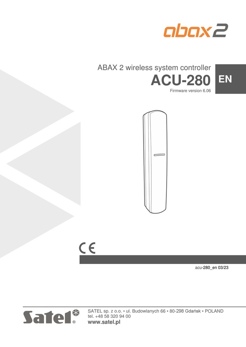
Satel ABAX 2 ACU-280 User manual

ABAX 2 wireless system controller
ACU-280
Firmware version 6.07
acu-280_en 04/23
SATEL sp. z o.o. •ul. Budowlanych 66 • 80-298 Gdańsk • POLAND
tel. +48 58 320 94 00
www.satel.pl
EN

IMPORTANT
The device should be installed by qualified personnel.
Prior to installation, please read carefully this manual in order to avoid mistakes that can lead
to malfunction or even damage to the equipment.
Disconnect power before making any electrical connections.
Changes, modifications or repairs not authorized by the manufacturer shall void your rights
under the warranty.
The rating plate of the device is located on the enclosure base.
The device meets the requirements of the applicable EU directives.
The device is designed for indoor installation.
The device must not be disposed of with other municipal waste. It should be disposed of
in accordance with the existing rules for environment protection (the device was placed
on the market after 13 August 2005).
The device meets the technical regulations of the Eurasian Customs Union.
SATEL aims to continually improve the quality of its products, which may result in changes in
their technical specifications and software. Current information about the changes being
introduced is available on our website.
Please visit us at:
https://support.satel.pl
Hereby, SATEL sp. z o.o. declares that the radio equipment type ACU-280 is in
compliance with Directive 2014/53/EU. The full text of the EU declaration of conformity
is available at the following internet address: www.satel.pl/ce
In the EU, this radio equipment is only permitted to operate in the 868 MHz frequency
band.
The following symbols may be used in this manual:
- note,
- caution.

Changes made to the firmware version 6.07
RS-485 bus
New groups in the table of Modbus RTU protocol registers.

2 ACU-280 SATEL
CONTENTS
1Introduction.......................................................................................................................5
2Features............................................................................................................................5
3Electronics board..............................................................................................................6
3.1 Terminals...................................................................................................................6
3.2DIP-switches..............................................................................................................7
3.2.1 Selecting the controller operating mode.................................................................7
3.2.2 Address setting [controller in the INTEGRA system]..............................................7
3.2.3 Enabling / disabling the support of the unregistered ARF-200 tester.....................8
3.3 RS-485 bus [module of wireless devices with Modbus RTU interface]......................8
3.3.1 Table of Modbus RTU protocol registers ...............................................................8
4Installation of the controller.............................................................................................11
4.1 Selecting a mounting location..................................................................................11
4.2 Preparing the cabling...............................................................................................12
4.3 Installation of enclosure...........................................................................................12
4.4 Setting DIP switches................................................................................................14
4.5 Connecting the wires...............................................................................................14
4.5.1 Expander of wireless devices for SATEL alarm control panels............................14
4.5.2 Module of wireless devices with Modbus RTU interface......................................15
4.6 Powering on and starting the controller ...................................................................16
5ABAX 2 Soft program......................................................................................................16
5.1 Description of the program ......................................................................................16
5.1.1 Menu bar in the program......................................................................................16
5.1.2 Additional menu...................................................................................................17
5.2 Establishing connection between the program and the controller............................17
5.3 Configuration ...........................................................................................................18
5.4 Devices....................................................................................................................19
5.5 Status ......................................................................................................................20
5.5.1 Graphs.................................................................................................................22
5.5.2 Comm. history......................................................................................................23
5.6 Keyfobs....................................................................................................................24
5.6.1 Keyfob state.........................................................................................................25
6Wireless devices supported by the controller..................................................................26
6.1 Devices....................................................................................................................26
6.2 Keypads...................................................................................................................27
6.3 Keyfob .....................................................................................................................27
7Installation of ABAX 2 wireless devices..........................................................................27
7.1 Registering devices to the controller........................................................................27
7.1.1 Expander for the INTEGRA series control panels................................................28
7.1.1.1 Adding new wireless devices........................................................................30
7.1.1.2 Removing wireless devices ..........................................................................32
7.1.2 Expander for the PERFECTA 64 M control panel................................................33
7.1.2.1 Adding new wireless devices........................................................................34
7.1.2.2 Removing wireless devices ..........................................................................36
7.1.3 Expander for VERSA series control panels .........................................................36
7.1.3.1 Adding new wireless devices........................................................................36
7.1.3.2 Removing wireless devices ..........................................................................38
7.1.4 Module of wireless devices with Modbus RTU interface......................................38

SATEL ACU-280 3
7.1.4.1 Adding new wireless devices........................................................................39
7.1.4.2 Removing wireless devices ..........................................................................39
8Programming the ABAX 2 system ..................................................................................40
8.1 Expander for the INTEGRA / VERSA series control panels....................................40
8.1.1 Controller settings................................................................................................40
8.1.2 Functions.............................................................................................................42
8.1.3 Device settings ....................................................................................................42
8.1.3.1 Programming devices using the DLOADX program .....................................44
8.1.3.2 Programming devices using the LCD keypad...............................................48
8.1.4 Specific character of the operation of wireless devices .......................................52
8.1.4.1 Wireless detectors........................................................................................52
8.1.4.2 Wireless sirens.............................................................................................52
8.1.4.3 Wireless expanders of hardwired zones and outputs...................................53
8.1.4.4 Smart plug / Wireless 230 VAC controller ....................................................53
8.1.4.5 Wireless radiator thermostat.........................................................................53
8.1.4.6 Radio signal repeater ...................................................................................54
8.2 Expander for the PERFECTA 64 M control panel....................................................54
8.2.1 Controller settings................................................................................................54
8.2.1.1 Wireless devices...........................................................................................55
8.2.2 Programming devices in the PERFECTA Soft program.......................................56
8.2.3 Specific character of the wireless devices operation ...........................................59
8.2.3.1 Wireless detectors........................................................................................60
8.2.3.2 Wireless sirens.............................................................................................60
8.2.3.3 Wireless expanders of hardwired zones and outputs...................................61
8.2.3.4 Smart plug / 230 VAC wireless controller.....................................................61
8.2.3.5 Wireless radiator thermostat.........................................................................62
8.2.3.6 Radio signal repeater ...................................................................................62
8.3 Module of wireless devices with Modbus RTU interface..........................................62
8.3.1 Programming devices using the ABAX 2 Soft program .......................................62
8.3.2 Specific character of the operation of wireless devices .......................................65
8.3.2.1 Wireless detectors........................................................................................65
8.3.2.2 Wireless sirens.............................................................................................66
8.3.2.3 Wireless expanders of hardwired zones and outputs...................................66
8.3.2.4 Smart plug / Wireless 230 VAC controller ....................................................67
8.3.2.5 Wireless radiator thermostat.........................................................................67
8.3.2.6 Radio signal repeater ...................................................................................67
9APT-200 keyfobs............................................................................................................67
9.1 Expander of wireless devices for SATEL alarm control panels ...............................68
9.1.1 Keyfobs in the INTEGRA system.........................................................................68
9.1.1.1 Keyfob management using the DLOADX program.......................................69
9.1.2 Keyfobs in the PERFECTA 64 M system.............................................................70
9.1.2.1 Keyfob management using the PERFECTA Soft program...........................70
9.1.3 Keyfobs in the VERSA system ............................................................................72
9.1.3.1 Keyfob management using the DLOADX program.......................................72
9.2 Module of wireless devices with Modbus RTU interface..........................................74
9.2.1 Keyfob management............................................................................................74
9.2.1.1 Adding a keyfob............................................................................................74
9.2.1.2 Removing a keyfob.......................................................................................74
10 Controller firmware update .............................................................................................74
10.1 Updating the firmware of ABAX 2 wireless devices.................................................75
11 Restoring the controller factory settings..........................................................................75
4 ACU-280 SATEL
12 Battery replacement in ABAX 2 device...........................................................................75
13 Specifications..................................................................................................................76
14 Manual update history.....................................................................................................77

SATEL ACU-280 5
1 Introduction
The ACU-280 controller enables expansion of the alarm system by adding the ABAX 2
wireless devices. It can work as:
•expander of wireless devices for:
–INTEGRA series control panels (firmware version 1.21 or newer),
–PERFECTA 64 M control panel,
–VERSA series control panels (firmware version 1.09 or newer),
•module of wireless devices with Modbus RTU interface.
The controller does not support the ABAX wireless devices.
The ABAX 2 system offers two-way communication. All transmissions are acknowledged,
which ensures that the information has been received and makes it possible to check the
presence of devices in the system in real time. Configuration of settings, testing and updating
of the firmware of wireless devices are carried out via radio and, consequently, do not require
removal of their enclosure.
2 Features
•Support for up to 48 ABAX 2 wireless devices (the number of supported devices depends
on the configuration).
•Support for ABAX 2 wireless keypads:
–up to 4 INT-KWRL2 keypads,
–up to 4 PRF-LCD-A2 keypads,
–up to 6 VERSA-KWRL2 keypads.
•Support for APT-200 keyfobs (the number of supported keyfobs depends on the
maximum number of control panel users).
•AES standard encrypted two-way radio communication in the 868 MHz / 915 MHz
frequency band.
•Transmission channel diversity –4 channels for automatic selection of the one that will
enable transmission without interference with other signals in the 868 MHz / 915 MHz
frequency band.
•Communication bus for connecting the controller to a SATEL control panel.
•RS-485 communication bus for integrating the controller, e.g. with automation or data
acquisition systems [module of wireless devices with Modbus RTU interface].
•Controller firmware update capability.
•Ability to remotely update the firmware of wireless devices (except for the ASD-250
wireless smoke detector).
•Tamper protection against enclosure opening.

6 ACU-280 SATEL
3 Electronics board
Fig. 1. Controller electronics board.
DIP-switches.
LED indicating the status of communication with the control panel:
ON –no communication with the control panel,
flashing –communication with the control panel OK.
tamper switch.
RS-232 port (TTL standard).
3.1 Terminals
+12V - power input.
COM - common ground.
CKM - keypad bus clock.
DTM - keypad bus data.
CKE - expander bus clock.
DTE - expander bus data.
A RS485 B - RS-485 bus.

SATEL ACU-280 7
3.2 DIP-switches
Using the DIP-switches, you can:
•define the controller operating mode,
•set the controller address (operating mode: expander of wireless devices for the
INTEGRA series control panels),
•enable / disable the support of the ARF-200 radio signal level tester that has not been
registered to the controller.
3.2.1 Selecting the controller operating mode
Fig. 2. Switches defining the controller operating mode.
Switches 9 and 10 (Fig. 2) define the controller operating mode –see Table 1.
Controller operating mode
DIP-switch
9
10
Expander of wireless devices for the INTEGRA series control
panels
OFF
OFF
Expander of wireless devices for the PERFECTA 64 M control
panel
OFF
ON
Expander of wireless devices for the VERSA series control
panels
OFF
ON
Universal module of wireless devices
ON
OFF
ON
ON
Table 1.
3.2.2 Address setting [controller in the INTEGRA system]
Fig. 3. Switches for setting the address of the controller in the INTEGRA system.
Switches 1-5 (Fig. 3) are used to set the address when the controller is connected to the
INTEGRA series control panel (in the other operating modes, the settings of switches 1-5 are
irrelevant). Numerical value is assigned to each switch. In OFF position, the value is 0.

8 ACU-280 SATEL
Numerical values assigned to individual switches in ON position are presented in Table 2.
The sum of numerical values assigned to switches 1-5 constitutes the address set in the
device. The address must be different than that set in the other devices connected to the
expander bus of the control panel.
DIP-switch
1
2
3
4
5
Number
1
2
4
8
16
Table 2.
If the controller is to be connected to the control panel to which an ABAX 2 / ABAX
controller is already connected, it is recommended that the address to be set in the
new controller be higher than that in the controller already connected to the control
panel.
3.2.3 Enabling / disabling the support of the unregistered ARF-200 tester
Fig. 4. Switch for enabling / disabling the support of the unregistered ARF-200 tester.
Switch 7 (Fig. 4) is used to enable / disable the support of the ARF-200 tester that has not
been registered to the controller:
OFF position –support disabled (the controller will support the ARF-200 tester only if it is
registered to the system),
ON position –support enabled.
Remember to disable the support of the unregistered ARF-200 tester after the testing
is finished.
3.3 RS-485 bus [module of wireless devices with Modbus RTU interface]
The RS-485 bus can integrate the controller with other systems (e.g. automation or data
acquisition systems) to inform the systems on the state of wireless devices and to receive
from them control commands for the controller. The data is transmitted using the Modbus
RTU communications protocol. The controller is a “Slave” type device and it supports two
functions of the protocol:
Read Holding Registers (kod: 0x03 [hex], 03 [dec]) –reading values from one or more
registers.
Write Multiple registers (kod: 0x10 [hex], 16 [dec]) –changing values in one or more
registers.
3.3.1 Table of Modbus RTU protocol registers
In table 3 you will find a list of 2-byte memory registers of the controller used for
communication via the Modbus RTU protocol. You can read the value of all the registers
listed in the table using the “Read Holding Registers” function (“R” symbol). Those registers,
whose value can be changed using the “Write Multiple Registers” function, are marked with

SATEL ACU-280 9
a “W” symbol. 48 registers in each group (e.g. 0x0000 – 0x002F) amount to the maximum
number of devices that the controller can support. The first register in the group is assigned
to the first device on the list of devices supported by the controller. The rest of the registers
are assigned accordingly, each to a subsequent device on the list. The group containing
4 registers which convey information on the keyfobs supported by the controller is
an exception. The “Value” column shows values assumed by the registers in each group.
Inside the square brackets you will find names of columns in which those values are
presented in the ABAX 2 Soft program (see “Devices status”).
Group of
registers
Value
R/W
0x0000 –0x002F
(0 –47)
Device status information [State]
Registers can assume values 0x0000 (0) or 0x0001 (1).
Depending on the type of device, registers assume value
0x0001 (1) in the following cases:
•detector: alarm,
•siren: signaling triggered,
•expander of wired zones/outputs: zone activated,
•ASW-200 smart plug: button pressed / relay turned on
(230 VAC power ON),
•ASW-210 controller: input activated / relay turned on
(230 VAC power ON),
•radiator thermostat: radiator valve open (in position other than
fully closed).
R
0x0100 –0x012F
(256 –303)
Tamper information [TMP] / Information about anti-freeze
protection (ART-200 thermostat)
Registers can assume value:
0x0000 (0) –no tamper / anti-freeze protection is not activated,
0x0001 (1) –tamper / anti-freeze protection is activated.
R
0x0200 –0x022F
(512 –559)
Information about radio communication between device and
controller [Comm.] / Information about ART-200 thermostat
error
Registers can assume value:
0x0000 (0) –communication OK / ART-200 thermostat operation
OK,
0x0001 (1) –no communication for the time defined by the
“Communication period” / “ECO” and “Filter”
parameters / ART-200 thermostat error (problem
with changing the valve position [F01] / wrong
calibration [F02] / low battery [F03]).
R
0x0300 –0x032F
(768 –815)
Information about the device power state [Pow.]
Registers can assume value:
0x0000 (0) –power OK,
0x0001 (1) –power trouble (e.g. low battery).
R

10 ACU-280 SATEL
Group of
registers
Value
R/W
0x0400 –0x042F
(1024 –1071)
Detector operating mode [Act.] / / ART-200 thermostat
operating mode
Registers can assume value:
0x0000 (0) –detector works in passive mode / thermostat works
in “Economic temperature” mode,
0x0001 (1) –detector works in active mode / thermostat works in
“Comfortable temperature” mode.
R/W
0x0500 –0x052F
(1280 –1327)
Device control [State]
Registers can assume values 0x0000 (0) or 0x0001 (1).
If register assumes value 0x0001 (1):
•siren: signaling is triggered,
•expander of wired zones/outputs: output is activated,
•ASW-200 smart plug: relay is turned on (connected device is
on),
•ASW-210 controller: relay is turned on (power is on).
R/W
0x0600 –0x062F
(1536 –1583)
Temperature registered by the temperature sensor in the
device [Temperature]
Temperature is registered in the range of -10°C to +50°C with
0.5° accuracy. Registers can assume integer values preceded by
a sign. For the purpose of conversion, registered temperatures
are multiplied by 10, e.g. for temperature +23.5°C the register
assumes value +235.
R
0x0700 –0x072F
(1792 –1839)
Level of the radio signal received from the device by the
controller [RSSI ACU]
Level of signal is registered in %. Registers can assume values
from 0 to 100.
R
0x0800 –0x082F
(2048 –2095)
Level of the radio signal received by the device from the
controller [RSSI dev.]
Level of signal is registered in %. Registers can assume values
from 0 to 100.
R
0x0900 –0x092F
(2304 –2351)
Value of the supply voltage [Pow. volt.]
Value of voltage supplied to devices supported by the controller
is registered in mV, e.g. for voltage of 3.06 V the register
assumes value 3060.
R
0x0A00 –0x0A03
(2560 –2563)
Information about active keyfob
Read values from 4 registers:
0x0A00 –keyfob number in the controller (1 –256),
0x0A01 –number of transmissions received from the keyfob by
the controller,
0x0A02 –number of pressed button (0 –5),
0x0A03 –battery status (0 –battery OK; 1 –low battery).
The above-mentioned registers assume values greater than 0
only when the controller receives a transmission from the keyfob.
R

SATEL ACU-280 11
Group of
registers
Value
R/W
0x0B00 –0x0B2F
(2816 –2863)
ASW-200 smart plug supply voltage
Value of voltage supplied to ASW-200 plugs supported by the
controller. Registered values of AC voltage are multiplied by 10,
e.g. for voltage of 229.5 VAC the register assumes value 2295.
R
0x0C00 –0x0C2F
(3072 –3119)
Current consumption by device connected to ASW-200
smart plug
Value of current consumed by devices connected to ASW-200
plugs. Registered values are multiplied by 100, e.g. for current of
7.15 A the register assumes value 715.
R
0x0E00 –0x0E2F
(3584 –3631)
Economy temperature (ART-200 thermostat)
Temperature is read / registered in the range of 5°C to +35°C
with 0.5° accuracy. Registers can assume integer values
preceded by a sign. For the purpose of conversion, registered
temperatures are multiplied by 10, e.g. for temperature +23.5°C
the register assumes value +235.
R/W
0x0F00 –0x0F2F
(3840 –3887)
Comfort temperature (ATR-200 thermostat)
Temperature is read / registered in the range of 5°C to +35°C
with 0.5° accuracy. Registers can assume integer values
preceded by a sign. For the purpose of conversion, registered
temperatures are multiplied by 10, e.g. for temperature +23.5°C
the register assumes value +235.
R/W
0x1000 –0x102F
(4096 –4143)
ART-200 thermostat control using the Modbus RTU protocol
Registers can assume values:
0x0000 (0) –control using the Modbus RTU protocol disabled.
The thermostat operates according to the selected
mode.
0x0001 (1) –control using the Modbus RTU protocol enabled.
The thermostat operating modes are not used.
The thermostat keys are disabled.
R/W
0x1100 –0x112F
(4352 –4399)
Radiator valve position (ART-200 thermostat)
Radiator valve position is read / set in the range of 0% to 100%.
R/W
Table 3.
4 Installation of the controller
Disconnect power before making any electrical connections.
Be careful during installation to avoid damage to the components located on the
controller electronics board.
4.1 Selecting a mounting location
The controller should be installed indoors, in spaces with normal air humidity. Prior to
installation you should plan the arrangement of all ABAX 2 wireless devices which are to be
operated by the controller. Select the installation place so that these devices are located
within the controller operating range. Remember that thick walls, metal partitions, etc. will

12 ACU-280 SATEL
reduce the range of the radio signal. It is recommended that the controller be mounted high
above the floor. This will allow you to get a better range of radio communication and avoid
the risk of the controller being accidentally covered by people moving around the premises.
Installing the device in close vicinity of electrical systems is not recommended, since it can
adversely affect the range of radio signal.
Several ABAX 2 / ABAX wireless system controllers can work within each other's range.
The number of wireless devices working within each other's operating range depends on the
frequency of periodical communication. The higher the frequency of communication,
the lesser number of devices can work within each other's range.
4.2 Preparing the cabling
Run the cables to be used to connect the controller to the control panel or other devices to
the controller's installation location. For power cables, use flexible conductors with cross-
sectional area of 0.5-0.75 mm2. In order to connect the controller to the RS-485
communication bus, use the twisted-pair type of cable (e.g. UTP –unshielded twisted pair).
Do not lay the cables in immediate vicinity of the low-voltage electrical network wires,
especially those used for powering the high-power equipment (such as electric motors).
4.3 Installation of enclosure
The description below applies to the enclosure in which the ACU-280 controller is sold.
1. Open the controller enclosure (Fig. 5). The enclosure opening tool, shown in the
illustration, is included in the detector delivery set.
2. Place the enclosure base against the wall and mark location of the mounting holes.
Set the enclosure so that the cable entry opening is situated at the bottom of the
enclosure or at the base.
3. Drill holes for wall plugs (anchors) in the wall.
4. Make the cable entry opening at the base. The opening diameter must be larger than
5 mm. The finished opening must not have sharp edges.
5. Run the cables through the prepared opening (power cables, cables connecting the
controller with the control panel or other devices, etc.).
6. Using wall plugs and screws, secure the enclosure base to the wall. The wall plugs
delivered with the device are intended for concrete, brick, etc. For other types of surface
(drywall, styrofoam), use the appropriately selected wall plugs. When installed, the device
must withstand a pull-off force of at least 50 N.

SATEL ACU-280 13
Fig. 5. Opening the enclosure.
Fig. 6. Installation of enclosure base.

14 ACU-280 SATEL
4.4 Setting DIP switches
Using the DIP switches (see “DIP-switches” p. 7):
1. Define the controller operating mode (switches 9 and 10).
2. Set the controller's address if the controller is to be connected to the INTEGRA series
control panel (switches 1-5).
4.5 Connecting the wires
Protect the wiring against contact with sharp edges or else they can damage the
insulation of cables.
4.5.1 Expander of wireless devices for SATEL alarm control panels
Depending on the alarm system in which the controller is to operate:
INTEGRA: connect the CKM, DTM, CKE, DTE and COM terminals to the corresponding
terminals of the control panel communication buses (Fig. 7).
Fig. 7. Method of connecting the controller to the INTEGRA series control panel.
VERSA: connect the CKE, DTE and COM terminals to the corresponding terminals of the
control panel communication bus (Fig. 8).
Fig. 8. Method of connecting the controller to the VERSA series control panels.
PERFECTA 64 M: connect the CKE, DTE and COM terminals to the corresponding terminals
of the control panel communication bus (Fig. 9).
You can connect only one ABAX 2 controller to the PERFECTA 64 M control panel.

SATEL ACU-280 15
If the ACU-220 controller is connected to the PERFECTA 64 M control panel, do not
connect the PERFECTA-RF module or the INT-RX-S expander to the control panel.
The PERFECTA 64 M control panel can support only one of these devices.
Fig. 9. Method of connecting the controller to the PERFECTA 64 M control panel.
If you use the twisted-pair type of cable, remember that the DTM and CKM / CKE and DTE
(clock and data) signals must not be sent through one pair of twisted conductors.
The conductors must be run in one cable.
4.5.2 Module of wireless devices with Modbus RTU interface
For connecting the RS-485 bus, connect the A and B terminals with the corresponding lines
of the bus, as shown in figure 10. 100 Ω(
±
10%) resistors should be installed at the
beginning and at the end of the bus. Connect the COM terminals of all devices connected to
the bus with an additional wire. The maximum number of “Slave” type devices
(e.g. ACU-280) that can be connected to the bus is n = 247.
Fig. 10. Method of connecting the controller to the RS-485 bus (RT= 100 Ω (
±
10%);
n = 247).

16 ACU-280 SATEL
4.6 Powering on and starting the controller
1. Connect the power cables to the +12V and COM terminals. The controller may be
powered directly from the control panel or from a power supply with current limitation up
to 3 A.
2. Replace the cover.
3. Turn the power on. The LED indicator should come on.
If the controller works as expander of wireless devices for SATEL alarm control
panels, run the identification function in the control panel (see the control panel
installer manual). The controller will be identified as ACU-100.
5 ABAX 2 Soft program
The ABAX 2 Soft program enables configuration and diagnostics of the wireless system
when the controller works as module of wireless devices with Modbus RTU interface.
The program can also be used for diagnostics of the system, when the controller works as
expander for a SATEL control panel.
You can download the ABAX 2 Soft program from www.satel.pl website.
Required program version: 1.03.007 (or newer).
5.1 Description of the program
5.1.1 Menu bar in the program
The menu bar is displayed in the top part of the program window.
Fig. 11. ABAX 2 Soft program: menu bar.
type of controller and firmware version.
number of the computer port used for communication with the RS-232 (TTL) port of the
controller.
When the ABAX 2 system is running in the test mode, the “TEST MODE” information is
displayed on the menu bar (after the firmware version).
Buttons
click to establish connection to the controller. The button is displayed when the
program is not connected to the controller.
click to finish connection to the controller. The button is displayed when the program
is connected to the controller.
click to read data from the controller.
click to write data to the controller.
click to display additional menu.

SATEL ACU-280 17
5.1.2 Additional menu
The additional menu is displayed after you click .
Open –click to open the controller data file.
Save –click to write the controller data to file.
Configuration –click to open the “Connection” window.
Language –click to open the “Software language” window.
About –click to display information about the program.
“Connection” window
Fig. 12. ABAX 2 Soft program: “Connection” window.
Port RS-232 –computer COM port to be used for communication with the RS-232 (TTL) port
of the controller.
OK –click to confirm the changes.
Cancel –click to close window without saving changes.
“Software language” window
Fig. 13. ABAX 2 Soft program: “Software language” window.
Software language –you can select the language of the program.
Save –click to confirm the changes.
Cancel –click to close window without saving changes.
5.2 Establishing connection between the program and the controller
1. Connect the controller RS-232 (TTL) port with the computer port using the USB-RS
converter offered by SATEL.
2. Select the computer COM port to be used for communication with the controller
(see ““Connection” window” p. 17).
3. Click on the menu bar.

18 ACU-280 SATEL
4. After connection is established, information about the controller type and firmware version
as well as the button will be displayed on the program menu bar.
5.3 Configuration
Controller info
Module type –controller type.
Version –firmware version of the controller.
Serial number –serial number of the controller.
Communication period –define the time intervals at which wireless devices are to
communicate with the controller. Periodical communication can take place every 12, 24 or
36 seconds. During periodical communication, the devices inform the controller about their
status, and the controller sends commands to the devices (switches the detectors into
active/passive mode, starts/ends test mode, changes configuration of the devices, etc.).
The communication period has effect on the level of energy consumption by wireless
devices: the less frequent is the communication, the lower is the energy consumption.
For the battery-operated devices it means longer battery life. Moreover, when the
communication takes place less frequently, more wireless devices can work within each
other's operating range.
If you enable the “ECO” option for a wireless device, periodical communication
between that device and the controller will take place every 3 minutes
(the “Communication period” parameter will have no effect on the device operation).
Some information and commands need to be sent immediately. Therefore, additional
communication takes place when the device reports tamper, when the detector reports
alarm, etc.
Fig. 14. ABAX 2 Soft program: “Configuration” tab.
Other manuals for ABAX 2 ACU-280
1
Table of contents
Other Satel Controllers manuals

Satel
Satel KNX-BSA12H User manual

Satel
Satel ACU-220 User manual

Satel
Satel ACU-250 User guide

Satel
Satel MICRA VERSA-MCU User manual

Satel
Satel KNX-SA41 User manual

Satel
Satel KNX-SA41 User manual

Satel
Satel KNX-BSA12L User manual

Satel
Satel ACU-270 User manual

Satel
Satel ASW-210 User manual

Satel
Satel ACU-280 User manual

Satel
Satel INT-CR User manual

Satel
Satel RX-2K User manual

Satel
Satel KNX-DIM21 User manual

Satel
Satel KNX-DIM21 User manual

Satel
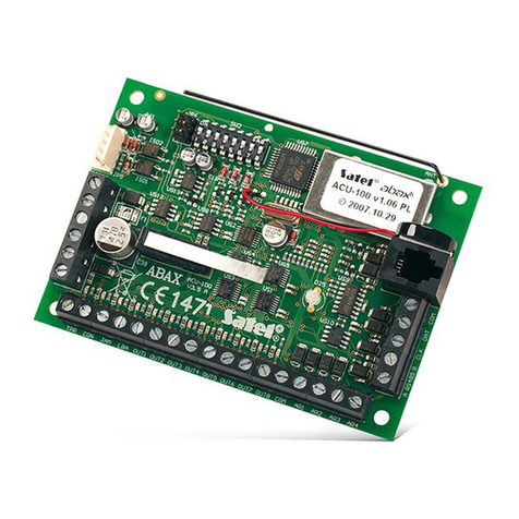
Satel Abax ACU-100 User manual

Satel
Satel ABAX 2 ACU-220 User manual

Satel
Satel ABAX 2 ACU-280 User manual

Satel
Satel MICRA VERSA-MCU User manual

Satel
Satel RX-2K User manual

Satel
Satel VERSA-MCU User manual