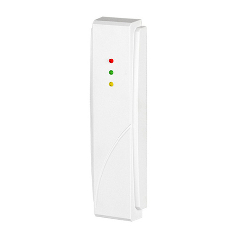
ASW-100 E / ASW-100 F ABAX
2
mode 1 -the button enables the electric circuit to be manually controlled – press the
button to close/open the 230V electric circuit (switch ON/OFF the device
connected to the controller socket).
mode 2 -the button enables the electric circuit to be manually controlled and the
remote control to be disabled – shortly press the button to close/open the
230V electric circuit (switch ON/OFF the device connected to the controller
socket). Press and hold down the button for 3 seconds to disable/enable the
remote control of the electric circuit (with remote control disabled, the LED
indicator is blinking).
The two-color LED provides the following information:
−steady green light – the 230V electric circuit is open (the device connected to the
controller socket is OFF)
−steady red light – the 230V electric circuit is closed (the device connected to the
controller socket is ON)
−blinking green light – remote control of the device is disabled, the 230V electric
circuit is open (the device connected to the controller socket is OFF)
−blinking red light – remote control of the device is disabled, the 230V electric circuit
is closed (the device connected to the controller socket is ON)
In addition, the LED will change its color momentarily during the polling: if
lighting/blinking green, it will give a red flash; if lighting/blinking red, it will give a green
flash.
2. Description of the installation
The ASW-100 E and ASW-100 F 230V wireless controllers should be installed
indoors, in spaces with normal air humidity.
Before plugging the wireless controller into the 230V socket, familiarize
yourself thoroughly with the electrical system in the premises. The phase
conductor in the socket the controller is to be plugged in should be on the
left-hand side, and the neutral conductor – on the right-hand side.
To install the ASW-100 E or ASW-100 F controller in the ABAX system, proceed as
follows:
1. Add the controller to the wireless system (refer to the ACU-100 controller user
manual). Placed on the housing is a sticker with the 7-digit serial number which is
to be entered when registering the controller in the system.
2. Plug the controller into the selected 230V socket.
3. Check the level of signal received by the controller from the controller. If
necessary, select another socket and re-check the signal level.
4. Having selected the installation place which ensures the optimum signal level,
configure the controller as required. Refer to the ACU-100 user manual for
configuration related information.
3. Technical data
Working frequency band.............................................................868.0MHz ÷ 868.6MHz
Range.....................................................................................up to 150m (in open area)
