manuals.online logo
Brands
  1. Home
  2. •
  3. Brands
  4. •
  5. Sauder
  6. •
  7. Indoor Furnishing
  8. •
  9. Sauder 420203 User manual

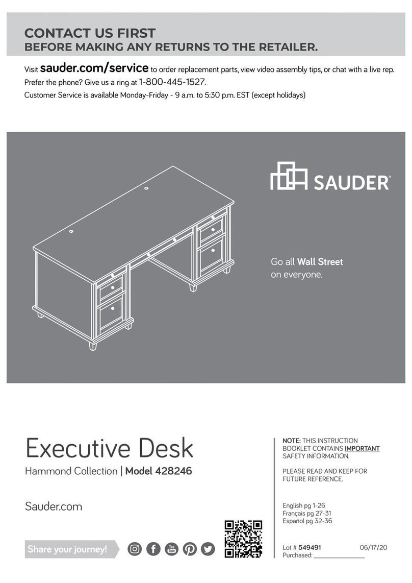
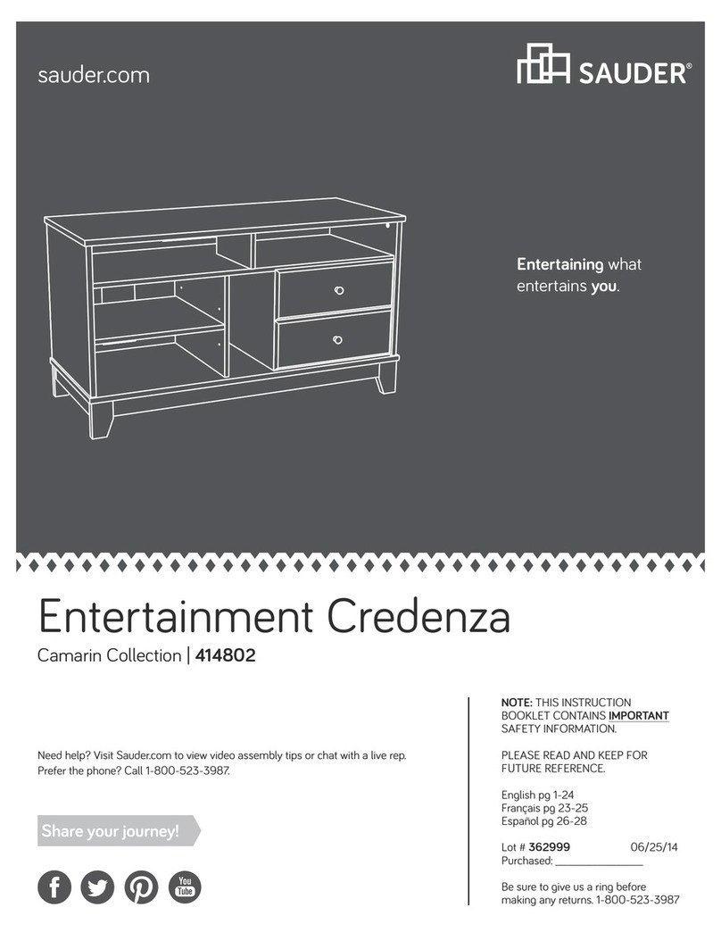
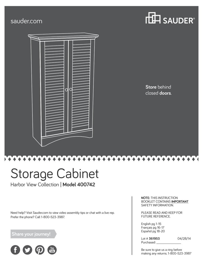
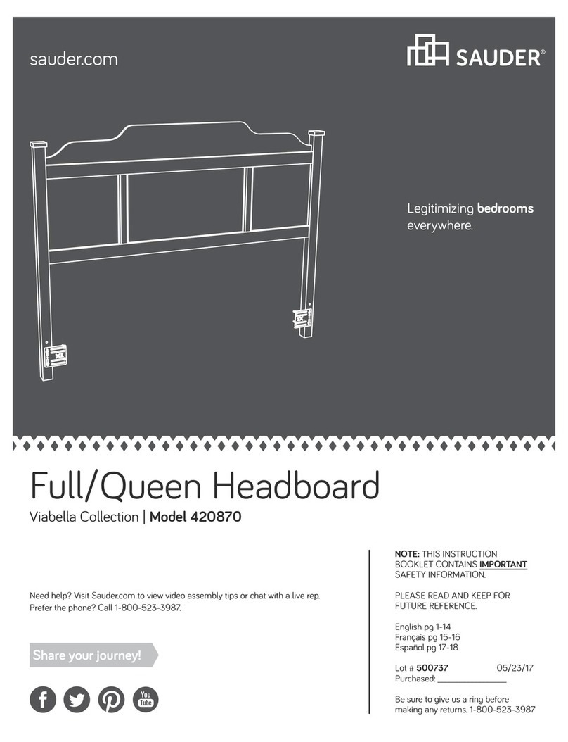
Sauder 420203 User manual

sauder.com
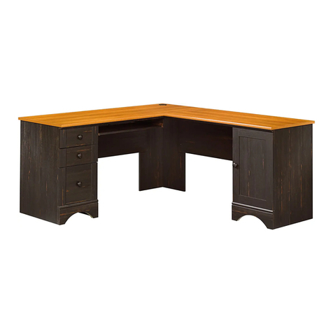
Desk
Model 420203
NOTE: THIS INSTRUCTION
BOOKLET CONTAINS IMPORTANT
SAFETY INFORMATION.
PLEASE READ AND KEEP FOR
FUTURE REFERENCE.
English pg 1-28
Français pg 29-32
Español pg 33-36
Lot # 531643 07/16/19
Purchased: __________________
sauder.com
CONTACT US FIRST
BEFORE MAKING ANY RETURNS TO THE STORE.
Share your journey!
sauder.com
CONTACT US FIRST
BEFORE MAKING ANY RETURNS TO THE STORE.
Visit sauder.com/service to order replacement parts, view video assembly tips, or chat with a live rep.
Prefer the phone? Give us a ring at 1-800-445-1527.
Customer Service is available Monday-Friday - 9 a.m. to 5:30 p.m. EST (except holidays)
Sit and surf.
Table of Contents Assembly Tools Required
3
4
5-28
29-32
33-36
37-38
39
Part Identification
Hardware Identification
Assembly Steps
Français
Español
Safety
Warranty
No. 2 Phillips Screwdriver
Tip Shown Actual Size
Skip the power trip.
This time.
Page 2 www.sauder.com 420203
Part Identification
åWhile not all parts are labeled, some of the parts will have a label or an inked letter on the edge
to help distinguish similar parts from each other. Use this part identification to help identify similar parts.
A RIGHT LEG (1)
B LEFT LEG (1)
C CENTER LEG (1)
D TOP (1)
E RIGHT END (1)
F CENTER END (1)
G CENTER UPRIGHT (1)
H LEFT UPRIGHT (1)
I BACK (1)
J LARGE BACK (1)
K SHELF (1)
L LARGE EXTENSION BLOCK (2)
M SMALL EXTENSION BLOCK (2)
N BRACE (1)
O LONG BRACE (2)
P SHORT BRACE (2)
Q LARGE RIGHT DRAWER SIDE (1)
R LARGE LEFT DRAWER SIDE (1)
S LARGE DRAWER BACK (1)
T LARGE DRAWER BOTTOM (1)
U RIGHT DRAWER SIDE (1)
V LEFT DRAWER SIDE (1)
W DRAWER BACK (1)
X DRAWER BOTTOM (1)
Y DRAWER BRACE (1)
Z DRAWER FRONT (1)
AA LARGE DRAWER FRONT (1)
Now you know
our ABCs.
Page 3www.sauder.com420203
A
B
C
DE
F
G
H
I
J
K
L
M
N
O
P
Q
R
S
T
U
V
W
X
Y
Z
AA
O
M
L
P
Hardware Identification
åScrews are shown actual size. You may receive extra hardware with your unit.
BLACK 1-3/4" PAN HEAD SCREW - 10
13 BLACK 1" PAN HEAD SCREW - 4
14
BLACK 1" FLAT HEAD SCREW - 8
15
BLACK 1/2" MACHINE SCREW - 4
17
BLACK 1/2" FLAT HEAD SCREW - 12
19
BLACK 5/16" MACHINE SCREW - 1
21
BLACK 11/16" FLAT HEAD SCREW - 4
16
BLACK 1/2" PAN HEAD SCREW - 22
18
BLACK 1/2" MACHINE SCREW - 4
20
NUT - 1
11
WOOD DOWEL - 4
8
METAL BRACKET - 6
9PULL - 2
10 TOOL - 1
12
Page 4 www.sauder.com 420203
HIDDEN CAM - 12
5SMALL HIDDEN
CAM - 12
6CAM SCREW - 24
7
4EXTENSION SLIDE - 2
3EXTENSION RAIL - 2
(EXTENSION SET SHOWN SEPARATED)
1LEFT RAIL - 1 2RIGHT RAIL - 1
Step 1 Look for this icon. It means a
video assembly tip is available at
www.sauder.com/services/tips
å Assemble your unit on a carpeted floor or on the empty
carton to avoid scratching your unit or the floor.
å Fasten the LEFT LEG (B) to the LEFT UPRIGHT (H). Use
two BLACK 1-3/4" PAN HEAD SCREWS (13) and two
BLACK 1/2" PAN HEAD SCREWS (18).
Page 5www.sauder.com420203
BLACK 1/2" PAN HEAD SCREW
(2 used in this step)
18
Edge with holes
Surface with holes
BLACK 1-3/4" PAN HEAD SCREW
(2 used in this step)
13
B
H
Step 2
å Fasten the LEFT RAIL (1) and one of the SMALL
EXTENSION BLOCKS (M) to the LEFT UPRIGHT (H)
exactly as shown. Use two BLACK 11/16" FLAT
HEAD SCREWS (16).
å NOTE: Find the back hole first. Then, slide the inner
cartridge of the LEFT RAIL in to find the other hole that
lines up with the hole in the SMALL EXTENSION BLOCK
and LEFT UPRIGHT. Turn a SCREW into this hole.
Page 6 www.sauder.com 420203
BLACK 11/16" FLAT HEAD SCREW
(2 used in this step)
16
H
M
1
These edges
should be even.
This hole is closer
to this edge.
Line up the
back hole first.
Finished surface
1
å Fasten four METAL BRACKETS (9) to the CENTER
LEG (C) exactly as shown. Use four BLACK 1/2" PAN
HEAD SCREWS (18).
Step 3
Page 7www.sauder.com420203
BLACK 1/2" PAN HEAD SCREW
(4 used in this step)
18
C
9
Step 4
å Fasten the CENTER LEG (C) to the CENTER END (F) and
CENTER UPRIGHT (G). Use four BLACK 1/2" PAN HEAD
SCREWS (18) through the METAL BRACKETS on the CENTER
LEG and into the CENTER END and CENTER UPRIGHT.
å Finish fastening the CENTER LEG (C) to the CENTER END (F)
and CENTER UPRIGHT (G). Use four BLACK 1-3/4" PAN
HEAD SCREWS (13).
å Turn two CAM SCREWS (7) into the CENTER END (F).
Page 8 www.sauder.com 420203
BLACK 1/2" PAN HEAD SCREW
(4 used in this step)
18
BLACK 1-3/4" PAN HEAD SCREW
(4 used in this step)
13
G
C
F
Surface with holes
Surface with
fewer holes
Edge without holes
7
å Fasten one of the LARGE EXTENSION BLOCKS (L) to the
CENTER END (F). Use two BLACK 1" PAN HEAD SCREWS (14)
in the outer holes.
Step 5
Page 9www.sauder.com420203
F
L
C
Surface with
more holes
This hole is closer
to this edge.
BLACK 1" PAN HEAD SCREW
(2 used in this step)
14
Step 6
å Carefully flip the CENTER LEG (C) over.
å Fasten the RIGHT RAIL (2) and the remaining SMALL
EXTENSION BLOCK (M) to the CENTER UPRIGHT (G) exactly
as shown. Use two BLACK 11/16" FLAT HEAD SCREWS (16).
å NOTE: Find the back hole first. Then, slide the inner cartridge
of the RIGHT RAIL in to find the other hole that lines up with
the hole in the SMALL EXTENSION BLOCK and CENTER
UPRIGHT. Turn a SCREW into this hole.
Page 10 www.sauder.com 420203
C
BLACK 11/16" FLAT HEAD SCREW
(2 used in this step)
16
M
These edges
should be even.
This hole is closer
to this edge.
Line up the
back hole first.
Finished surface
2
G
2
Step 7
Page 11www.sauder.com420203
å Fasten two METAL BRACKETS (9) to the RIGHT
LEG (A) exactly as shown. Use two BLACK 1/2" PAN
HEAD SCREWS (18).
BLACK 1/2" PAN HEAD SCREW
(2 used in this step)
18
A
9
Step 8
å Fasten the RIGHT LEG (A) to the RIGHT END (E). Use two
BLACK 1/2" PAN HEAD SCREWS (18) through the METAL
BRACKETS on the RIGHT LEG and into the RIGHT END.
å Finish fastening the RIGHT LEG (A) to the RIGHT END (E).
Use two BLACK 1-3/4" PAN HEAD SCREWS (13).
Page 12 www.sauder.com 420203
A
BLACK 1/2" PAN HEAD SCREW
(2 used in this step)
18
BLACK 1-3/4" PAN HEAD SCREW
(2 used in this step)
13
E
Surface
with
holes
Edge without holes
å Fasten the remaining LARGE EXTENSION BLOCK (L)
to the RIGHT END (E). Use two BLACK 1" PAN HEAD
SCREWS (14) in the outer holes.
Step 9
Page 13www.sauder.com420203
Surface with
more holes
This hole is closer
to this edge.
BLACK 1" PAN HEAD SCREW
(2 used in this step)
14
E
A
L
Step 10
å Separate the EXTENSION SLIDES (4) from the EXTENSION RAILS (3) as
shown in the enlarged diagram below. Be prepared, the parts are greasy.
å Fasten the EXTENSION RAILS (3) to the LARGE EXTENSION BLOCKS (L).
Use four BLACK 1/2" FLAT HEAD SCREWS (19).
å NOTE: For each EXTENSION RAIL, turn a SCREW into the back hole. Then,
slide the inner cartridge of the EXTENSION RAIL in to find the other hole that
lines up with the hole in the LARGE EXTENSION BLOCK. Turn a SCREW into
this hole.
å NOTE: The EXTENSION SLIDES will be used later for the LARGE DRAWER.
Page 14 www.sauder.com 420203
Push on the black lever and pull the SLIDE from the RAIL.
A
C
L
L
4
3
3
3
3
BLACK 1/2" FLAT HEAD SCREW
(4 used in this step)
19
G
Use these holes.
Open end
Open end
Open end
Back hole
Back hole
å Separate the BLACK 1/2" MACHINE SCREWS (17 and 20). Use
the thicker SCREW (20) in this step.
å Turn two CAM SCREWS (7) into the RIGHT END (E).
å Insert two SMALL HIDDEN CAMS (6) into the LARGE BACK (J).
å Fasten the LARGE BACK (J) to the RIGHT END (E). Tighten two
HIDDEN CAMS.
å Fasten the SHORT BRACES (P) to the RIGHT LEG (A). Use two
BLACK 1/2" MACHINE SCREWS (20).
Step 11
Page 15www.sauder.com420203
7
E
J
A
P
3
21
6
The arrow must
point toward the
edge of the board.
6
BLACK 1/2" MACHINE SCREW
(2 used for the SHORT BRACES)
20
These edges
should be even.
These edges
should be even.
Surface
with holes
Surface without holes
P
Step 12
å Insert two SMALL HIDDEN CAMS (6) into the LARGE BACK (J).
å Fasten the CENTER END (F) the LARGE BACK (J). Tighten two
HIDDEN CAMS.
å Fasten the CENTER LEG (C) to the SHORT BRACES (P). Use
two BLACK 1/2" MACHINE SCREWS (20).
Page 16 www.sauder.com 420203
3
21
6
The arrow must
point toward the
edge of the board.
J
P
6
BLACK 1/2" MACHINE SCREW
(2 used for the SHORT BRACES)
20
P
C
F
å Carefully stand your unit upright.
å Turn four CAM SCREWS (7) into the SHELF (K).
å Insert four HIDDEN CAMS (5) into the ENDS (E and F).
å Fasten the SHELF (K) to the ENDS (E and F). Tighten four
HIDDEN CAMS.
Step 13
Page 17www.sauder.com420203
3
21
5
The arrow must
point toward the
edge of the board.
E
F
K
K
Surface
with holes
5
5
7
Step 14
å Turn two CAM SCREWS (7) into the LEFT UPRIGHT (H).
å Insert two HIDDEN CAMS (5) into the BACK (I).
å Fasten the BACK (I) to the LEFT UPRIGHT (H). Tighten
two HIDDEN CAMS.
å Fasten the BRACE (N) to the LEFT LEG (B). Use two
BLACK 1/2" PAN HEAD SCREWS (18).
Page 18 www.sauder.com 420203
3
21
5
The arrow must
point toward the
edge of the board.
N
B
I
H
N
BLACK 1/2" PAN HEAD SCREW
(2 used for the BRACE)
18
5
7
Finished edge
Surface with holes
å Carefully stand the LEFT LEG (B) upright.
å Turn two CAM SCREWS (7) into the CENTER UPRIGHT (G).
å Insert two HIDDEN CAMS (5) into the BACK (I).
å Fasten the BACK (I) to the CENTER UPRIGHT (G). Tighten
two HIDDEN CAMS.
å Fasten the BRACE (N) to the CENTER LEG (C). Use two
BLACK 1/2" PAN HEAD SCREWS (18).
Step 15
Page 19www.sauder.com420203
BLACK 1/2" PAN HEAD SCREW
(2 used for the BRACE)
18
3
21
5
The arrow must
point toward the
edge of the board.
5
7
N
I
C
G
B
Step 16
å Turn four CAM SCREWS (7) into the TOP (D).
å Insert four HIDDEN CAMS (5) into the UPRIGHTS (G and H).
å Fasten the TOP (D) to the UPRIGHTS (G and H). Tighten four
HIDDEN CAMS.
å Fasten the TOP (D) to the RIGHT LEG (A). Use two BLACK
1-3/4" PAN HEAD SCREWS (13).
Page 20 www.sauder.com 420203
3
21
5
The arrow must
point toward the
edge of the board.
Surface
with holes
H
G
D
A
BLACK 1-3/4" PAN HEAD SCREW
(2 used for the RIGHT LEG)
13
D
7
7
5

Other Sauder Indoor Furnishing manuals

Sauder Hammond 431249 User manual

Sauder

Sauder Hammond 431249 User manual

Sauder 416519 User manual

Sauder

Sauder 416519 User manual

Sauder Barrister Lane Storage Credenza 414721 User manual

Sauder

Sauder Barrister Lane Storage Credenza 414721 User manual

Sauder Edge Water 419401 User manual

Sauder

Sauder Edge Water 419401 User manual

Sauder Worksense MASON PEAK 427835 User manual

Sauder

Sauder Worksense MASON PEAK 427835 User manual

Sauder 423493 User manual

Sauder

Sauder 423493 User manual

Sauder 420566 User manual

Sauder

Sauder 420566 User manual

Sauder 423742 User manual

Sauder

Sauder 423742 User manual

Sauder 2-Door Wardrobe/Armoire Clothes Storage Cabinet With Hanger Rod & Shelves... User manual

Sauder

Sauder 2-Door Wardrobe/Armoire Clothes Storage Cabinet With Hanger Rod & Shelves... User manual

Sauder Via 419609 User manual

Sauder

Sauder Via 419609 User manual

Sauder Heritage Collection User manual

Sauder

Sauder Heritage Collection User manual

Sauder Office Works Affirm 427450 User manual

Sauder

Sauder Office Works Affirm 427450 User manual

Sauder New Grange 419128 User manual

Sauder

Sauder New Grange 419128 User manual

Sauder 418073 User manual

Sauder

Sauder 418073 User manual

Sauder Carson Forge 420422 User manual

Sauder

Sauder Carson Forge 420422 User manual

Sauder Storage Cabinet 419496 User manual

Sauder

Sauder Storage Cabinet 419496 User manual

Sauder 403785 User manual

Sauder

Sauder 403785 User manual

Sauder 408726 User manual

Sauder

Sauder 408726 User manual

Sauder Harbor View 158002 User manual

Sauder

Sauder Harbor View 158002 User manual

Sauder Dakota Pass 418268 User manual

Sauder

Sauder Dakota Pass 418268 User manual

Sauder Shoal Creek 411203 User manual

Sauder

Sauder Shoal Creek 411203 User manual

Sauder Edge Water Series User manual

Sauder

Sauder Edge Water Series User manual

Sauder Cannery Bridge 426140 User manual

Sauder

Sauder Cannery Bridge 426140 User manual

Sauder 109872 User manual

Sauder

Sauder 109872 User manual

Popular Indoor Furnishing manuals by other brands

John Lewis GARMENT RAIL user guide

John Lewis

John Lewis GARMENT RAIL user guide

velda 4i instructions

velda

velda 4i instructions

Donco 750 TENT BED Assembly instructions

Donco

Donco 750 TENT BED Assembly instructions

Whittier Wood 1200AFVCL Assembly instructions

Whittier Wood

Whittier Wood 1200AFVCL Assembly instructions

RiverRidge Somerset 06-039 Assembly instructions

RiverRidge

RiverRidge Somerset 06-039 Assembly instructions

Ilva IDPI-16090 Assembly instruction

Ilva

Ilva IDPI-16090 Assembly instruction

World Market 551917 Assembly instructions

World Market

World Market 551917 Assembly instructions

Hillsdale Furniture Bayview 103720-111032 Assembly instructions

Hillsdale Furniture

Hillsdale Furniture Bayview 103720-111032 Assembly instructions

Uplift Desk E7 Electric instructions

Uplift Desk

Uplift Desk E7 Electric instructions

Dorel Asia PARSONS CHAIR DA6090-PL Assembly instructions

Dorel Asia

Dorel Asia PARSONS CHAIR DA6090-PL Assembly instructions

Safavieh Furniture Lucas AMH6501A quick start guide

Safavieh Furniture

Safavieh Furniture Lucas AMH6501A quick start guide

Teulat Totem Cabinet 2D 17309 TE Assembly instructions

Teulat

Teulat Totem Cabinet 2D 17309 TE Assembly instructions

Emmezeta 102017 Assembling instructions

Emmezeta

Emmezeta 102017 Assembling instructions

Dorel Living DL7891G-1 manual

Dorel Living

Dorel Living DL7891G-1 manual

Seconique BROOKLYN Assembly instructions

Seconique

Seconique BROOKLYN Assembly instructions

Walker Edison AF32ALGD Assembly instructions

Walker Edison

Walker Edison AF32ALGD Assembly instructions

UBERHAUS DESIGN 79345030 Operator's manual

UBERHAUS DESIGN

UBERHAUS DESIGN 79345030 Operator's manual

Bolia ROD 10 Assembly manual

Bolia

Bolia ROD 10 Assembly manual

manuals.online logo
manuals.online logoBrands
  • About & Mission
  • Contact us
  • Privacy Policy
  • Terms and Conditions

Copyright 2025 Manuals.Online. All Rights Reserved.