manuals.online logo
Brands
  1. Home
  2. •
  3. Brands
  4. •
  5. Sauder
  6. •
  7. Indoor Furnishing
  8. •
  9. Sauder Cannery Bridge 420374 User manual

Sauder Cannery Bridge 420374 User manual

Need help? Visit Sauder.com to view video assembly tips or chat with a live rep.
Prefer the phone? Call 1-800-523-3987.
Share your journey!
sauder.com
It's addicting.
NOTE: THIS INSTRUCTION
BOOKLET CONTAINS IMPORTANT
SAFETY INFORMATION.
PLEASE READ AND KEEP FOR
FUTURE REFERENCE.
English pg 1-15
Français pg 16-18
Español pg 19-21
Lot # 389961 04/22/16
Purchased: __________________
Be sure to give us a ring before
making any returns. 1-800-523-3987
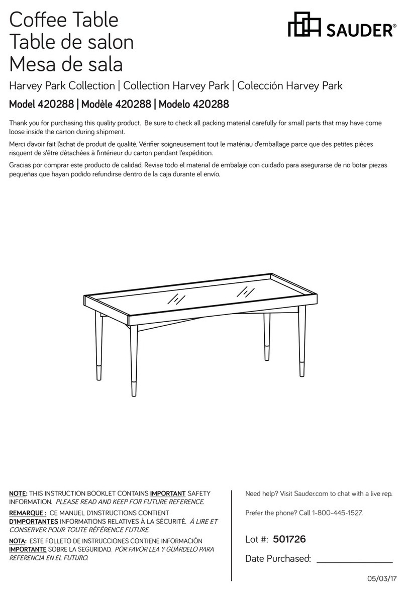
Crate Coee Table
Cannery Bridge Collection | Model 420374
Table of Contents Assembly Tools Required
Part Identification
Hardware Identification
Assembly Steps
Français
Español
Safety
Warranty
Hammer
Not actual size
No. 2 Phillips Screwdriver
Tip Shown Actual Size
Skip the power trip.
This time.
3
4
5-15
16-18
19-21
22
23
420374 www.sauder.com/servicesPage 2
åWhile not all parts are labeled, some of the parts will have a label or an inked letter on the edge
to help distinguish similar parts from each other. Use this part identification to help identify similar parts.
Now you know
our ABCs.
Part Identification
A2 TOP (2)
B END (2)
C BOTTOM (1)
D FRAMED PANEL (4)
E SHORT SKIRT (2)
F LONG SKIRT (2)
G END MOLDING (2)
H BRACE (2)
J2 LEFT FRONT/RIGHT REAR
MOLDING (2)
K2 RIGHT FRONT/LEFT REAR
MOLDING (2)
G
G
HD
D
B
BD
C
E
E
F
F
D
H
J2
J2
K2
A2
A2
K2
420374www.sauder.com/services Page 3
Hardware Identification
åScrews are shown actual size. You may receive extra hardware with your unit.
METAL BRACKET - 10
4G
BLACK 9/16" LARGE HEAD SCREW - 44
1S
SILVER 1-1/8" FLAT HEAD SCREW - 8
10S
BLACK 1-7/8" FLAT HEAD SCREW - 12
2S
3S GOLD 5/16" FLAT HEAD SCREW - 16
HIDDEN CAM - 24
1F CAM DOWEL - 24
2F
420374 www.sauder.com/servicesPage 4
31G CORNER BRACKET - 4
MEXTENSION SLIDE - 4
LEXTENSION RAIL - 4
(EXTENSION SET SHOWN SEPARATED)
Step 1 Look for this icon. It means a
video assembly tip is available at
www.sauder.com/services/tips
å Assemble your unit on a carpeted floor or on the empty
carton to avoid scratching your unit or the floor.
å Push twenty-four HIDDEN CAMS (1F) into the TOPS (A2),
ENDS (B), and END MOLDINGS (G). Then, insert the metal
end of a CAM DOWEL (2F) into each HIDDEN CAM.
420374www.sauder.com/services Page 5
Arrow
1F
2F
Arrow
1F
2F
(24 used)
(24 used)
Arrow
1F
2F
Do not tighten the HIDDEN CAMS in this step.
Insert the metal end of the CAM
DOWEL into the HIDDEN CAM.
Arrow
A2
A2
G
G
B
B
Step 2
420374 www.sauder.com/servicesPage 6
J2
J2
K2
K2
å Separate the EXTENSION SLIDES (M) from the
EXTENSION RAILS (L) as shown in the enlarged diagram
below. Be prepared, the parts are greasy.
å Fasten the EXTENSION RAILS (L) to the FRONT/REAR
MOLDINGS (J2 and K2). Use eight GOLD 5/16” FLAT
HEAD SCREWS (3S).
å NOTE: For each EXTENSION RAIL, turn a SCREW into the
hole shown in the enlarged diagram. Then, slide the inner
cartridge of the EXTENSION RAIL in to find the other hole
that lines up with the hole in the END. Turn a SCREW into
this hole.
Open end
GOLD 5/16" FLAT HEAD SCREW
(8 used in this step)
3S
Push the black lever in and pull the SLIDE from the RAIL.
Open end
This hole must be here in the
center of each FRONT/REAR
MOLDING.
L
L
L
L
L
M
å 1. Fasten the END MOLDINGS (G) to the TOPS (A2). Tighten
four HIDDEN CAMS.
å 2. Fasten a LEFT FRONT/RIGHT REAR MOLDING (J2) and a
RIGHT FRONT/LEFT REAR MOLDING (K2) to each TOP (A2)
and END MOLDING (G).
Tighten twelve HIDDEN CAMS.
Follow the diagram closely.
Step 3
420374www.sauder.com/services Page 7
A2
A2
K2
K2
J2
J2
G
G
Surface with
HIDDEN CAMS
Surface with
HIDDEN CAMS
Start Tighten
Arrow
Minimum
190 degrees
Caution
Risk of damage or
injury. HIDDEN CAMS
must be completely
tightened. HIDDEN
CAMS that are not
completely tightened
may loosen, and parts
may separate. To
completely tighten:
Arrow
Maximum
210 degrees
The HIDDEN CAMS
should be here.
The HIDDEN CAMS should
sit above the TOP (A2).
1st
1st
å Fasten two FRAMED PANELS (D) to each END (B). Tighten
eight HIDDEN CAMS. Follow the diagram closely.
Step 4
420374 www.sauder.com/servicesPage 8
D
D
D
D
B
B
Surface with
HIDDEN CAMS
Surface without
HIDDEN CAMS
Surface with holes
Surface with holes
Surface without holes Surface without holes
Arrow
Minimum
190 degrees
Maximum
210 degrees
These holes must be here.
å Fasten the BOTTOM (C) to the FRAMED PANELS (D)
and ENDS (B). Use twelve BLACK 1-7/8" FLAT HEAD
SCREWS (2S).
Step 5
420374www.sauder.com/services Page 9
D
D
D
D
B
B
C
Remember:
Righty tighty.
Lefty loosey.
BLACK 1-7/8" FLAT HEAD SCREW
(12 used in this step)
2S
Surface with
more holes
å Fasten four CORNER BRACKETS (31G) to the SHORT
SKIRTS (E). Use eight BLACK 9/16" LARGE HEAD
SCREWS (1S).
å NOTE: Be sure the BRACKETS are even with the short
edges of the SHORT SKIRTS (E).
å Fasten the SHORT SKIRTS (E) to the LONG SKIRTS (F).
Use eight BLACK 9/16" LARGE HEAD SCREWS (1S).
Step 6
420374 www.sauder.com/servicesPage 10
E
E
E
E
31G
31G
F
F
BLACK 9/16" LARGE HEAD SCREW
(16 used in this step)
1S
The small holes in each
SKIRT must be closer
to the bottom edge.
Unfinished edge
å Fasten the SKIRTS (E and F) to the BOTTOM (C). Use
eight BLACK 9/16" LARGE HEAD SCREWS (1S).
å NOTE: You may need to loosen the screws in the
CORNER BRACKETS to get the SKIRTS to line up
properly. Tighten the screws after making adjustments.
Step 7
420374www.sauder.com/services Page 11
E
E
F
F
BLACK 9/16" LARGE HEAD SCREW
(8 used in this step)
1S
C
å Fasten ten METAL BRACKETS (4G) to the SKIRTS (E and F)
and BOTTOM (C). Use twenty BLACK 9/16" LARGE HEAD
SCREWS (1S).
Step 8
420374 www.sauder.com/servicesPage 12
BLACK 9/16" LARGE HEAD SCREW
(20 used in this step)
1S
4G
4G
4G
4G
E
E
F
F
C
å Carefully stand your unit upright.
å Fasten the BRACES (H) to the FRAMED PANELS (D). Use
eight SILVER 1-1/8" FLAT HEAD SCREWS (10S).
Step 9
420374www.sauder.com/services Page 13
SILVER 1-1/8" FLAT HEAD SCREW
(8 used in this step)
10S
Surface with more holes
Surface with less holes
H
H
D
D
D
D
The top edge
of the BRACES
should overhang
the top edge of the
FRAMED PANELS.
å Fasten the EXTENSION SLIDES (M) to the BRACES (H).
Use eight GOLD 5/16" FLAT HEAD SCREWS (3S) through
holes #1 and #3.
Step 10
420374 www.sauder.com/servicesPage 14
Open end
Open end
GOLD 5/16" FLAT HEAD SCREW
(8 used in this step)
3S
If you're doing this to
help a friend, don't
leave without a bite.
H
H
1
1
1
1
3
3
3
3
2
2
2
2
M
M
M
M
Step 11
420374www.sauder.com/services Page 15
And to celebrate, why not share your success story?
å To slide the TOPS (A2) onto your unit, line up the
EXTENSION RAILS on the TOPS with the EXTENSION
SLIDES on the unit and push the TOPS onto the unit until
they meet in the center of the unit. The TOPS will push in
hard until they are all the way in, then they will open and
close easier.
å NOTE: Please read the back pages of the instruction
booklet for important safety information.
å This completes assembly. Clean with your favorite
furniture polish or a damp cloth. Wipe dry.
50 lbs.
40 lbs.
40 lbs.
A2
A2
A l’usage exclusif du
Canada Noter la date
d’achat de cet élément
et conserver le livret
pour future référence.
Pour contacter Sauder
en ce qui concerne cet
élément, faire référence
au numéro de lot et
numéro de modèle en
appelant notre numéro
sans frais.
Lot nº : ____________
Date de
l’achat: ____________
LISTE DE PIÈCES
REFERENCE DESCRIPTION QUANTITÉ
LISTE DE PIÈCES
REFERENCE DESCRIPTION QUANTITÉ
NOUS SOMMES LA POUR VOUS AIDER!
Nous faisons de notre mieux pour nous assurer que votre meuble
arrive dans d’excellentes conditions. Nos représentants du service
Clientèle sont aimables et prêts à vous aider au cas où une pièce
aurait été endommagée ou manquerait (ou si vous aviez besoin
d’aide pour l’assemblage). NE RAMENEZ PAS LE MEUBLE AU
MAGASIN. Au Canada, composez ce numéro d’appel gratuit:
1-800-523-3987
Du lundi au vendredi, de 9 heures du matin à
5:30 heures du soir (horaire Côte Est)
(sauf jours fériés)
Si une pièce a besoin d’être remplacée, la pièce de remplacement
sera envoyée dans les 48 heures. (Sauf week-ends et jours fériés)
Utilisez les instructions d’assemblage en français avec les
schémas étape par étape du manuel d’instruction en anglais.
Chaque étape en français correspond à la même étape
en anglais. La pièce devant être attachée à l’élément est
représentée en gris sur les schémas de chaque étape pour plus
de précision. Comparer la “Liste de pièces” ci-dessous avec
la “PART IDENTIFICATION” du manuel en anglais pour vous
familiariser avec les pièces avant l’assemblage.
REMARQUE : CE MANUEL D’INSTRUCTIONS CONTIENT
D’IMPORTANTES INFORMATIONS RELATIVES À LA SÉCURITÉ.
À LIRE ET CONSERVER POUR TOUTE RÉFÉRENCE FUTURE.
(ENSEMBLE DE GLISSIÈRE ILLUSTRÉ À PART)
L GLISSIÈRE D'EXTENSION....................................4
M COULISSE D'EXTENSION....................................4
1F EXCENTRIQUE ESCAMOTABLE..................24
2F CHEVILLE D'EXCENTRIQUE ...........................24
4G CONSOLE EN MÉTAL..........................................10
31G SUPPORTS EN CORNIÈRE..................................4
1S VIS TÊTE LARGE 14 mm NOIRE.................44
2S VIS TÊTE PLATE 48 mm NOIRE...................12
3S VIS TÊTE PLATE 8 mm DORÉE ................... 16
10S VIS TÊTE PLATE 28 mm ARGENTÉE.........8
A2 DESSUS..............................................................................2
B EXTRÉMITÉ......................................................................2
C DESSOUS...........................................................................1
D PANNEAU ENCADRÉ...............................................4
E PLINTHE COURTE.....................................................2
F PLINTHE LONGUE.....................................................2
G MOULURE D’EXTRÉMITÉ.....................................2
H ENTRETOISE...................................................................2
J2 MOULURE AVANT GAUCHE/ARRIÈRE
DROIT...................................................................................2
K2 MOULURE AVANT DROIT/ARRIÈRE
GAUCHE.............................................................................2
Table de salon CaisseModèle 420374
420374 www.sauder.com/servicesPage 16
ÉTAPE 8
Fixer dix CONSOLES EN MÉTAL (4G) aux PLINTHES (E et F) et au
DESSOUS (C). Utiliser vingt VIS TÊTE LARGE 14 mm NOIRES (1S).
ÉTAPE 7
Fixer les PLINTHES (E et F) sur le DESSOUS (C). Utiliser huit VIS
TÊTE LARGE 14 mm NOIRES (1S).
REMARQUE : Il est peut-être nécessaire de desserrer les vis
dans les SUPPORTS EN CORNIÈRE pour aligner les PLINTHES
correctement. Serrer les vis après avoir ajusté.
ÉTAPE 6
Fixer quatre CONSOLES À ÉQUERRE (31G) aux PLINTHES
COURTES (E). Utiliser huit VIS TÊTE LARGE 14 mm NOIRES (1S).
REMARQUE : S'assurer que les CONSOLES sont à fleur des
chants courts des PLINTHES COURTES (E).
Fixer les PLINTHES COURTES (E) aux PLINTHES LONGUES (F).
Utiliser huit VIS TÊTE LARGE 14 mm NOIRES (1S).
ÉTAPE 5
Fixer le DESSOUS (C) aux PANNEAUX ENCADRÉS (D) et aux
EXTRÉMITÉS (B). Utiliser douze VIS TÊTE PLATE 48 mm NOIRES (2S).
ÉTAPE 4
Fixer deux PANNEAUX ENCADRÉS (D) à chaque EXTRÉMITÉ (B).
Serrer huit EXCENTRIQUES ESCAMOTABLES. Suivre attentivement
les indications du schéma.
ÉTAPE 3
1. Fixer les MOULURES D’EXTRÉMITÉ (G) aux DESSUS (A2).
Serrer quatre EXCENTRIQUES ESCAMOTABLES.
2. Fixer une MOULURE AVANT GAUCHE/ARRIÈRE DROIT (J2)
et une MOULURE AVANT DROIT/ARRIÈRE GAUCHE (K2) au
chaque DESSUS (A2) et MOULURE D’EXTRÉMITÉ (G). Serrer
douze EXCENTRIQUES ESCAMOTABLES. Suivre attentivement
les indications du schéma.
Attention
Risque des dégâts ou blessures. Les EXCENTRIQUES
ESCAMOTABLES doivent être serrés à bloc. Les EXCENTRIQUES
ESCAMOTABLES que ne sont pas serrées à bloc peuvent
desserrer et les pièces peuvent séparer. Pour serrer à bloc :
ÉTAPE 2
Séparer les COULISSES D'EXTENSION (M) des GLISSIÈRES
D'EXTENSION (L) comme l'indique le schéma agrandi ci-dessous.
Faire attention car les pièces sont graissées.
Fixer les GLISSIÈRES D'EXTENSION (L) aux MOULURES AVANT/
ARRIÈRE (J2 et K2). Utiliser huit VIS TÊTE PLATE 8 mm DORÉES (3S).
REMARQUE : Pour chaque GLISSIÈRE D'EXTENSION, faire tourner
une VIS dans le trou indiqué dans le schéma agrandi. Ensuite,
enfiler la cartouche interne de la GLISSIÈRE D'EXTENSION vers
l'intérieur pour trouver l'autre trou qui est aligné sur le trou dans
l’EXTRÉMITÉ. Faire tourner une VIS dans ce trou.
ÉTAPE 1
Ne pas serrer les EXCENTRIQUES ESCAMOTABLES dans cette étape.
Assembler l'élément sur un sol à moquette ou sur le carton vide
pour éviter d'endommager l'élément ou le sol.
Enfoncer vingt-quatre EXCENTRIQUES ESCAMOTABLES (1F)
dans les DESSUS (A2), les EXTRÉMITÉS (B) et les MOULURES
D’EXTRÉMITÉ (G). Ensuite, insérer l'extrémité en métal de la
CHEVILLE D'EXCENTRIQUE (2F) dans chaque EXCENTRIQUE
ESCAMOTABLE.
420374www.sauder.com/services Page 17
ÉTAPE 11
Pour insérer les DESSUS (A2) dans l'élément, aligner les
COULISSES D'EXTENSION des DESSUS sur les GLISSIÈRES
D'EXTENSION de l'élément et enfoncer les DESSUS dans
l'élément jusqu'à ce que les rencontrent au centre de l'élément.
Les DESSUS orirent une certaine résistance jusqu'à ce qu'ils
soient complètement insérés dans l'élément, glisserait ensuite
sans diculté.
REMARQUE : Prière de lire les informations importantes sur la
sécurité figurant sur les pages arrière du manuel d’instructions.
Ceci complète l'assemblage. Nettoyer à l’aide d’une encaustique
pour meubles ou d’un chion humide. Essuyer.
ÉTAPE 10
Fixer les COULISSES D'EXTENSION (M) aux ENTRETOISES (H).
Utiliser huit VIS TÊTE PLATE 8 mm DORÉES (3S) à travers les
trous nº 1 et nº 3.
ÉTAPE 9
Relever, avec précaution, l'élément dans sa position verticale.
Fixer les ENTRETOISES (H) aux PANNEAUX ENCADRÉS (D).
Utiliser huit VIS TÊTE PLATE 28 mm ARGENTÉES (10S).
420374 www.sauder.com/servicesPage 18
A l’usage exclusif du
Canada Noter la date
d’achat de cet élément
et conserver le livret
pour future référence.
Pour contacter Sauder
en ce qui concerne cet
élément, faire référence
au numéro de lot et
numéro de modèle en
appelant notre numéro
sans frais.
Lot nº : ____________
Date de
l’achat: ____________
LISTA DE PARTES
ITEM DESCRIPCIÓN CANTIDAD
ESTAMOS AQUI PARA AYUDAR!
Tratamos de asegurar que su mueble llega en condición excelente.
Nuestros representantes de Servicio al Cliente son amables y
listos para ayudarle con servicio rápido y eficiente si una parte
está defectuosa o ausente (o si necesita ayuda con el ensamblaje).
NO DEVUELVA LA UNIDAD A LA TIENDA. Llame este número sin
cargo:
1-800-523-3987
Lunes a viernes, 9:00 a.m. - 5:30 p.m.
Hora oficial del Este
(excepto días festivos)
Si requiere un repuesto de una parte, será enviado dentro de
48 horas (excepto los fines de semana y días festivos)
Use estas instrucciones de ensamblaje en español junto con las
figuras paso-a-paso provistas en el folleto inglés. Cada paso
en español corresponde al mismo paso en inglés. Se destacan
las figuras de cada paso con una tonalidad oscura para mostrar
precisamente cual parte se debe montar a la unidad. Compare
la “Lista de Part” abajo con la “Part Identification” en el folleto en
inglés para familiarizarse con Las partes de ensamblaje.
NOTA: ESTE FOLLETO DE INSTRUCCIONES CONTIENE
INFORMACIÓN IMPORTANTE SOBRE LA SEGURIDAD. POR
FAVOR LEA Y GUÁRDELO PARA REFERENCIA EN EL FUTURO.
LISTA DE PARTES
ITEM DESCRIPCIÓN CANTIDAD
(JUEGO DE EXTENSIÓN SE MUESTRA POR
SEPARADO)
L RIEL DE EXTENSIÓN................................................4
M CORREDERA DE EXTENSIÓN...........................4
1F EXCÉNTRICO ESCONDIDO ............................24
2F PASADOR DE EXCÉNTRICO...........................24
4G SOPORTE DE METAL...........................................10
31G MÉNSULA DE ESQUINA.......................................4
1S TORNILLO NEGRO DE CABEZA GRANDE
de 14 mm.......................................................................44
2S TORNILLO NEGRO DE CABEZA PERDIDA
de 48 mm .......................................................................12
3S TORNILLO DORADO DE CABEZA
PERDIDA de 8 mm..................................................16
10S TORNILLO PLATEADO DE CABEZA
PERDIDA de 28 mm.................................................8
A2 PANEL SUPERIOR......................................................2
B EXTREMO..........................................................................2
C FONDO.................................................................................1
D PANEL ENMARCADO..............................................4
E FALDÓN CORTO.........................................................2
F FALDÓN LARGO .........................................................2
G MOLDURA DE EXTREMO.....................................2
H RIOSTRA............................................................................2
J2 MOLDURA IZQUIERDA DELANTERA/
DERECHA POSTERIOR..........................................2
K2 MOLDURA DERECHA DELANTERA/
IZQUIERDA POSTERIOR.......................................2
Mesita para café CajaModelo 420374
420374www.sauder.com/services Page 19
PASO 8
Fije diez SOPORTES DE METAL (4G) a los FALDONES (E y F) y
al FONDO (C). Utilice veinte TORNILLOS NEGROS DE CABEZA
GRANDE de 14 mm (1S).
PASO 6
Fije cuatro MÉNSULAS DE ESQUINA (31G) a los FALDONES
CORTOS (E). Utilice ocho TORNILLOS NEGROS DE CABEZA
GRANDE de 14 mm (1S).
NOTA: Asegúrese de que las MÉNSULAS estén nivelados con los
bordes cortos de los FALDONES CORTOS (E).
Fije los FALDONES CORTOS (E) a los FALDONES LARGOS (F). Utilice
ocho TORNILLOS NEGROS DE CABEZA GRANDE de 14 mm (1S).
PASO 7
Fije los FALDNES (E y F) al FONDO (C). Utilice ocho TORNILLOS
NEGROS DE CABEZA GRANDE de 14 mm (1S).
NOTA: Puede ser necesario aflojar los tornillos en las MÉNSULAS DE
ESQUINA para alinear los FALDONES apropiadamente. Apriete los
tornillos después de hacer los ajustes.
PASO 5
Fije el FONDO (C) a los PANELES ENMARCADOS (D) y a los
EXTREMOS (B). Utilice doce TORNILLOS NEGROS DE CABEZA
PERDIDA de 48 mm (2S).
PASO 4
Fije dos PANELES ENMARCADOS (D) a cada EXTREMO (B).
Apriete ocho EXCÉNTRICOS ESCONDIDOS. Siga el diagrama
atentamente.
PASO 3
1. Fije las MOLDURAS DE EXTREMO (G) a los PANELES
SUPERIORES (A2). Apriete cuatro EXCÉNTRICOS ESCONDIDOS.
2. Fije una MOLDURA IZQUIERDA DELANTERA/DERECHA
POSTERIOR (J2) y una MOLDURA DERECHA DELANTERA/
IZQUIERDA POSTERIOR (K2) a cada PANEL SUPERIOR (A2)
y MOLDURA DE EXTREMO (G). Apriete doce EXCÉNTRICOS
ESCONDIDOS. Siga el diagrama atentamente.
Precaución
Riesgo de daños o heridas. Los EXCÉNTRICOS ESCONDIDOS
deben apretarse completamente. Los EXCÉNTRICOS
ESCONDIDOS que no se aprieten completamente se aflojarán y
las partes pueden separarse.
PASO 2
Separe las CORREDERAS DE EXTENSIÓN (M) de los RIELES
DE EXTENSIÓN (L) como se muestra en el diagrama ampliado
superior. Prepárese, las piezas son grasientas.
Fije las CORNISAS (L) a las PATAS DELANTERAS/
POSTERIORES (J y K). Utilice ocho TORNILLOS
DORADOS DE CABEZA PERDIDA de 8 mm (3S).
NOTA: Para cada RIEL DE EXTENSIÓN, atornille un TORNILLO
dentro del agujero indicado en el diagrama ampliado. A continuación
deslice el cartucho interno del RIEL DE EXTENSIÓN hacia el interior
para encontrar el otro agujero que se alinea con el agujero del
EXTREMO. Atornille un TORNILLO dentro de este agujero.
PASO 1
No apriete los EXCÉNTRICOS ESCONDIDOS en este paso.
Ensamble la unidad sobre un piso alfombrado o sobre el cartón
vacío para evitar rayar la unidad o el piso.
Empuje veinticuatro EXCÉNTRICOS ESCONDIDOS (1F) en
los PANELES SUPERIORES (A2), los EXTREMOS (B) y en las
MOLDURAS DE EXTREMO (G). A continuación, inserte el extremo
de metal de un PASADOR DE EXCÉNTRICO (2F) dentro de cada
EXCÉNTRICO ESCONDIDO.
420374 www.sauder.com/servicesPage 20

Other Sauder Indoor Furnishing manuals

Sauder 412740 User manual

Sauder

Sauder 412740 User manual

Sauder 429430 User manual

Sauder

Sauder 429430 User manual

Sauder 419119 User manual

Sauder

Sauder 419119 User manual

Sauder Shoal Creek 411222 User manual

Sauder

Sauder Shoal Creek 411222 User manual

Sauder Steel River 427549 User manual

Sauder

Sauder Steel River 427549 User manual

Sauder Englewood 426918 User manual

Sauder

Sauder Englewood 426918 User manual

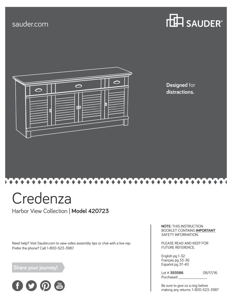
Sauder Credenza 420723 User manual

Sauder

Sauder Credenza 420723 User manual
Sauder worksense PALO ALTO 427795 User manual

Sauder

Sauder worksense PALO ALTO 427795 User manual

Sauder Pogo 414433 User manual

Sauder

Sauder Pogo 414433 User manual

Sauder Cannery Bridge 429515 User manual

Sauder

Sauder Cannery Bridge 429515 User manual

Sauder International Lux 417828 User manual

Sauder

Sauder International Lux 417828 User manual

Sauder worksense MASON PEAK Credenza 427805 User manual

Sauder

Sauder worksense MASON PEAK Credenza 427805 User manual

Sauder 420477 User manual

Sauder

Sauder 420477 User manual

Sauder 431238 User manual

Sauder

Sauder 431238 User manual

Sauder Palladia Highboy 411626 User manual

Sauder

Sauder Palladia Highboy 411626 User manual

Sauder WHISKER User manual

Sauder

Sauder WHISKER User manual

Sauder Via 401443 User manual

Sauder

Sauder Via 401443 User manual

Sauder Aspen Post 427022 User manual

Sauder

Sauder Aspen Post 427022 User manual

Sauder SmartCenter Edge Water 413092 User manual

Sauder

Sauder SmartCenter Edge Water 413092 User manual

Sauder North Avenue 422313 User manual

Sauder

Sauder North Avenue 422313 User manual

Sauder Carson Forge 419575 User manual

Sauder

Sauder Carson Forge 419575 User manual

Sauder Manhattan Gate 429251 User manual

Sauder

Sauder Manhattan Gate 429251 User manual

Sauder Mates Bed 423003 User manual

Sauder

Sauder Mates Bed 423003 User manual

Sauder 411606 User manual

Sauder

Sauder 411606 User manual

Popular Indoor Furnishing manuals by other brands

Lightolier Lytespan 6255 specification

Lightolier

Lightolier Lytespan 6255 specification

Furniture of America FOA7887Q Assembly instructions

Furniture of America

Furniture of America FOA7887Q Assembly instructions

Furniture of America FOA7225-M Assembly instructions

Furniture of America

Furniture of America FOA7225-M Assembly instructions

Coaster 203501Q Assembly instructions

Coaster

Coaster 203501Q Assembly instructions

Furniture of America Plymouth CM3979PC-2PK Assembly instructions

Furniture of America

Furniture of America Plymouth CM3979PC-2PK Assembly instructions

Teknion WWComplements WWCOMP HA Installation guides

Teknion

Teknion WWComplements WWCOMP HA Installation guides

Ethnicraft BED WITH SLATS Assembly instruction

Ethnicraft

Ethnicraft BED WITH SLATS Assembly instruction

Target fairfax TGCRCNTB01 Assembly instructions

Target

Target fairfax TGCRCNTB01 Assembly instructions

Hillsdale Furniture KENDALL DUO PANEL 100377-100690 quick start guide

Hillsdale Furniture

Hillsdale Furniture KENDALL DUO PANEL 100377-100690 quick start guide

Ballard Designs MELISSI TC315 quick start guide

Ballard Designs

Ballard Designs MELISSI TC315 quick start guide

TUHOME Furniture Kava BLB 6551 Assembly instructions

TUHOME Furniture

TUHOME Furniture Kava BLB 6551 Assembly instructions

Safavieh Furniture Bedwyr COF7305A manual

Safavieh Furniture

Safavieh Furniture Bedwyr COF7305A manual

Ameriwood HOME 7965926COM Instruction booklet

Ameriwood HOME

Ameriwood HOME 7965926COM Instruction booklet

Triarch 31433 Assembly instructions

Triarch

Triarch 31433 Assembly instructions

LDI SAFCO Medina 6827 instructions

LDI

LDI SAFCO Medina 6827 instructions

Home Decorators Collection 4115 swivel stool 1004248937 Use and care guide

Home Decorators Collection

Home Decorators Collection 4115 swivel stool 1004248937 Use and care guide

Amart Furniture VALKYRIE 74935 Assembly instruction

Amart Furniture

Amart Furniture VALKYRIE 74935 Assembly instruction

Kettler Palma Duo Relaxer Set 0193338-2100 quick start guide

Kettler

Kettler Palma Duo Relaxer Set 0193338-2100 quick start guide

manuals.online logo
manuals.online logoBrands
  • About & Mission
  • Contact us
  • Privacy Policy
  • Terms and Conditions

Copyright 2025 Manuals.Online. All Rights Reserved.