manuals.online logo
Brands
  1. Home
  2. •
  3. Brands
  4. •
  5. Sauder
  6. •
  7. Indoor Furnishing
  8. •
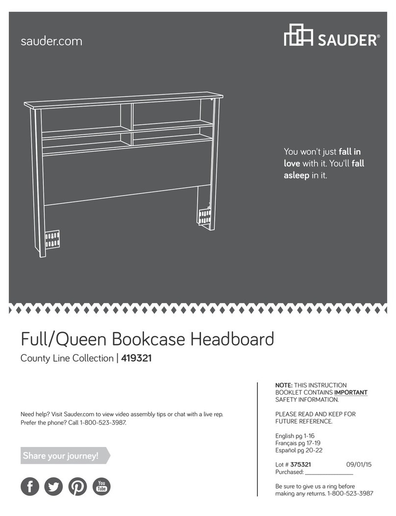
  9. Sauder Pallada Series 411843 User manual

Sauder Pallada Series 411843 User manual

Need help? Visit Sauder.com to view video assembly tips or chat with a live rep.
Prefer the phone? Call 1-800-523-3987.
Share your journey!
sauder.com
Your holder for all
things awesome.
NOTE: THIS INSTRUCTION
BOOKLET CONTAINS IMPORTANT
SAFETY INFORMATION.
PLEASE READ AND KEEP FOR
FUTURE REFERENCE.
English pg 1-27
Français pg 28-31
Español pg 32-35
Lot # 397181 10/03/16
Purchased: __________________
Be sure to give us a ring before
making any returns. 1-800-523-3987
Armoire
Palladia Collection | Model 411843
Assembly Tools Required
Part Identification
Hardware Identification
Assembly Steps
Français
Español
Safety
Warranty
Hammer
Not actual size
No. 2 Phillips Screwdriver
Tip Shown Actual Size
Skip the power trip.
This time.
Table of Contents
Now you know
our ABCs.
2-3
4-5
6-27
28-31
32-35
36-38
39
Part Identification
A2 RIGHT END (1)
B2 LEFT END (1)
C2 TOP (1)
D BOTTOM (1)
E SHELF (1)
F2 BACK (1)
G DOOR (2)
H SKIRT (1)
M65 DRAWER BRACE (1)
J DRAWER FRONT (1)
N FRONT MOLDING (1)
O SHELF MOLDING (1)
P BOTTOM MOLDING (1)
Q RIGHT MOLDING (1)
R LEFT MOLDING (1)
S MOLDING (2)
R2 PLINTH (2)
D260 RIGHT DRAWER SIDE (1)
D261 DRAWER BACK (1)
D263 LEFT DRAWER SIDE (1)
D996 DRAWER BOTTOM (1)
411843 www.sauder.com/servicesPage 2
åWhile not all parts are labeled, some of the parts will have a label or an inked letter on the edge
to help distinguish similar parts from each other. Use this part identification to help identify similar parts.
Part Identification
A2
B2
C2
D
E
F2
G
G
H
J
N
OP
Q
R
R2
R2
S
S
D260
D263
D996
D261
411843www.sauder.com/services Page 3
M65
åScrews are shown actual size. You may receive extra hardware with your unit.
Hardware Identification
TIE PLATE - 2
GG
METAL
BRACKET - 5
FF
KK ROD HANGER - 2
ZTWIST-LOCK®
FASTENER - 14
MOLDING
CONNECTOR - 2
JJ
DOOR STOP - 2
LL KNOB - 4
MM
HIDDEN
CAM - 7
AA2 CAM DOWEL - 3
CC2
CAM
SCREW - 4
BB2
YROD - 1
DRAWER FRONT
BRACKET - 1
OO
411843 www.sauder.com/servicesPage 4
40DA UNIVERSAL CABINET RAIL - 2 40DC DRAWER RIGHT - 1 40DD DRAWER LEFT - 1
DD HINGE - 6
SAFETY STRAP - 1
Locate this nylon SAFETY
STRAP (60M) to be used
later in assembly. Do not
accidentally throw away.
60M SAFETY DRYWALL
ANCHOR - 1
61M
WASHER - 1
13M
TOP DRAWER FRONT
BRACKET - 1
NN
Hardware Identification
åScrews are shown actual size. You may receive extra hardware with your unit.
BLACK 1-1/8" MACHINE SCREW - 2
SS
GOLD 1" MACHINE SCREW - 2
TT BLACK 9/16" LARGE HEAD SCREW - 21
UU
BLACK 1-1/4" FLAT HEAD SCREW - 11
RR
3S GOLD 5/16" FLAT HEAD SCREW - 8
BLACK 1/2" FLAT HEAD SCREW - 12
VV NAIL - 50
XX
411843www.sauder.com/services Page 5
30S BLACK 1-9/16" FLAT HEAD SCREW - 5
11L WARNING LABEL - 1
(Refer to step 20 for proper location and application)
WARNING AVERTISSEMENT ADVERTENCIA
Serious or fatal crushing injuries can
occur from furniture tipover.
To help prevent tipover:
• Install tipover restraint provided.
• Place heaviest items in the lower drawers.
• Unless specifically designed to
accommodate, do not set TVs or other
heavy objects on top of this product.
• Never allow children to climb or hang on
drawers, doors, or shelves.
• Never open more than one drawer at a time.
(OR)
• Do not defeat or remove the drawer
interlock system.
Use of tipover restraints may only reduce,
but not eliminate, the risk of tipover.
This is a permanent label. Do not remove.
Des blessures graves ou fatales par écrasement
peuvent survenir si le mobilier bascule. Pour
prévenir le basculement:
• Installer le dispositif anti-basculement fourni.
• Placer les articles plus lourds dans les tiroirs inférieurs.
• Sauf si le meuble a été conçu spécialement à
cette fin, ne pas mettre de téléviseur ou d’autre
objets lourds sur le dessus de ce meuble.
• Ne jamais laisser d’enfants grimper sur les
tiroirs, les portes ou les étagères ou s’y agripper.
• Ne jamais ouvrir plus d’un tiroir à la fois.
(OU)
• Ne pas démanteler ou enlever le système de
verrouillage pour tiroir.
L’utilisation de dispositifs anti-basculement peut
réduire le risque de basculement, mais pas l’éliminer.
Cette étiquette est permanente. Ne pas l’enlever.
Lesiones graves o fatales por aplastamiento, pueden
ocurrir por el volcar de los muebles. Para ayudar a
prevenir que se volqué:
• Instalar la contención brindada para evitar que se volqué.
• Coloque los artículos más pesados en los cajones
inferiores.
• A menos que sea específicamente diseñado para
acomodar, no establezca televisores u otros objetos
pesados en la parte superior de este producto.
• Nunca permita que los niños se suban o se cuelguen
de cajones, puertas o estantes.
• Nunca abra más de un cajón a la vez.
(O)
• No anule o elimine el sistema de bloqueo de los cajones.
El uso de la contención puede solamente reducir, pero
no eliminar, el riesgo de volcar.
Esta es una etiqueta permanente. No remover.
10/16 395783
Step 1 Look for this icon. It means a
video assembly tip is available at
www.sauder.com/services/tips
411843 www.sauder.com/servicesPage 6
(14 used)
Z
Z
Z
Do not tighten the TWIST-LOCK® FASTENERS in this step.
å Assemble your unit on a carpeted floor or on the empty
carton to avoid scratching your unit or the floor.
å To begin assembly, push a SAUDER TWIST-LOCK®
FASTENER (Z) into the large holes in the ENDS (A2 and B2).
å Repeat this step for the BOTTOM (D) and SHELF (E).
A2
B2
Scan this QR code or go to this address:
http://qr.sauder.com/?ID=1610
to watch a video on how to assemble your unit.
Step
411843www.sauder.com/services Page 7
å Push seven HIDDEN CAMS (AA2) into the BOTTOM (D),
SHELF (E), and DRAWER BRACE (M65). Then, insert the
metal end of three CAM DOWELS (CC2) into the HIDDEN
CAMS in the SHELF (E).
Step 2
Insert the metal end of the CAM
DOWEL into the HIDDEN CAM.
Arrow
Do not tighten the HIDDEN CAMS in this step.
Arrow
Arrow
The arrow in the HIDDEN
CAM must point toward the
hole in the edge of the board.
Hole
AA2
Arrow
AA2
CC2
D
E
M65
Step
å Turn four CAM SCREWS (BB2) into the DRAWER FRONT (J)
and BOTTOM MOLDING (P)
.
Step 3
411843 www.sauder.com/servicesPage 8
BB2
J
P
Step
411843www.sauder.com/services Page 9
Step 4
å Tap two MOLDING CONNECTORS (JJ) into the notches
in the MOLDINGS (N, Q, and R).
N
Q
R
Flat end
Flat end
JJ
JJ
Just think. The sooner
you do this, the sooner
you do something else.
Use your hammer to tap the MOLDING CONNECTORS (JJ) into the notches in the MOLDINGS.
Step
å Fasten the MOLDINGS (N, Q, and R) to the TOP (C2). Use
seven BLACK 1-1/4" FLAT HEAD SCREWS (RR).
å NOTE: Do not overtighten the SCREWS into the TOP.
å Push a DOOR STOP (LL) into the hole in the
FRONT MOLDING (N).
Step 5
411843 www.sauder.com/servicesPage 10
BLACK 1-1/4" FLAT HEAD SCREW
(7 used in this step)
RR
LL
N
Q
R
C2
Rounded edge
Step
411843www.sauder.com/services Page 11
Step 6
å Fasten the UNIVERSAL CABINET RAILS* (40DA) to the ENDS (A2
and B2). Use four GOLD 5/16" FLAT HEAD SCREWS (3S) through
holes #1 and #4.
å Fasten the ROD HANGERS (KK) to the ENDS (A2 and B2). Use
two BLACK 9/16" LARGE HEAD SCREWS (UU).
å *patent pending glide system
GOLD 5/16" FLAT HEAD SCREW
(4 used for the CABINET RAILS)
3S
1
2
3
4
1
234
Glide end
Glide end
KK
BLACK 9/16" LARGE HEAD SCREW
(2 used in this step)
UU
Edge with
TWIST-LOCK®
FASTENER
Edge with
TWIST-LOCK®
FASTENER
B2
A2
VIEW THE DRAWER GLIDE VIDEO
StepStep 7
å Fasten the LEFT END (B2) to the LEFT MOLDING (R) on
the TOP (C2). Tighten two TWIST-LOCK® FASTENERS.
411843 www.sauder.com/servicesPage 12
Edge with
TWIST-LOCK®
FASTENER
How to use the SAUDER TWIST-LOCK®FASTENER
1. Insert the dowel end of the FASTENER into the hole of the
adjoining part.
NOTE: The dowel end of the FASTENER must remain fully
inserted in the hole of the adjoining part while locking
the FASTENER.
2. Tighten the FASTENER with a Phillips screwdriver as tight
as possible.
Dowel end
Rounded edge
B2
C2
R
Surface with
TWIST-LOCK®
FASTENERS
Do not stand the unit upright without the
BACK fastened. The unit may collapse.
Caution
Step
411843www.sauder.com/services Page 13
å Fasten the BOTTOM (D) and SHELF (E) to the LEFT
END (B2). Tighten four TWIST-LOCK® FASTENERS.
Step 8
Surface with
TWIST-LOCK®
FASTENERS
Surface with
TWIST-LOCK®
FASTENERS
B2
D
E
Edge with CAM DOWELS
Edge with holes
Step
å Fasten the RIGHT END (A2) to the BOTTOM (D),
SHELF (E), and RIGHT MOLDING (Q) on the TOP (C2).
Tighten six TWIST-LOCK® FASTENERS.
Step 9
411843 www.sauder.com/servicesPage 14
A2
C2
D
E
Q
Edge with
TWIST-LOCK®
FASTENER
Don't worry. It isn't
Rome. This can be built
in a day.
Step
411843www.sauder.com/services Page 15
å Fasten the SHELF MOLDING (O) to the SHELF (E).
Tighten three HIDDEN CAMS.
å Fasten the BOTTOM MOLDING (P) to the BOTTOM (D).
Tighten three HIDDEN CAMS.
å Push a DOOR STOP (LL) into the hole in the SHELF (E).
Step 10
D
E
O
P
LL
Curved edge
Start Tighten
Arrow
Minimum
190 degrees
Caution
Risk of damage or
injury. HIDDEN CAMS
must be completely
tightened. HIDDEN
CAMS that are not
completely tightened
may loosen, and parts
may separate. To
completely tighten:
Arrow
Maximum
210 degrees
Step
å Fasten five METAL BRACKETS (FF) to the BOTTOM (D).
Use five BLACK 9/16" LARGE HEAD SCREWS (UU).
å Fasten the PLINTHS (R2) to the ENDS (A2 and B2) and
BOTTOM (D). Tighten two TWIST-LOCK® FASTENERS
and use two BLACK 9/16" LARGE HEAD SCREWS (UU).
å Fasten the SKIRT (H) to the BOTTOM (D). Use three
BLACK 9/16" LARGE HEAD SCREWS (UU).
Step 11
411843 www.sauder.com/servicesPage 16
A2
B2
D
FF
R2
R2
BLACK 9/16" LARGE HEAD SCREW
(10 used for the METAL BRACKETS
UU
Curved edge
Curved edge
H
Step
411843www.sauder.com/services Page 17
å Carefully turn your unit over onto its front edges. Unfold the
BACK (F2) and lay it over your unit.
å Make equal margins along all four edges of the BACK (F2). Push
on opposite corners of your unit if needed to make it "square".
å Fasten the BACK (F2) to your unit using the NAILS (XX).
å NOTE: Be sure to tap NAILS into the holes that line up over
the SHELF (E).
å Fasten the TIE PLATES (GG) to the SKIRT (H) and
PLINTHS (R2). Use four BLACK 9/16" LARGE
HEAD SCREWS (UU).
Step 12
Unfinished surface
These holes must line
up over the SHELF (E).
NAIL
(50 used in this step)
XX
GG
BLACK 9/16" LARGE HEAD SCREW
(4 used for the TIE PLATES)
UU
H
R2
R2
F2
Do not stand the unit upright without the
BACK fastened. The unit may collapse.
Caution
Step
å Fasten the HINGES (DD) to the DOORS (G). Use
twelve BLACK 1/2" FLAT HEAD SCREWS (VV).
Step 13
411843 www.sauder.com/servicesPage 18
DD
BLACK 1/2" FLAT HEAD SCREW
(12 used in this step)
VV
DD
G
G
Step 14
411843www.sauder.com/services Page 19
BLACK 1-1/8" MACHINE SCREW
(2 used for the KNOBS)
SS
MM
A2
G
å Carefully stand your unit upright.
å Before fastening the DOOR to your unit, be sure the
mounting screw is against the stops as shown in the
diagram. If it isn't, loosen the mounting screw to slide it
against the stops. Then tighten the mounting screw.
å Fasten a DOOR (G) to the RIGHT END (A2). Use the screws
in the HINGES. See the next step for door adjustments.
å Fasten a KNOB (MM) to the DOOR (G). Use a BLACK 1-1/8"
MACHINE SCREW (SS).
å Repeat this step for the other DOOR (G).
Mounting
screw
Stop
Hinge
Pro Tip: Lift with your
legs. And, you know,
your arms.
Step 15
411843 www.sauder.com/servicesPage 20
å Refer to the enlarged diagram to identify the parts
on the HINGES.
å The DOORS may need some adjustments. Follow
the text below to make needed adjustments.
å DOOR ADJUSTMENTS:
To adjust the DOORS from side to side (horizontal),
turn the adjusting screw in or out.
å To adjust the DOORS up and down (vertical), loosen
both vertical adjustment screws. Move the DOORS
up or down to the desired location. Tighten the
screws after making adjustments.
å To adjust the DOORS in or out (depth), loosen the
mounting screw one turn and move the DOORS in
or out, as needed. Tighten the mounting screw after
making adjustments.
Adjusting screw (horizontal)
Mounting screw (depth)
(vertical adjustment)

Other Sauder Indoor Furnishing manuals

Sauder Office Port Series User manual

Sauder

Sauder Office Port Series User manual

Sauder 408739 User manual

Sauder

Sauder 408739 User manual

Sauder Barrister Lane 414836 User manual

Sauder

Sauder Barrister Lane 414836 User manual

Sauder OfficeWorks AFFIRM 426285 User manual

Sauder

Sauder OfficeWorks AFFIRM 426285 User manual

Sauder Portage Park 426281 User manual
Sauder

Sauder Portage Park 426281 User manual

Sauder Worksense BERGEN CIRCLE 426288 User manual

Sauder

Sauder Worksense BERGEN CIRCLE 426288 User manual

Sauder HomePlus 411965 User manual

Sauder

Sauder HomePlus 411965 User manual

Sauder Worksense BERGEN CIRCLE 427476 User manual

Sauder

Sauder Worksense BERGEN CIRCLE 427476 User manual

Sauder 423392 User manual

Sauder

Sauder 423392 User manual

Sauder 411371 User manual

Sauder

Sauder 411371 User manual

Sauder Harbor View 417586 User manual

Sauder

Sauder Harbor View 417586 User manual

Sauder Hammond 428246 User manual

Sauder

Sauder Hammond 428246 User manual

Sauder Office Port 408294 User manual

Sauder

Sauder Office Port 408294 User manual

Sauder Briarbrook 430070 User manual

Sauder

Sauder Briarbrook 430070 User manual

Sauder Edge Water Series User manual

Sauder

Sauder Edge Water Series User manual

Sauder 412720 User manual

Sauder

Sauder 412720 User manual

Sauder Harbor View Armoire 415003 User manual

Sauder

Sauder Harbor View Armoire 415003 User manual

Sauder Carson Forge 414444 User manual

Sauder

Sauder Carson Forge 414444 User manual

Sauder OfficeWorks AFFIRM 427422 User manual

Sauder

Sauder OfficeWorks AFFIRM 427422 User manual

Sauder 413854 User manual

Sauder

Sauder 413854 User manual

Sauder Cannery Bridge 429510 User manual

Sauder

Sauder Cannery Bridge 429510 User manual

Sauder Camden 101730 User manual

Sauder

Sauder Camden 101730 User manual

Sauder Whitaker Point 429369 User manual

Sauder

Sauder Whitaker Point 429369 User manual

Sauder 417886 User manual

Sauder

Sauder 417886 User manual

Popular Indoor Furnishing manuals by other brands

RiverRidge 06-086 Assembly instructions

RiverRidge

RiverRidge 06-086 Assembly instructions

Happy Babies RN18 Assembly instructions

Happy Babies

Happy Babies RN18 Assembly instructions

MEGA MOBEL 0770-HB 3 Assembly instructions

MEGA MOBEL

MEGA MOBEL 0770-HB 3 Assembly instructions

GoodHome atomia 5036581054632 manual

GoodHome

GoodHome atomia 5036581054632 manual

International Concepts TC-937 Assembly instructions

International Concepts

International Concepts TC-937 Assembly instructions

Func COOEE WALL Assembly guide

Func

Func COOEE WALL Assembly guide

Monarch Specialties I 7056 Assembly instructions

Monarch Specialties

Monarch Specialties I 7056 Assembly instructions

Garden Treasures LG-19005B-3PC Quick reference guide

Garden Treasures

Garden Treasures LG-19005B-3PC Quick reference guide

Office Star Products TEX220 Assembly instructions

Office Star Products

Office Star Products TEX220 Assembly instructions

KidKraft Toy Caddy 15901C Assembly instructions

KidKraft

KidKraft Toy Caddy 15901C Assembly instructions

Coaster 552052 Assembly instructions

Coaster

Coaster 552052 Assembly instructions

Canvas 168-0038-4 Assembly instructions

Canvas

Canvas 168-0038-4 Assembly instructions

Habitat Ivoine 820242 manual

Habitat

Habitat Ivoine 820242 manual

Innovation Living IDI 2 ARMS manual

Innovation Living

Innovation Living IDI 2 ARMS manual

Flash Furniture WX-5L203-BK-GR-GG Assembly instructions

Flash Furniture

Flash Furniture WX-5L203-BK-GR-GG Assembly instructions

Whittier Wood 1370GACl Assembly instructions

Whittier Wood

Whittier Wood 1370GACl Assembly instructions

Hillsdale Furniture 51115 manual

Hillsdale Furniture

Hillsdale Furniture 51115 manual

Kiddicare Jessica Wardrobe Assembly instructions

Kiddicare

Kiddicare Jessica Wardrobe Assembly instructions

manuals.online logo
manuals.online logoBrands
  • About & Mission
  • Contact us
  • Privacy Policy
  • Terms and Conditions

Copyright 2025 Manuals.Online. All Rights Reserved.