manuals.online logo
Brands
  1. Home
  2. •
  3. Brands
  4. •
  5. Savant
  6. •
  7. Controllers
  8. •
  9. Savant SmartControl 12 User manual

Savant SmartControl 12 User manual

Box Contents
(1) SmartControl 12 (SSC-0012-00)
(1) Installation Kit SmartControl 12 (075-0180-xx)
(1) Mounting Plate (074-0577-xx)
(4) 6-pin Screw Down Plug-in Connector (028-9352-xx)
(1) 12V DC 1.6A Power Supply (025-0166-xx)
(1) Cable Tie (014-0071-xx)
(1) Quick Reference Guide (this document)
Specifications
Environmental
Environmental
Temperature
32° to 104° F (0° to 40° C)
Humidity
10% to 80% RH (non-condensing)
Dimensions and Weight
Height
1.40 in (3.5 cm)
Width
6.00 in (15.2 cm)
Depth
3.20 in (8.1 cm)
Weight
Net: 0.50 lb (0.22 kg)
Weight
Shipping: 1.50 lb (0.68 kg)
Power
Power
Input Power (Max)
12V DC 1.6A
Max Power
18 watts
Compliance
Compliance
Safety and
Emissions
FCC Part 15 | CE Mark | C-Tick
RoHS
Compliant
Minimum Supported Release
Savant OS
da Vinci 7.0
Network Requirements
Savant requires the use of business class/commercial grade network
equipment throughout the network to ensure the reliability of
communication between devices. These higher quality components
also allow for more accurate troubleshooting when needed.
Connect all Savant devices to the same local area network (LAN) or
subnet as the host. Savant recommends not implementing any type
of traffic or packet shaping in your network topology for the Savant
devices as this may interfere with performance.
Network Configuration
To ensure that the IP Address will not change due to a power outage,
a static IP Address or DHCP reservation should be configured.
Savant recommends using DHCP reservation within the router. By
using this method, static IP Addresses for all devices can be
managed from a single UI avoiding the need to access devices
individually.
Setting DHCP reservation varies from router to router. Refer to the
documentation for the router to configure DHCP reservation.
Network Changes
Savant recommends performing one of the following steps to refresh
the IP connection after connecting to a new network, changing
routers, or if the IP Address range is changed in the current router.
This will reset any IP connection and ensure that the host is
communicating with the network correctly.
•Cycle Power
Disconnect the controller from the AC power source for 15
seconds and then reconnect.
•Hot Plug the Ethernet (LAN) Connection
Disconnect the Ethernet (LAN) connection from the controller for
15 seconds and then reconnect.
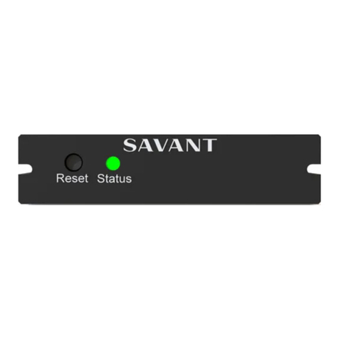
Front Panel
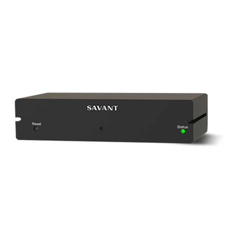
Reset Button
Press and hold for 5 seconds while powered On
to clear network settings. Status LED will blink
rapidly when reset is complete.
Status LED
Blinks Once: No IP Address
Blinks Twice: Waiting for Host Connection
Blinks Three Times: Host Connection Lost
Solid: Connected to Host
Rear Panel
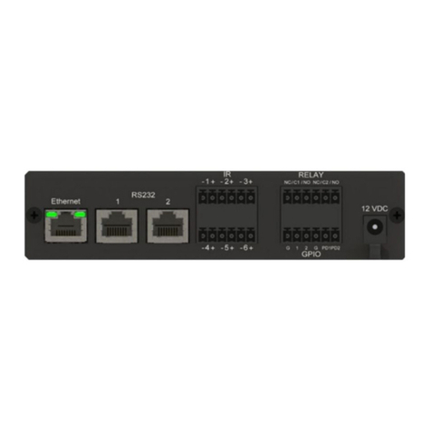
Ethernet
10/100 Base-T auto-negotiating port with Link/
Activity.
LEDs: 8-pin RJ-45 female.
See items B and C for LED functionality.
Link LED
Off: Ethernet link is not established.
Green Solid: Ethernet link is established.
Green Blinking: Ethernet activity is occurring.
Data
Rate LED
Off: 10 Mbps data rate
Green: 100 Mbps data rate
RS-232
8-pin RJ-45 female. Used to transmit and receive
serial binary data to and from serial controllable
devices. Ports 1-2 RS-232 - CTS/RTS handshaking.
CTS/RTS Handshaking availability based on
component profile. See RS-232 Wiring and
Connections.
IR
Used to send IR signals to control devices with an
IR input or IR receiver via an IR flasher (5V
tolerant only). 6-pin Screw Down Plug-in
Connector.See IR Wiring for important
precautions regarding IR functionality before
making any connections.
GPIO (General Purpose Input and Output Ports) 6-pin
Screw Down Plug-in Connector. See GPIO Wiring for
pinouts.
GPIO (General Purpose Input and Output Ports) 6-pin
Screw Down Plug-in Connector. See GPIO Wiring for
pinouts.
GPIO
Input
When configured as an input, the processor will
look for a low (<0.8V DC) or high (>2.4V DC )
state.
Minimum 0V DC / Maximum 12V DC
GPIO
Output
When configured as an output, the port provides
a binary output of 0-12V DC 150mA max.
Normally Open / Normally Closed - Relays
6-pin Screw Down Plug-in Connector
Normally Open / Normally Closed - Relays
6-pin Screw Down Plug-in Connector
Relay
Dry contacts (open/closed) to control devices
requiring basic on/offoperation. DC Voltage Max:
30V DC 1A.
6-pin Screw Down Plug-in Connector
Input
Power
12V DC 1.6A – Connect to included power supply.
Cable
Lance
Use with included cable tie to secure power
supply connection.
SSC-0012-00 | 009-1255-02 | 160308
45 Perseverance Way, Hyannis, MA 02601
Copyright © 2016 Savant Systems, LLC
1
of
2
Savant.com | 508.683.2500
Savant® SmartControl 12
Quick Reference Guide
For Product Info
RS-232 Wiring and Connections
Notes:
•CTS/RTS handshaking is supported for flow control based on the
profile used in the configuration.
•The SSC-0012 does not support RS-422/485.
RJ-45 to DB9 Adapters
Refer to the RS-232 Conversion to DB9 and RS-422/485 Pinout
Application Note located on the Savant Customer Community for
more information on the RJ-45 to DB9 adapters offered by Savant.
IR Wiring
IR connections are made using 6-pin Screw Down Plug-in
Connectors supplied with controller. The wire slips into the hole and
locks with the screw located at the top of the connector.
IMPORTANT! IR Wiring Precautions
•Ensure that all IR emitters are within 15 feet (4.6 meters) from the
controllers location.
•Use of 3rd party flashing IR emitters with Talk Back is not
recommended. These types of emitters can draw voltage away
from the IR signal that can degrade IR performance.
IR Port Connector Pinout
Note:
While not shown in a diagram above, connections IR4 to IR6 follow
the same wiring as IR1 to IR3.
GPIO Wiring
General Purpose Input/Outputs (GPIO) are binary I/O ports used on
Savant controllers to trigger an action within the system. Events can
control a device, such as turning on an amplifier (output) or detecting a
state change for a device (input) to perform a workflow. Pins 1-4 are
used for input or output depending on configuration.
GPIO Pull Down Resistor (PD) Usage
The GPIO pins are by default configured as inputs and pulled high to
12V while the host is booting up. To pull the GPIO signal low during a
host reboot and/or power cycle, a jumper wire can be connected
between a GPIO pin and its corresponding PD1 and PD2 pin. Doing this
adds a 1k ohm resistor between the GPIO pin and ground which keeps
the GPIO output below 0.8V while the host is rebooting.
GPIO Connector Pinout
Relay Wiring
Relays are used when a contact closure (normally open or normally
closed) is needed to activate a device such as raising or lowering
shades, opening or closing a gate, etc.
Relay Connector Pinout
Making Connections
1. Remove Power if power is applied.
2. Pull to remove the terminal block from the rear of the controller.
3. With a small flat bladed screwdriver, turn the screws on the top of
connector counterclockwise until the silver crimps in the front of the
connector opens enough to slide the wires into the square slots.
4. Insert one of the stripped wires from the device being controlled
into its respective slot in the connector. Refer to the diagrams.
5. Turn the screw clockwise until the screw tightens around the wire.
Tug on the wire a bit to verify it is installed securely. Do not allow
more than 1/2 inch of stripped wire exit from the rear of the
connector.
6. Repeat for each wire till all wires are installed in that connector.
7. Repeat steps above for all connectors as required.
8. Plug terminal blocks back into rear of the controller.
9. Reapply power
Additional Documentation
Refer to the following documents located on the Savant Customer
Community for additional information.
•SmartControl 12 SSC-0012 Deployment Guide (009-1268-xx)
•Relay and General Purpose Input/Output Profiles: Application Note
•RS-232 Conversion to DB-9 and RS-422/485 Pinout: Application
Note
•Savant Controllers Family video in the Savant University pages
SSC-0012-00 | 009-1255-02 | 160308
45 Perseverance Way, Hyannis, MA 02601
Copyright © 2016 Savant Systems, LLC
2
of
2
Savant.com | 508.683.2500

Other manuals for SmartControl 12

3

This manual suits for next models

1

Other Savant Controllers manuals

Savant SmartControl SSC-W003I User manual

Savant

Savant SmartControl SSC-W003I User manual

Savant Pro Host User manual

Savant

Savant Pro Host User manual

Savant SmartMediaPro 6 Quick reference guide

Savant

Savant SmartMediaPro 6 Quick reference guide

Savant SmartControl 3 User manual

Savant

Savant SmartControl 3 User manual

Savant SmartLighting 2 User manual

Savant

Savant SmartLighting 2 User manual

Savant SmartControl 3 User manual

Savant

Savant SmartControl 3 User manual

Savant SmartControl 3 User manual

Savant

Savant SmartControl 3 User manual

Savant LCB-DMX1 Quick reference guide

Savant

Savant LCB-DMX1 Quick reference guide

Savant HST-4001 User manual

Savant

Savant HST-4001 User manual

Savant SmartControl 3 User manual

Savant

Savant SmartControl 3 User manual

Savant SmartControl 2 User manual

Savant

Savant SmartControl 2 User manual

Savant SmartControl 3 Quick reference guide

Savant

Savant SmartControl 3 Quick reference guide

Savant LCB-DMX1 Quick reference guide

Savant

Savant LCB-DMX1 Quick reference guide

Savant CPT-1212 User manual

Savant

Savant CPT-1212 User manual

Savant SmartControl 7 User manual

Savant

Savant SmartControl 7 User manual

Savant WIF S104 Series User manual

Savant

Savant WIF S104 Series User manual

Savant SmartLighting 2 User manual

Savant

Savant SmartLighting 2 User manual

Savant SmartControl 2 Quick reference guide

Savant

Savant SmartControl 2 Quick reference guide

Savant SmartControl RS232 User manual

Savant

Savant SmartControl RS232 User manual

Savant S2 Quick reference guide

Savant

Savant S2 Quick reference guide

Savant SmartControl 12 Quick reference guide

Savant

Savant SmartControl 12 Quick reference guide

Savant SmartLighting 18 User manual

Savant

Savant SmartLighting 18 User manual

Savant Director Lite HST-DIRECTORLITE User manual

Savant

Savant Director Lite HST-DIRECTORLITE User manual

Savant SSC-W485 User manual

Savant

Savant SSC-W485 User manual

Popular Controllers manuals by other brands

CyberPower V-Armor600E user manual

CyberPower

CyberPower V-Armor600E user manual

Toshiba nv Series instruction manual

Toshiba

Toshiba nv Series instruction manual

LIXiSE LXC620 user manual

LIXiSE

LIXiSE LXC620 user manual

PROTRONIX UR10-AIR user manual

PROTRONIX

PROTRONIX UR10-AIR user manual

HM Digital PS-202 user guide

HM Digital

HM Digital PS-202 user guide

Sealey RS22 instructions

Sealey

Sealey RS22 instructions

Rockwell Automation Allen-Bradley PLC-2/30 Assembly and installation manual

Rockwell Automation

Rockwell Automation Allen-Bradley PLC-2/30 Assembly and installation manual

HSAJET MiniKey user manual

HSAJET

HSAJET MiniKey user manual

AEA PAKRATT PK-232 Technical reference manual

AEA

AEA PAKRATT PK-232 Technical reference manual

CSN S.A.T. instruction manual

CSN

CSN S.A.T. instruction manual

Blonder tongue BT-HE-DASHBOARD user manual

Blonder tongue

Blonder tongue BT-HE-DASHBOARD user manual

ATTO Technology XstreamCORE ET 8200 Installation and operation manual

ATTO Technology

ATTO Technology XstreamCORE ET 8200 Installation and operation manual

BIFFI GIGS 0.3 Use and maintenance manual

BIFFI

BIFFI GIGS 0.3 Use and maintenance manual

HeatStar JET20 Operating instructions and owner's manual

HeatStar

HeatStar JET20 Operating instructions and owner's manual

HP HPE VAN SDN Controller 2.7 Administrator's guide

HP

HP HPE VAN SDN Controller 2.7 Administrator's guide

Festo SPC200 Series manual

Festo

Festo SPC200 Series manual

ABB ACS580-01 drives Hardware manual

ABB

ABB ACS580-01 drives Hardware manual

Siemens CP 1612 A2 operating instructions

Siemens

Siemens CP 1612 A2 operating instructions

manuals.online logo
manuals.online logoBrands
  • About & Mission
  • Contact us
  • Privacy Policy
  • Terms and Conditions

Copyright 2025 Manuals.Online. All Rights Reserved.