15. CLEANING & MAINTENANCE FOR COIN SELECTOR.............................................................. 49
15-1 Handling the Coin Jam ......................................................................................................... 49
15-2 CLEANING & MAINTENANCE FOR COIN SELECTOR ..................................................... 49
15-3 Coin Insert Test..................................................................................................................... 50
16. HOW TO REPLACE THE PANEL & LIGHTING TUBE FOR BILLBOARD ................................. 50
16-1 Replace the lamp box & lighting tube................................................................................... 50
16-2 Replace the lamp panel. ....................................................................................................... 52
17. HOW TO REPLACE THE LIGHTING BULB FOR START BUTTON........................................... 53
17-1 Access to the Start Switch and Lamp housing is gained by first removing the Start Button
Plate...................................................................................................................................... 53
17-2 Remove the Button Plate from the Control Panel to gain access to the Switch and Lamp
housing. ................................................................................................................................ 53
17-3 Once the Button plate has been removed to reveal the Switch and Lamp housing, do not
pull the assembly arbitrarily, otherwise, may lead to the damage....................................... 54
17-4 Holding the Lamp Housing between your index finger and thumb, gently remove the
housing from the button cover. Always hold firmly onto the housing but not the wires, and
remove the lamp from the lamp housing, The Lamp is a push-fit and should not be
twisted in its housing. ........................................................................................................... 54
18. COMMON TROUBLESHOOTING................................................................................................. 55
18-1 Start the game , the aim point in the screen cannot be movable when swinging the
controller left and right.......................................................................................................... 55
18-2 Start the game, the aim point in the screen cannot be movable when swinging the
controller up and down. ........................................................................................................ 56
19. MAINFRAME POSITION ............................................................................................................... 57
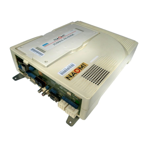
19-1 RINGEDGE2 –LOCATION .................................................................................................. 57
19-2 CLEANING THE RINGEDGE2 ............................................................................................ 59
19-3 COMPOSITION OF RINGEDEGE2..................................................................................... 60
19-4 Error Warnning Display ........................................................................................................ 61
21. PARTS LIST................................................................................................................................... 64
21-1 FINAL ASSEMBLY DRAWINGTRF-55-0000................................................................. 65
21-2 mainframeTRF-55-0100................................................................................................ 66
21-3 Control board cover assemblies(TRF-55-0200 .................................................................... 66
21-4 front cover (Left) for controller standTRF-55-0300........................................................ 67
21-5 front cover (Right) for controller stand(TRF-55-0400) ......................................................... 67
21-6 55’ controller control plate assemblies(TRF-55-0500) ......................................................... 68
21-7 LCD wood Shell(TRF-55-0600) ............................................................................................ 68
21-8 LCD assemblies(TRF-55-0700)............................................................................................ 69
21-9 The left side billboard plate(TRF-55-0800)........................................................................... 69
21-10 The right side of billboard plate(TRF-55-0900) .................................................................. 70
21-11 Lighting box assemblies(TRF-55-1000).............................................................................. 70
21-12 controller assemblies(TRF-GUN-0000).............................................................................. 71
21-13 control board wood block(TRF-55-1100) ............................................................................ 71
21-14 base box back gate(TRF-55-1200)..................................................................................... 71
21-15 base box side gate(TRF-55-1300)...................................................................................... 71
22. SCHEMATIC DIAGRAM .............................................................................................................. 72

