Shark VARIAL RS Installation instructions

VARIAL RS
Varial RS - V4 - 180621
WARNING!
Carefully read, understand and follow the instructions
provided in this manual, and keep it in a safe place for
future reference. If you have any doubt whatsoever
regarding the use or care of your helmet, please see
your retailer for assistance or advice. Failure to follow
the warnings and instructions provided herein can
result in the failure of the helmet to protect you in an
accident, resulting in a head injury or death.
ATTENTION !
Veuillez lire avec attention, comprendre et suivre les
instructions fournies dans ce manuel, et veuillez le
garder en lieu sûr pour vous en servir ultérieurement.
En cas de doute concernant l’utilisation ou l’entretien
du casque, veuillez demander l’aide ou l’avis de
votre revendeur. Tout non respect des précautions
et recommandations fournies dans ce manuel peut
entraîner une défaillance dans l’efficacité du casque
à vous protéger en cas d’accident, provoquant une
blessure grave ou la mort.
WARNUNG!
Lesen Sie diese Anleitung aufmerksam durch und
bewahren Sie sie sorgfältig auf. Bei Fragen zur
Verwendung oder Pflege Ihres Helms wenden Sie sich
an Ihren Einzelhändler. Falls Sie die Warnungen und
Hinweise dieser Anleitung nicht befolgen, kann das
die Schutzwirkung des Helms im Falle eines Unfalls
beeinträchtigen, was zu einer schweren oder tödlichen
Kopfverletzung führen kann.
ATTENZIONE!
Leggere con attenzione, capire e seguire le istruzioni
fornite in questo libretto e conservarlo in luogo sicuro
per potersene servire ulteriormente. In caso di dubbio
riguardo l’utilizzo o la manutenzione del casco, chiedere
l’aiuto o l’avviso del proprio rivenditore. Il non rispetto
delle precauzioni e raccomandazioni fornite in questo
libretto può provocare una mancanza dell’efficacità del
casco a proteggere in caso d’incidente, provocando una
ferita grave o la morte.
ATENCIÓN!
Lea atentamente, siga las instrucciones de este manual
y guárdelo en lugar seguro para futuras referencias. Si
tuviera cualquier duda sobre la utilización o cuidado
de su casco por favor diríjase a su establecimiento
habitual. No seguir los avisos y consejos de utilización
presentes en este manuscrito podría disminuir la
protección para la cual este casco esta diseñado,
pudiendo causar traumatismos craneales o incluso la
muerte en caso de accidente.
“This user’s manual and its images can not be considered as
contractual. SHARK reserves the right to improve the quality of
être considérés comme contractuels. SHARK se réserve le droit
est interdite“.
“Diese Bedienungsanleitung und seine Bilder sind nicht Vertragsbes -
tandteil. SHARK behält sich das Recht vor, die Qualität der Herstellung zu
verbessern. Die in diesem Dokument enthaltenen Bilder sind der alleinige
“Questo manuale d’uso e le immagini in esso contenute non
nel presente documento sono di proprietà esclusiva di SHARK.
Riproduzione vietata“.
“Este manual del usuario y sus imágenes no pueden ser considerados
como contractuales. SHARK se reserva el derecho de mejorar la calidad de
la producción. Las imágenes contenidas en este documento son propiedad
exclusiva de SHARK. Prohibida toda reproducción».
SAFETYAND INSTRUCTIONS FOR USE • SÉCURITÉ ET INSTRUCTIONS D’UTILISATION
• SICHERHEIT UND GEBRAUCHSANLEITUNG • SICUREZZA E ISTRUZIONI D’USO • SEGURIDAD E INSTRUCCIONES

2
ENGLISH
SAFETY AND NORMS OF USE
IMPORTANT
- Before using the helmet read this booklet
and all enclosed documents carefully,
in that they contain very important
indications on how to use the helmet
easily and safely.
- Failure to observe these instructions
may reduce the protection provided by
the helmet and consequently put your
safety at risk.
USING THE HELMET
- The helmet has been specifically designed
for motorcycle and motorbike use therefo-
re it must not be used for other purposes
(or uses or scopes). Equal protection is not
guaranteed for any use different from the
intended one.
- In case of accident, the helmet
represents a protective element, which
reduces injuries and head damage. This
notwithstanding, it cannot alone prevent
serious and/or fatal injuries due to the
specific accident dynamics, therefore drive
carefully.
- When driving any motorcycle, always
wear the helmet properly fastened in order
to fully exploit its protection.
- Never wear scarves under the fastening
system nor caps of any sort under the
helmet.
- The helmet can muffle traffic noises.
However make sure that you can hear
essential sounds such as horns and
emergency vehicle sirens.
- Always keep the helmet away from heat
sources like the exhaust muffler, the bag
seat or the interior of a vehicle.
- Do not modify nor damage the helmet
or part of it for whatsoever reason. Use
only original accessories and/or spare parts
suitable for your specific helmet model.
- Damage resulting from accidental fall
may not be visible; helmets, which received
violent impacts, are to be replaced.
- In case of doubt about the helmet
integrity and safety, avoid using it and
contact an authorized dealer to let it check.
CHOOSING THE HELMET
SIZE
- In order to determine the correct helmet
size, try on helmets of different sizes and
choose the one which suits best the shape
of your head and which you feel firm once
worn and fastened, thus ensuring a great
comfort.
- Should the helmet be too big, it may slide
down covering the eyes or turn slowly to
the side while riding.
- Keep it on for a few minutes and make
sure there are no points of extreme
pressure that may cause pain or headache.
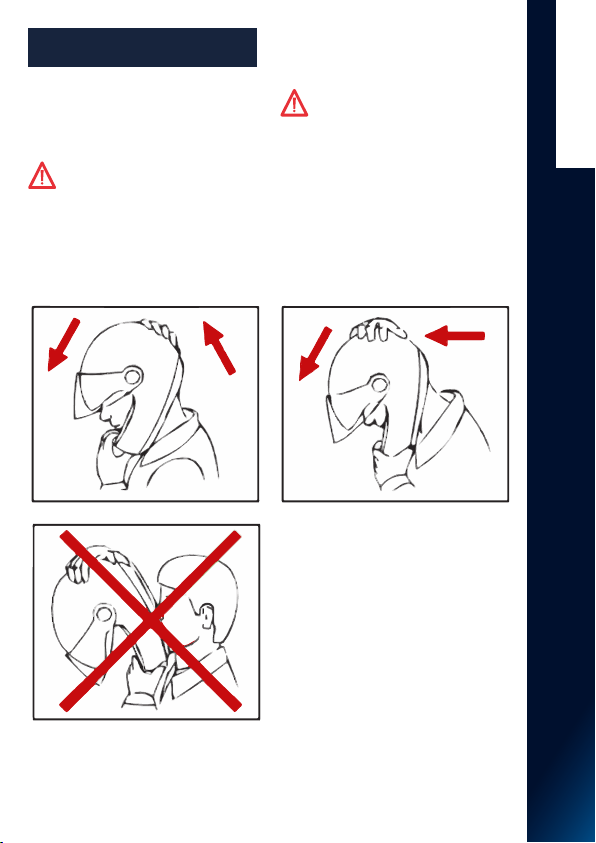
TAKING OFF THE HELMET
- With the helmet on and the strap securely
fastened, try to take the helmet off as
shown in Fig. A. In case of accident the
different forces at stake and their various
directions may result in helmet rotations or
they may even cause the helmet to slip off
if it is not securely fastened.
- The helmet should not rotate nor move
on the head and should not slide off.
Should the contrary happen, adjust strap
length or change helmet size. Repeat test.
RETENTION SYSTEM
- The retention system (strap) is factory-
adjusted at a standard length. Before use,
check that it is correctly pre-adjusted.
- Make sure the strap is properly fastened
and tightened so as to keep the helmet
firmly in place. Anyway, before riding,
make sure that the strap is well fastened
under the chin, as close as possible to the
throat, but without being uncomfortable.
- The correct strap tension should allow
normal breathing and swallowing, but
without leaving the space of a finger
between strap and throat.
Attention: the button which may be
present on the strap only prevents
its end from flapping once the strap has
been fastened properly.
I N S T R U C T I O N S F O R U S E

3
FIG. A
ENGLISH
MAINTENANCE
AND CLEANING
- Damage resulting from accidental
fall may not be visible; helmets, which
received violent impacts, are to be
replaced.
Attention: the helmet can be
seriously damaged by some common
substances with- out the damage being
visible. To clean the helmet, use only
lukewarm water and mild soap; dry at
room temperature, away from direct
sunlight and/or heat sources.
Attention: never use gasoline,
thinner, benzol, solvents or other
chemicals as they may irreparably
damage the helmet irreparably damage
the helmet.
I N S T R U C T I O N S F O R U S E

4
0
Fig. 1
I N S T R U C T I O N S F O R U S E
The peak can be adjusted in different
positions by turning it upwards or
downwards (Fig. 1). It also is equipped with
a peak extension that can be adjusted in
three different positions. (Fig. 2A).
WARNING: When riding on the
road, the peak must be adjusted to
the highest position “0” (Fig. 1) and the
peak extension must be at the minimum
extension position “0” (Fig. 2A).
PEAK AND PEAK EXTENSION
ENGLISH
“D-RINGS” RETENTION SYSTEM
Your new helmet is equipped with the D-ring
retention system.
To ensure maximum protection and enjoy the
advantages of the D-ring retention system,
carefully read and follow the instructions on
this label.
In order to prevent improper use of the helmet
and, in particular, to prevent it from being
incorrectly fastened, the ECE 22-05 approval
standard requires that the helmet be put on and
removed without having to unthread the band
completely from the rings.
For this reason, this retention system, which
is only efficient when the band is threaded
correctly in the rings as illustrated in Fig. 1, is
supplied pre-fastened and is conceived in such
a way as to limit closing and opening to simple
adjustments of the tightness of the band.
THEREFORE IT IS SUPPLIED WITH:
- a band end fitted with the male side of a snap
button that prevents the retention system from
opening completely, and once the tightness is
adjusted, prevents it from fluttering when it is
fastened to the female side;
- a red quick release flap that facilitates the
loosening of the retention system.
To put on the helmet:
- Unhook the snap button by pulling on the band
end (see Fig. 2).
- Pull the red quick release flap until the band is
loosened completely without unthreading it from
the rings (see Fig. 3).
- With the help of your thumbs, bring the
pre-fastened chin band towards the forward part
of the helmet so that it does not get in the way
of your face while the helmet is being put on.
- Put on the helmet ensuring that it is the correct
size for you (see the attached instruction leaflet).
- Pull the band end (see Fig. 1) until you feel the
band tightly pressed against your jaw.
- Refasten the snap button on the band end
(see Fig. 2).
- Now try to remove the helmet by taking hold
of it by the rear edge and rotating it forward. The
helmet should remain well fitted on your head
(see the attached instructions). If the helmet
tends to come off your head, pull the chin band
again until the correct pressure is reached and
try again.
TO REMOVE THE HELMET:
- Unhook the snap button by pulling the band
end (see Fig. 2).
- Pull the red quick release flap until the band is
loosened completely without unthreading it from
the rings (see Fig. 3).
- With the help of your thumbs, bring the pre-
fastened chin band towards the front part of the
helmet so that is does not get in the way of your
face and remove the helmet.
WARNING: THE BAND MUST NEVER BE
UNTHREADED FROM THE RINGS.
THE SNAP BUTTON DOES NOT HAVE THE
FUNCTION OF RETAINING THE HELMET.
NEVER PULL THE RED FLAP WHILE DRIVING.
We suggest that you periodically clean the
D-ring release with lukewarm water and neutral
soap.
Do not use solvents. Do not grease.
Tampering with or unforeseen events that may
compromise the working order of the retention
system should not be ruled out. In this event
discontinue use of the helmet.

5
Fig. 3
0
Fig. 2 A Fig. 2 B
I N S T R U C T I O N S F O R U S E
1. PEAK ADJUSTMENT
1.1. Loosen the tightness of the upper central
threaded cover plate “A” by rotating it counter-
clockwise (Fig. 3).
1.2. Rotate the peak on the side cover plates
“B” to adjust it to the desired posi- tion, which
is the highest one when riding on the road (see
position “0” in Fig. 1).
1.3. Lock the peak in the desired position by
tightening the upper central threaded cover
plate “A”; check that the side cover plates “B”
are not loose (Fig. 3).
2. PEAK EXTENSION
ADJUSTMENT
2.1. Completely unscrew the internal screws
located at both ends of the peak extension
(Fig. 2B).
2.2. Remove the extension from the peak;
then put it back in one of the three possible
positions, which when riding on the road is
the one farthest back (see position “0” in Fig.
2A), by inserting its side pins in the specific
holes at the two ends of the peak.
2.3. Tighten the internal screws while
checking that the peak extension is posi-
tioned symmetrically on the peak.
3. PEAK DISASSEMBLY
3.1. Completely unscrew the threaded side
cover plates “B” by rotating them counter-
clockwise so that the side ends of the peak
detach from the helmet shell (Fig. 3). Pay
attention not to lose the two air intakes
placed between the peak and the shell
(Fig. 2B).
3.2. Completely unscrew the upper central
threaded cover plate “A” by rotating it
counter-clockwise (Fig. 3). Remove the peak
from the helmet, paying particular attention
not to lose the trim of the upper central
threaded cover plate “A” placed between
the peak and the shell (Fig. 2B).
4. PEAK ASSEMBLY
Check that the air intakes are properly
hooked to the peak as they were originally
(Fig. 2B).
4.1. Place the trim of the upper central
cover plate “A” in line with the threaded hole
and place the peak on the shell. Insert the
upper central threaded cover plate “A” into
the hole and fasten by rotating it clockwise
without tightening it completely (Fig. 3).
4.2. Insert the left side cover plate “B” into
the relevant seat on the shell and tighten
it completely (Fig. 3). Repeat the same
operation on the other side of the helmet.
4.3. Complete the adjustment of the
position of the peak and its extension as
pre- viously described (see steps 1.2., 1.3.
and 2.).
WARNING: Check that the cover
plates, internal trim and air intakes, which
are interposed between the peak and the
helmet shell, keep the peak steady in the
desired position.
- Do not use the helmet if the peak and
peak extension have not been assem- bled
and adjusted properly.
- Do not install the peak without the
internal trim of the cover plates and air
intakes.
- In case of malfunctioning or damages,
please contact an authorized SHARK
dealer.
ENGLISH

6
Fig. 6
Fig. 4
Fig. 5
A B
Fig. 7
REMOVABLE INNER
COMFORT PADDING
The removable comfort padding consists
of a liner, pads of the side cheek pads
(right and left) and covering straps, all
completely removable and washable.
The cheek pads are also characterised by
removable inner expanding foam padding.
5. CHEEK PAD DISASSEMBLY
5.1. Unfasten the chin strap (see
instructions).
5.2. Gently pull the red strap in the front
area of the pad of the left cheek pad to
release the safety lever on its back (Fig. 4).
R E M O VA B L E I N N E R CO M FO RT PA D D I N G
ENGLISH
5.3. Hold the front part of the pad of the
left cheek pad and turn it upwards to
un- hook the front and upper hooks on
its back (Fig. 5).
5.4. Pull the back of the pad of the left
cheek pad towards the inside of the
helmet to undo the snap fastener on its
back (Fig. 6).
5.5. Pull brackets “A” and “B” of the pad
of the left cheek pad upwards to unhook
them from the corresponding plates
between the outer shell and polystyrene
cheek pad (Fig. 7).
5.6. Completely remove the pad of the left
cheek pad from the helmet.
5.7. Repeat these steps with the right
cheek pad.
Note: Do not remove the polystyrene
cheek pads from the helmet shell.

7
A
A
B
CD
Fig. 8
Fig. 9
ENGLISH
6. DISASSEMBLY OF THE INNER EXPANDING
FOAM PADDING OF THE CHEEK PADS
To make it easier to wash the inner
comfort padding components, the cheek
pads of the helmet are fitted with inner
expanding foam padding that can be
removed from the fabric lining. To remove
the padding, proceed as follows after
removing the cheek pads from the helmet
(see instructions above).
6.1. Unhook the three eyelets of the rear
frame of the left cheek pad next to the
two hooks “A” (top and front) and snap
button “D” (rear) on its back, respectively
(Fig. 8).
6.2. Take the top “B” and bottom “C” flaps
of the frame out of the respective loops on
the back of the frame (Fig. 8).
6.3. Gently remove the inner expanding
foam padding from the fabric lining of the
cheek pad (Fig. 9).
6.4. Repeat these steps with the right
cheek pad.

8
Fig. 10 A
Fig. 11
Fig. 10 B
L=Le
R=Right
Fig. 12
ENGLISH
7.DISASSEMBLY OF THE CHIN
STRAP COVERING
To remove the chin strap covering from
the strap, proceed as follows after
removing the cheek pads from the helmet
(see instructions above).
7.1. Pull the left covering strap in line with
the “hook and loop fastener” to separate
it from the chin strap band and then take
it off (Fig. 10A).
7.2. Repeat these steps with the right
covering strap.
8. LINER DISASSEMBLY
8.1. Pull the back of the comfort padding
towards the inside of the helmet to
unhook the two side buttons on its back
from their seats on the rear support fixed
to the polystyrene inner shell (Fig. 11).
8.2. Unhook the left front flap from the
support fixed to the inner shell below
the trim of the upper edge of the shell
by slightly pulling the comfort padding
towards the inside of the helmet (Fig.
12). Repeat the same steps for the central
front and right front flaps.
8.3. Completely remove the comfort
padding from the helmet.

9
Fig. 13
Fig. 14
ENGLISH
9. MONTAGE DE LA COIFFE
9.1. Properly insert the comfort padding
into the helmet.
9.2. Slip the left front flap of the liner into
its seat by slightly deforming the upper
shell sealing edge (Fig. 13). Repeat the
same steps for the central front and right
front flaps.
9.3. Correctly turn up the shell sealing
edge and press downwards in line with
the three front flaps (left, central and
right) until they are fully fastened to the
support. Make sure that the front helmet
area is as shown in Fig. 14.
9.4. Fasten the two side buttons on the
back of the rear part of the comfort
padding to the corresponding seats on the
rear support fixed to the polystyrene inner
shell (Fig. 11).
9.5. Spread out the inner comfort padding
and make it stick to the inner shell by
applying pressure first in the upper zone,
so that the hook and loop fastener strap on
the top of the inside of the shell grips, and
then along the circumference.
10. ASSEMBLY OF THE CHIN
STRAP COVERING
The right and left chin strap covering are
different from each other (Fig. 10B).
10.1. After identifying the left covering
strap, insert the release mechanism of the
chin strap inside of it in line with the free
end of the “hook and loop fastener” until it
comes completely out from the central slot.
Press the free end of the strap over the chin
strap band in line with the “hook and loop
fastener” and pull the strap to stretch it out
completely (Fig. 10A).
10.2. Repeat these steps with the right
covering strap.
10.3. Make sure the straps are secured by
gently pulling them towards the inside of
the helmet.
10.4. If the release mechanism is the D-Ring
type, check that the anti-fluttering snap
button on the left strap only is correctly
placed past the two D-rings (Fig. 10B).

10 Fig. 15
11.ASSEMBLY OF THE INNER
EXPANDING FOAM PADDING
OF THE CHEEK PADS
11.1. Gently put the inner expanding foam
padding inside the fabric lining of the left
cheek pad (Fig. 9). Carefully spread out
the padding while checking that there are
no wrinkles in the cheek pad fabric lining.
11.2. Insert the upper “B” and lower “C”
flaps of the frame in their loops on the
back of the frame (Fig. 8).
11.3. Hook the three eyelets of the rear
frame of the left cheek pad near the two
“A” hooks (top and front) and snap button
“D” (rear) on the back (Fig. 8).
11.4. Repeat these steps with the right
cheek pad.
WARNING: the rear eyelet with its snap
button “D” has a shape different from
that of the front and top eyelets and of
the corresponding hooks “A”.
12. CHEEK PAD ASSEMBLY
12.1. Take the pad of the left cheek pad
and check that the safety lever on the
back is in the opening position (Fig. 15).
12.2. Put the left cheek pad inside the
helmet and insert the rear bracket “B”
in the corresponding plate between the
outer shell and polystyrene cheek pad by
pressing until it is fastened (Fig. 7).
12.3. Insert the chin strap in the
passageway of the cheek pad padding and
press near the rear snap fastener placed on
the back to fasten it to the relevant seat on
the polystyrene cheek pad (Fig. 6).
12.4. Press the pad of the left cheek pad
against the polystyrene cheek pad and at
the same time turn it inwards to fasten the
front and top hooks on its back. (Fig. 5).
12.5. Press the safety lever upwards in line
with the fastening area of the red strap to
turn it towards the cheek pad padding until
it reaches its closing position. (Fig. 4).
12.6. Check that the fastener and hooks
are firmly fastened by slightly pulling the
pad of the cheek pad towards the inside
of the helmet, then check that it re- mains
adherent to the polystyrene cheek pad.
12.7. Insert front bracket “A” in the
corresponding plate between the outer
shell and polystyrene cheek pad, then
press it until it becomes fastened (Fig. 7).
Place the front red strap against the inner
surface of the chin guard.
12.8. Repeat these steps with the right
cheek pad.
WARNING: the buttons are not hooked
until a click is heard. Check that the strap
comes out properly from the cheek pad
padding.
WARNING: If your helmet is
equipped with the double D-Ring
retention system, pull it down as indicated
in the attached double D-Ring label.
- Remove the inner comfort padding only
when cleaning or washing is required.
- Never use the helmet if all parts of
the inner comfort padding have not been
correctly and completely reassembled.
- Delicately hand-wash in lukewarm water
(max. 30° C) and neutral soap.
- Rinse with cold water and allow drying
at room temperature, away from direct
sunlight.
ENGLISH

11
Fig. 16
A
B
Fig. 17
- Never machine-wash the inner comfort
padding.
- The inner polystyrene is an easily
deformable material. It is apt to change
or get partially destroyed to help absorb
shocks.
- Do not modify or alter the helmet’s
internal polystyrene components in any
way.
- Clean the inner polystyrene components
with a damp cloth only and allow it to dry
at room temperature away from direct
sunlight.
- Never use tools or equipment of any sort
to carry out the steps described above.
13. CREATING SPACE
FOR GLASSES
13.1. Remove the left cheek pad from the
helmet (see instructions above).
13.2. Unhook the rear frame eyelet of the
cheek pad in line with the top hook “A”
shown on its back (Fig. 16).
13.3. Take the top flap “B” of the frame
out of the loop on the back of the frame
(Fig. 16).
E Y E W E A R A D A P T I V E
13.4. Gently remove the inner expanding
foam padding from the fabric lining of the
cheek pad (Fig. 17).
13.5. Remove the upper part of the inner
pre-punched padding (Fig. 17), then
correctly put back the remaining padding
part in the cheek pad.
NOTE: it is recommended to keep the
removed padding for any subsequent
reuse.
13.6. Put the top flap “B” of the frame
back in the loop on the back of the cheek
pad and refasten the eyelet in line with
the top hook “A” on the back (Fig. 16).
13.7. Refit the complete cheek pad on
the helmet (see instructions above).
13.8. Repeat these steps with the right
cheek pad.
14. REMOVING SPACE
FOR GLASSES
14.1. Remove the left cheek pad from the
helmet (see instructions above).
14.2. Unhook the rear frame eyelet of the
cheek pad in line with the top hook “A”
shown on its back (Fig. 16).
14.3. Take the top flap “B” of the frame
out of the loop on the back of the frame
(Fig. 16).
14.4. Properly insert part of the
previously removed padding in the fabric
lining of the cheek pad (Fig. 17).
14.5. Put the top flap “B” of the frame
back in the loop on the back of the cheek
pad and refasten the eyelet in line with
the top hook “A” on the back (Fig. 16).
14.6. Refit the complete cheek pad on
the helmet (see instructions above).
14.7. Repeat these steps with the right
cheek pad.
ENGLISH

12
Fig. 18
Fig. 19
NOLAN EMERGENCY RELEASE SYSTEM
The Nolan Emergency Release System (NERS) allows the rescue personnel to remove the
pads of the cheek pads from the helmet while it is still on the rider’s head.
To remove the pad of the left cheek pad from the helmet, unfasten the chin strap and then
pull the red strap in the front area of the pad as shown in Fig. 18.
The safety lever placed on the back of the pad of the cheek pad will first release and
then, while continuing to pull the red strap, the pad will release from the polystyrene and
gradually turn toward the outside of the helmet, leaving its side area free.
Repeat the same step on the right side of the helmet, which can then be more easily
removed from the rider’s head.
N O L A N E M E R G E N C Y R E L E A S E S Y S T E M
ENGLISH
WARNING: Never pull the red straps
of the Nolan Emergency Release
System (NERS) while riding.
- Always check that the cheek pads are
properly installed. After using the Nolan
Emergency Release System (NERS), check
that the cheek pads are not dam- aged
and reassemble them following the
instructions above.
- Do not use the Nolan Emergency Release
System (NERS) for the routine cheek pad
maintenance and cleaning operations.
- Do not take the stickers shown in
Fig. 19 off the helmet as they could
provide useful information to rescue
personnel.
- Should the Nolan Emergency Release
System (NERS) fail or be damaged, please
refer to an SHARK authorized dealer.
- Use the Nolan Emergency Release
System (NERS) for providing aid only if you
have proven expertise and qualifications
in the field. If in doubt, call the
appropriate emergency personnel.

13
A
B B
Fig. 20
Fig. 21
CD
Fig. 22
ENGLISH
“CAMEL BAG” ARRANGEMENT
FOR THE HYDRATION SYSTEM
The helmet is designed to facilitate
installation of a hydration system (not
supplied) and fastening its hose. It includes
(Fig. 20):
- a side hose clip “A”, on the “READY FOR
CAMEL BAG” strap, useful for fastening
the hydration system hose;
- a deformable seat “B” on the lower edge
of the inner chin guard for positioning the
end of the hose with the suction valve near
the mouth.
The “READY FOR CAMEL BAG” strap and
the deformable seat “B” are on both sides
of the helmet.
If you do not use a hydration system,
we recommend removing hose clip “A”
(see instructions below) and positioning
the “READY FOR CAMEL BAG” straps
behind the pads of the removable cheek
pads. To do so, pull the bottom part of
the pad of the left cheek pad upwards
to release brackets “C” and “D” from the
corresponding plates between the outer
shell and the polystyrene cheek pad (Fig.
21).
Then place the “CAMEL BAG” strap against
the polystyrene cheek pad (Fig. 22).
Afterwards insert brackets “C” and “D”
in the corresponding plates between the
outer shell and the polystyrene cheek
pad, then press until they are fastened
(Fig. 21).
Repeat these steps with the right cheek
pad.

14 Fig. 23
ENGLISH
15. HYDRATION SYSTEM HOSE
ASSEMBLY
To fasten the hydration system hose,
slightly buckle the free part of side hose
clip “A” and put the hose inside it. Then
buckle seat “B” of the inner chin guard and
insert the initial part of the hose with the
suction valve inside it. Adjust the length
of the hose by sliding it into housings “A”
and “B” and continue to assemble the
hydration system following the relevant
instructions and recommendations
provided by its manufacturer.
16. HYDRATION SYSTEM HOSE
DISASSEMBLY
To disassemble the hydration system hose,
slip off its initial part by buckling seat “B”
of the inner chin guard. Then remove the
hose from side hose clip “A” while buckling
it slightly.
17. HOSE CLIP DISASSEMBLY
To remove fastening side hose clip “A”
from the “READY FOR CAMEL BAG” strap,
buckle its side parts and remove them
from the strap (Fig. 23).
18. HOSE CLIP ASSEMBLY
To assemble side hose clip “A” on the
“READY FOR CAMEL BAG” strap, insert
first one and then the other deformable
side part of the clip under the “READY
FOR CAMEL BAG” strap until they are
completely fastened while taking care to
position the free and deformable fastening
part of the hose facing upward (Fig. 20).
WARNING: Do not use for any reason
the “READY FOR CAMEL BAG” straps
and/or the hose clip for any purpose other
than those described above.
- Always check that the side hose clip
does not become entangled with clothing
or obstructs movement of the head
and helmet, which must always be free.
Verify this by wearing all your clothing,
including any neck and/or body braces
and protectors normally used in off-road
sports. If necessary, remove the side hose
clip from the helmet.
- Remove the side hose clip and fold back
the “READY FOR CAMEL BAG” strap if a
hydration system is not used.
- Fasten the side hose clip only to the
“READY FOR CAMEL BAG” strap.
- Do not fasten the side hose clip to the
cheek pads and/or removable padding.
- Do not modify or tamper with the helmet
components to install the hydration
system. Check that the hydration system
hose is compatible with the hose clip and
deformable seat of the chin guard.
- In case of doubt, malfunctioning or
damage, please contact an SHARK
authorized dealer.

15
Fig. 24
ENGLISH
VENTILATION SYSTEM
The ventilation system of the helmet (Fig.
24) consists of:
UPPER AIR INTAKES:
the two openings located under the peak
capture and channel the air, directing it
dispersion-free in the upper area of the
rider’s head.
FRONT AIR INTAKES:
also with the contribution of the side
conveyors, two openings located under
the peak capture and channel the air,
directing it dispersion-free in the front
area of the rider’s head. Another two
openings are in the front area, near the
sealing edge of the window opening.
CHIN GUARD AIR INTAKE:
provides ventilation in the mouth area
while filtering its content.
AIR EXTRACTORS:
located on the upper rear part of the
helmet, in line with the rear base edge and
on the sides of the helmet so that warm
and stale air can flow out, thus ensuring
optimum comfort inside the helmet.

Fig. 25
ENGLISH
CHIN GUARD AIR INTAKE
FILTERS
The chin guard air intake is fitted with a fixed
external filter in metal mesh that allows easy
air intake while limiting the entry of insects or
small stones, and a second removable internal
filter assembled in the inner chin guard that
can be removed from its housing to increase
the flow rate of the air intake and/or to be
washed.
19. DISASSEMBLY OF
THE REMOVABLE INTERNAL
FILTER
To remove the removable internal filter, pry
its holding frame towards the inside of the
helmet near the upper right corner of the
frame. Unfasten the holding frame from the
deformable internal chin guard by slipping the
fastening flaps out of the slots on the internal
chin guard.
Completely remove the holding frame from
the chin guard and pull the filter out from its
housing in the internal chin guard.
Then reassemble the filter holding frame on
the internal chin guard by inserting, one by
one, the side and then upper fastening flaps
of the frame in the corresponding slots on
the internal chin guard applying light pressure
above (Fig. 25).
20. ASSEMBLY OF THE
REMOVABLE INTERNAL FILTER
To replace the removable internal filter,
remove its holding frame as explained above,
insert it and place it properly in its housing in
the chin guard. Then reassemble the holding
frame as explained above (Fig. 25).
WARNING: If you wish to use the
helmet without the removable internal
filter, it is recom- mended to always install
the filter holding frame.

2
SÉCURITÉ ET INSTRUCTIONS
IMPORTANT
- Lisez ce manuel et tous les autres documents
inclus avant d’employer votre casque
parce qu’ils contiennent des informations
importantes qui vous aideront à employer
au mieux le casque, en toute sécurité et
simplicité.
- Conformez-vous scrupuleusement aux
indications, sous peine de réduire la protection
garantie par le casque et de compromettre
ainsi votre sécurité.
EMPLOI DU CASQUE
- Ce casque a été expressément conçu pour
l’emploi avec la moto et le cyclomoteur; il ne
doit pas etre utilisé pour d’autres usages (ou
emplois ou fins) puisque, dans de pareils cas, il
ne garantit pas la même protection.
- En cas d’accident, le casque est un élément
de protection qui permet de limiter les
lésions et les dommages à la tête. Malgré
cela, il n’est pas en gré tout seul d’éliminer les
risques de blessures graves et/ou mortelles,
qui dépendent des dynamiques différentes
spécifiques du choc, pour cette raison
conduisez avec prudence.
- Mettez toujours le casque bien fixé pour
conduire la moto, pour faire en sorte que sa
protection soit maximale.
- Ne portez jamais d’écharpes sous le système
de fixation ni n’importe quel type de couvre-
chef sous le casque.
- Le casque peut assourdir les bruits de la
circulation. En tous les cas, veillez toujours à
ce que vous puissiez bien entendre les bruits
nécessaires comme les klaxons et les sirènes
d’alerte.
- Gardez toujours le casque loin de sources
de chaleur, comme par exemple le pot
d’échappement, le logement du coffret ou
l’habitacle d’un moyen de transport.
- Ne modifiez et/ou altérez pas le casque
(même si seulement en partie) pour aucune
raison. Ne montez que les accessoires et/
ou rechanges originaux pour votre modèle
spécifique de casque.
- Les dommages au casque qui sont causés par
des chutes accidentelles ne sont pas toujours
bien visibles, si le casque subit un choc violent
il doit être remplacé.
- En cas de doutes sur l’intégrité et sécurité
du casque, abstenez-vous de l’utiliser et
adressez-vous à un revendeur agrée pour le
faire examiner.
CHOIX DU CASQUE
TAILLE
- Pour trouver la bonne taille, mettez
plusieurs casques aux tailles différentes et
choisissez celui qui s’adapte le mieux à la
conformation de votre tête. Ce casque doit
être parfaitement stable dès que vous le
mettez et convenablement attaché de façon à
garantir un confort optimal.
- Un casque trop grand peut descendre
jusqu’à couvrir les yeux, ou il peut tourner
latéralement pendant la conduite.
- Gardez-le sur la tête pendant quelques
minutes et vérifiez qu’il n’y ait aucune zone
de pression localisée, qui à la longue peut
provoquer des douleurs ou des maux de tête.
ENLÈVEMENT
- Après avoir mis le casque et après avoir
bien attaché la jugulaire, essayez d’enlever
votre casque comme le montre la figure
(Fig. A). En cas d’accident, plusieurs forces ainsi
que les directions de ces forces peuvent en
effet entraîner des rotations du casque, voire
l’enlèvement involontaire de celui-ci de votre
tête si vous ne l’avez pas attaché parfaitement.
- Le casque ne doit pas tourner, bouger
librement sur la tête ou s’enlever. En cas
contraire, réglez la longueur de la jugulaire
ou changez la taille du casque. Répétez à
nouveau l’essai.
SYSTÈME DE FIXATION
- Le système de fixation (jugulaire) est réglé
en série avec une longueur standard; avant
de l’utiliser veillez à ce que le pré-réglage
soit correct.
- Assurez-vous toujours que la jugulaire
soit bien fixée et étroite de façon à tenir
le casque bien immobile sur votre tête. En
tout cas, avant de partir, assurez-vous que la
jugulaire soit bien fixée sous le menton, le plus
arrière possible vers la gorge, mais sans être
inconfortable.
- La tension correcte de la jugulaire doit vous
permettre une respiration et une déglutition
normale, mais sans réussir à faire passer un
doigt entre la jugulaire et la gorge.
FRANÇAIS

3
FIG. A
ATTENTION: le bouton éventuellement
présent sur la jugulaire n’a que la
fonction d’empêcher le flottement de la
partie terminale de la jugulaire même, après
l’avoir fixée correctement.
ENTRETIEN ET NETTOYAGE
- Les dommages au casque qui sont causés par
des chutes accidentelles ne sont pas toujours
bien visibles, si le casque subit un choc violent
il doit être remplacé.
ATTENTION: le casque peut être
sérieusement endommagé au contact
de certaines substances communes sans que
le dommage ne soit visible. Pour le nettoyage
du casque, utiliser uniquement de l’eau tiède
et du savon neutre ; laisser sécher à tempé-
rature ambiante, à l’abri du soleil et/ou de
toute source de chaleur.
ATTENTION: ne jamais utiliser
d’essence, de diluant, de benzol, de
solvants ou toutes autres substances
chimiques car elles peuvent endommager le
casque de façon irréversible endommager
irrémédiablement le casque.
FRANÇAIS

4
0
Fig. 1
FRANÇAIS
I N S T R U C T I O N S D ’ U T I L I S A T I O N
La visière peut être réglée dans plusieurs
positions en la faisant pivoter vers le haut ou
vers le bas (Fig. 1). Le casque est également
équipé d’une casquette qui peut être réglée
dans trois positions différentes. (Fig. 2A).
ATTENTION: Pour l’utilisation sur
route, la visière doit être réglée dans la
position « 0 » de hauteur maximale (Fig. 1) et
la casquette doit se trouver dans la position
« 0 » d’extension minimale (Fig. 2A).
“D-RINGS” SYSTEME
DE RETENTION
Votre nouveau casque est doté du système
de fixation par anneaux, D-Rings Retention
System. Pour obtenir la plus grande protection et
apprécier les avantages du système de fixation
«D-Rings», lire attentivement les instructions de
cette fiche et s’y conformer.
Le standard d’homologation ECE 22-05 permet
de mettre et d’ôter le casque sans devoir retirer
tout le ruban des anneaux, ce qui prévient
l’usage impropre du casque et évite notamment
que celui-ci ne soit mal attaché. Ce système de
fixation, qui n’est efficace que lorsque le ruban
est correctement introduit dans les anneaux (voir
Fig. 1), est donc fourni pré-bouclé. Il a par ailleurs
été conçu de sorte à limiter les opérations de
fermeture et d’ouverture à de simples réglages
de la tension du ruban.
Il est donc équipé d’:
- un ruban dont l’extrémité de la partie mâle
présente un bouton automatique qui évite non
seulement l’ouverture complète du système de
fixation mais aussi son flottement, après réglage
de la tension, lors de sa fixation sur la partie
femelle;
- une languette rouge d’ouverture rapide qui
facilite l’opération de desserrage du système de
fixation lui-même.
POUR METTRE LE CASQUE :
- Débloquer le bouton automatique en tirant sur
l’extrémité du ruban (voir Fig. 2).
- Tirer la languette rouge d’ouverture rapide
jusqu’à desserrer complètement le ruban sans le
faire sortir des anneaux (voir Fig. 3).
- À l’aide des pouces, amener la jugulaire pré-
bouclée vers l’avant du casque, au moment
d’enfiler ce dernier, de manière à ce qu’elle
n’interfère pas avec le visage.
- S’assurer que la taille du casque est la bonne
au moment de le mettre (voir le manuel
d’instructions en annexe).
- Tirer l’extrémité du ruban (voir Fig. 1) jusqu’à
ce que la jugulaire s’appuie contre la mâchoire.
- Bloquer de nouveau le bouton automatique de
l’extrémité du ruban (voir Fig. 2).
- Essayer à ce point de retirer le casque en
le saisissant par le bord postérieur et en le
faisant tourner vers l’avant. Le casque ne doit
pas bouger (voir le manuel d’instructions en
annexe). Si le casque est lâche, tirer de nouveau
la jugulaire jusqu’à obtenir la bonne pression et
répéter l’essai.
POUR ÔTER LE CASQUE :
- Débloquer le bouton automatique en tirant sur
l’extrémité du ruban (voir Fig. 2).
- Tirer la languette rouge d’ouverture rapide
jusqu’à desserrer complètement le ruban sans le
faire sortir des anneaux (voir Fig. 3).
- À l’aide des pouces, amener la jugulaire pré-
bouclée vers l’avant du casque de manière à
ce qu’elle n’interfère pas avec le visage et ôter
le casque.
ATTENTION: LE RUBAN NE DOIT
JAMAIS SORTIR ENTIÈREMENT DES
ANNEAUX. LA FONCTION DU BOUTON
AUTOMATIQUE N’EST PAS CELLE DE FIXER LE
CASQUE. NE JAMAIS TIRER LA LANGUETTE
ROUGE PENDANT LA CONDUITE. Nous
conseillons un nettoyage périodique du système
de décrochage « D-Rings » avec de l’eau tiède et
du savon neutre. Ne pas utiliser de solvants. Ne
pas lubrifier. Ne pas utiliser le casque en cas
de manipulations ou d’évènements particuliers
pouvant compromettre le bon fonctionnement
du système de fixation.
VISIÈRE ET CASQUETTE

5
Fig. 3
0
Fig. 2 A Fig. 2 B
FRANÇAIS
I N S T R U C T I O N S D ’ U T I L I S A T I O N
1. RÉGLAGE DE LA VISIÈRE
1.1. Desserrer le cliquet fileté central supérieur «
A » en le faisant tourner dans le sens inverse des
aiguilles d’une montre (Fig. 3).
1.2. Tourner la visière autour des cliquets latéraux
« B » pour la régler dans la position souhaitée,
c’est-à-dire la position de hauteur maximale pour
l’utilisation sur route (voir Position « 0 » sur la
Fig. 1).
1.3. Bloquer la visière dans la position souhaitée
en serrant le cliquet fileté central supérieur « A » ;
contrôler que les cliquets latéraux « B » ne se sont
pas desserrés (Fig. 3).
2. RÉGLAGE DE LA CASQUETTE
2.1. Dévisser complètement les vis internes
situées aux deux extrémités de la casquette de la
visière (Fig. 2B).
2.2. Retirer la casquette de la visière ;
la replacer ensuite dans l’une des trois
positions possibles, qui pour l’utilisation sur route
correspond à la position la plus reculée (voir
position « 0 » sur la Fig. 2A), en introduisant ses
axes latéraux dans les trous percés aux deux
extrémités de la visière.
2.3. Visser les vis internes en veillant à ce que
la casquette soit placée symétriquement sur la
visière.
3. DÉMONTAGE DE LA VISIÈRE
3.1. Dévisser complètement les cliquets latéraux
filetés « B » en les faisant tourner dans le sens
inverse des aiguilles d’une montre afin que les
extrémités latérales de la visière se détachent
de la calotte du casque (Fig. 3). Veiller à ne pas
perdre les deux convoyeurs d’air situés entre la
visière et la calotte (Fig. 2B).
3.2. Dévisser complètement le cliquet fileté
central supérieur « A » en le faisant tourner dans
le sens inverse des aiguilles d’une montre (Fig.
3). Décrocher ensuite la visière du casque, en
veillant à ne pas perdre le joint du cliquet fileté
central supérieur « A » situé entre la visière et la
calotte (Fig. 2B).
4. MONTAGE DE LA VISIÈRE
S’assurer que les convoyeurs d’air sont bien
accrochés à la visière comme à l’origine
(Fig. 2B).
4.1. Placer le joint du cliquet central supérieur
« A » à la hauteur du trou fileté et appuyer
la visière sur la calotte ; introduire ensuite le
cliquet fileté central supérieur « A » dans le
trou et le visser en le faisant tourner dans le
sens des aiguilles d’une montre sans le serrer
complètement (Fig. 3).
4.2. Insérer le cliquet latéral de gauche « B »
dans le logement correspondant sur la calotte et
le visser complètement (Fig. 3). Répéter ensuite
l’opération sur l’autre côté du casque.
4.3. Achever le réglage de la position de la
visière et de sa casquette comme expliqué dans
les instructions précédentes (voir les opérations
1.2.,1.3. et 2.).
ATTENTION: S’assurer que les cliquets,
le joint intérieur et les convoyeurs,
interposés entre la visière et la calotte du
casque, permettent à la visière de rester stable
dans la position souhaitée.
N’utiliser le casque qu’après avoir monté et
réglé correctement la visière et la casquette.
Ne pas monter la visière sans le joint intérieur
des cliquets et les convoyeurs.
En cas de défauts de fonctionnement ou de
dommages, s’adresser à un revendeur agréé
SHARK.
Table of contents
Other Shark Motorcycle Accessories manuals

Shark
Shark Vantime User manual

Shark
Shark RIDILL User manual

Shark
Shark CITYCRUISER User manual

Shark
Shark Spartan Carbon User manual

Shark
Shark Nano User manual

Shark
Shark D-SKWAL 3 User manual

Shark
Shark RSF 2 RACE User manual

Shark
Shark SKWAL 2 User manual

Shark
Shark SX 2 User manual

Shark
Shark SPARTAN RS User manual