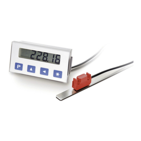
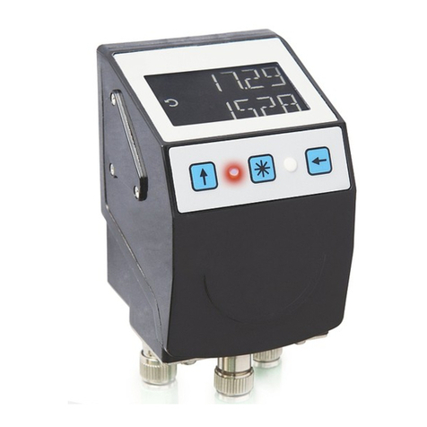
Siko AP10S User manual

110/20
AP10S
Absolute / Electronic Position Indicator with
plug connector for magnetic sensor and
interface
User manual

AP10S Date: 12.05.2020 Art. No. 90304 Mod. status 110/20 Page 2 of 44
Table of contents
1General Information .................................................................................................. 5
1.1 Documentation ........................................................................................................5
1.2 Definitions ..............................................................................................................5
1.3 Intended use ...........................................................................................................5
1.4 Switching on the operating voltage.............................................................................6
2Display and control elements...................................................................................... 6
2.1 LCD - Anzeige ..........................................................................................................6
2.1.1 Extended display range ..........................................................................................7
2.2 LED display..............................................................................................................7
2.2.1 Device status........................................................................................................7
2.3 Control keys.............................................................................................................7
2.3.1 Key lock and enable time .......................................................................................8
3Functional Description ............................................................................................... 8
3.1 Operating modes ......................................................................................................8
3.1.1 Absolute position operating mode ...........................................................................8
3.1.1.1 Positioning.......................................................................................................8
3.1.1.2 Loop positioning .............................................................................................10
3.1.1.3 ControlWord in Absolute Position operating mode ................................................10
3.1.1.4 StatusWord in Absolute Position operating mode .................................................11
3.1.2 Alpha-numeric display operating mode...................................................................12
3.1.2.1 ControlWord: Alpha-numeric display ...................................................................13
3.1.2.2 StatusWord: Alpha-numeric display ....................................................................13
3.2 Battery buffering....................................................................................................14
3.3 Parameterization of the position indicator .................................................................14
3.3.1 Manual parameterization......................................................................................15
3.3.1.1 Starting parameterization .................................................................................15
3.3.1.2 Value input.....................................................................................................15
3.3.1.3 Value selection................................................................................................15
3.3.1.4 Overview of the operating menu ........................................................................16
3.3.1.5 "Changeable parameters" menu .........................................................................16
3.3.1.6 Positioning.....................................................................................................17
3.3.1.7 Visualization...................................................................................................17
3.3.1.8 LED function...................................................................................................17
3.3.1.9 Device options ................................................................................................18
3.3.2 Parameterization via interface ..............................................................................18
3.4 Calibration ............................................................................................................18
3.5 Sensor ..................................................................................................................19
3.6 Alignment travel ....................................................................................................19
3.7 Additional functions ...............................................................................................19
3.7.1 Device data........................................................................................................19
3.7.2 Restore factory settings .......................................................................................20

AP10S Date: 12.05.2020 Art. No. 90304 Mod. status 110/20 Page 3 of 44
3.8 Warnings / Errors....................................................................................................20
3.8.1 Warnings ...........................................................................................................20
3.8.2 Errors ................................................................................................................20
3.8.3 Corrective actions ...............................................................................................21
4Parameter ............................................................................................................... 21
4.1 Process data ..........................................................................................................22
4.1.1 ControlWord .......................................................................................................22
4.1.2 StatusWord ........................................................................................................22
4.1.3 TargetValue........................................................................................................22
4.1.4 ActualValue........................................................................................................23
4.1.5 DisplayData........................................................................................................23
4.1.6 TargetValueLeft...................................................................................................24
4.2 Positioning............................................................................................................24
4.2.1 Resolution .........................................................................................................24
4.2.2 DecimalPlaces.....................................................................................................24
4.2.3 DisplayDivisor.....................................................................................................25
4.2.4 CountingDirection ...............................................................................................26
4.2.5 CalibrationValue..................................................................................................26
4.2.6 TargetWindow.....................................................................................................27
4.2.7 LoopType ...........................................................................................................27
4.2.8 LoopLength........................................................................................................28
4.3 Visualization..........................................................................................................28
4.3.1 DisplayOrientation ..............................................................................................28
4.4 LEDs .....................................................................................................................29
4.4.1 LEDMode............................................................................................................29
4.4.2 Led1GreenMode ..................................................................................................29
4.4.3 Led2GreenMode ..................................................................................................30
4.4.4 Led1RedMode .....................................................................................................30
4.4.5 Led2RedMode .....................................................................................................31
4.4.6 ActiveLedsFlashing..............................................................................................31
4.5 Device options .......................................................................................................32
4.5.1 SensorType.........................................................................................................32
4.5.2 KeyEnableTime....................................................................................................32
4.5.3 KeyCalibration ....................................................................................................33
4.5.4 KeyIncremental...................................................................................................33
4.5.5 OperatingMode ...................................................................................................34
4.5.6 PINChange .........................................................................................................34
4.5.7 LoadDefault........................................................................................................35
4.5.8 CODE .................................................................................................................35
5IO-Link ................................................................................................................... 35
5.1 Process data input / output .....................................................................................36
5.1.1 Process data in Absolute position operating mode ...................................................37
5.1.1.1 Process data output (master device) ..............................................................37

AP10S Date: 12.05.2020 Art. No. 90304 Mod. status 110/20 Page 4 of 44
5.1.1.2 Process data input (device master) ................................................................38
5.1.2 Process data in Alphanumeric display operating mode ..............................................38
5.1.2.1 Process data output (master device) ..............................................................39
5.1.2.2 Process data input (device master) ................................................................39
5.2 Directory of objects ................................................................................................40
5.2.1 IO-Link specific objects........................................................................................40
5.3 SystemCommands ...................................................................................................41
5.4 DeviceAccessLocks ..................................................................................................42
5.5 EventCodes............................................................................................................42
5.6 ErrorCodes .............................................................................................................42
6Block diagram ......................................................................................................... 43

General Information
AP10S Date: 12.05.2020 Art. No. 90304 Mod. status 110/20 Page 5 of 44
1General Information
1.1 Documentation
The following documents describe this product:
The data sheet describes the technical data, the dimensions, the pin assignment, the
accessories and the order key.
The installation instructions describe the mechanical and electrical installation with all
safety-relevant conditions and the associated technical specifications.
User manual for connecting the display to an IO-Link master and for commissioning.
IODD file (IO-Link Device Description); with the help of this file, the connection and
configuration with an IO-Link master is possible by means of commercially available IO-
Link masters and their configurators.
You can also download these documents at http://www.siko-global.com/p/ap10s.
1.2 Definitions
If not explicitly stated otherwise, decimal values are given as figures without an extension (e.
g. 1234), binary values are marked after the figure with a b (e. g. 1011b), hexadecimal values
with an h (e. g. 280h).
1.3 Intended use
Unless otherwise described, normal operation of the system with unchanged factory setting is
assumed for the further description of functions.
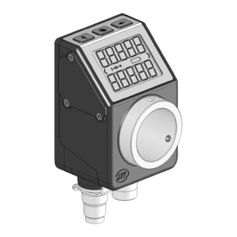
The present device is an absolute position indicator with integrated IO-Link interface and a
plug-in connection for MS500H magnetic sensor for direct linear distance measurement
(combined with MB500/1 magnetic tape) or a supported GS04 magnetic sensor for direct shaft
mounting. Indicators, control buttons and interface are only active with external power
supply. The sensor of measurement encoder works magnetically incrementally. Without an
external power supply, encoder changes are recorded with battery support. The status of the
replaceable battery is monitored. A volatile TargetValue can be displayed below the
ActualValue via the backlit two-line LC display A direction display (indicator) is displayed if
there is a deviation between the actual value and the target window (target value including
TargetWindow parameter). The arrow direction indicates in which direction the shaft must be
rotated to reach the target window. In addition, the position status of two two-color LEDs
(green and red) is displayed. Device malfunctions or inadmissible operating conditions are
displayed. Since both linear magnet sensors are used with the AP10S, a clockwise direction of
rotation must be equated with a positive travel path.

Display and control elements
AP10S Date: 12.05.2020 Art. No. 90304 Mod. status 110/20 Page 6 of 44
The buttons can be used to select various functions and to adapt the device parameters of the
application stored in non-volatile memory. The actual value can be queried via the interface,
the target value can be changed and all device parameters can be adjusted.
1.4 Switching on the operating voltage
The AP10S will be initialized after switching on the supply voltage. A system and display test
is executed during initialization, the LEDs are lighted consecutively and the parameters are
loaded from the non-volatile memory into the RAM of the controller.
At first use, the default values are used during initialization. After the return of the external
power supply or software reset (warm start), the AP10S works with the last saved parameters.
If no fault has been detected, the AP10S starts normal operation and can communicate with
an IO-Link Master.
2Display and control elements
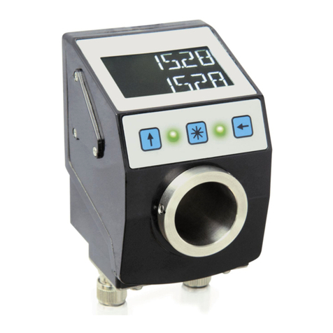
The position indicator has a two-line display with special characters and three control keys.
The actuator can be configured and controlled via the keys.
Two LEDs (LED1, LED2) serve for monitoring positioning.
Fig. 1: Display and control elements
2.1 LCD - Anzeige
The display range is limited to -199999 … 999999. Values outside this
range are displayed with "FULL".
When the operating voltage is applied, the actual value (absolute position value, ActualValue)
is displayed in the first line. If there is no valid target value, " --- " appears in the second
line. If a target value is declared valid by means of the control bit in the process data (see e.
g. bc09_TargetValueActive), this is displayed in the 2nd line. The values displayed are
determined by the operating mode.
Direction indicators (arrows) support positioning.
The battery symbol is shown with a critical or insufficient battery status. If battery
voltage drops to a critical value, the battery symbol on the display will flash. If it falls below
the minimum value, the symbol will glow permanently.
LED1
LED2
Display
Key configuration
Key calibration
Key incremental
measurement

Display and control elements
AP10S Date: 12.05.2020 Art. No. 90304 Mod. status 110/20 Page 7 of 44
With incremental measurement function activated, the incremental measurement symbol
is shown.
This is signaled in red letters in the event of a fault.
Fig. 2: Two-line 14 segment LCD display
2.1.1 Extended display range
Values up to -199999 can be displayed by means of the ControlWords (see
bc03_DisplayRange). If the relevant bit has been set and the value to be displayed is between
-199999 and -999999, then the negative sign and the digit of the highest order will flash
alternately. If the value range drops below -999999, "FULL" will be displayed.
2.2 LED display
2.2.1 Device status
A test sequence is executed on these LEDs during initialization.
In its basic state (factory setting) the LED display has different meanings depending on the
operating mode (see chapter 3.1).
In order for LED1 or LED2 to be controlled via the ControlWord, this function of the LEDs must
be activated by means of parameters (see chapter 3.1.1.3, 3.1.2.1, 4.4 and 5.1).
2.3 Control keys
Pressing the Incremental button switches the increment function or a relative
measurement on or off.
Pressing the Calibration button starts the calibration and acknowledges an existing fault.
In the "Alphanumeric display" operating mode, the receipt of a target value is acknowledged
by this action.
Pressing the Configuration button starts the parameterization.
See also chapter 3.3.1 and Fig. 1.
Incremetal
measurement
symbol
Counterclockwise
rotation direction
Display line 1
Battery symbol
Clockwise rotation
direction
Display line 2

Functional Description
AP10S Date: 12.05.2020 Art. No. 90304 Mod. status 110/20 Page 8 of 44
2.3.1 Key lock and enable time
The key access to the chain dimension function and calibration can be generally blocked with
the parameters KeyCalibration and KeyIncremental (see chapter 4.5.3). The time during which
the button must be pressed until you can enter the menu can be set in the Options menu.
Access via keys to the changeable device parameters can only be obtained after entering the
PIN. This can be defined using the parameter PINChange (see chapter 4.5.6).
3Functional Description
3.1 Operating modes
The following position-dependent operating modes are differentiated: Absolute position and
the position-independent operating mode Alpha-numeric display.
Operating mode
Absolute position
Alpha-numeric Display
Line 1
Actual value
(ActualValue)
Target value 1 (DisplayData)
Line 2
Target value
(TargetValue)
Target value 2 (TargetValue)
Table 1: Display with different operating modes
3.1.1 Absolute position operating mode
The measured absolute position value is calculated depending on the parameters Resolution,
DisplayDivisor and DecimalPlaces and displayed as actual value. The actual value (ActualValue)
of higher-level control can be provided via the interface and a target value can be set as a
default. The target value must be set to valid in the ControlWord (bc09_TargetValueActive).
3.1.1.1 Positioning
Target window:
A target window is formed to be able to define a tolerance range.
Target window = TargetValue ± TargetWindow
Example Position monitoring:
TargetWindow = 5
TargetValue = 100

Functional Description
AP10S Date: 12.05.2020 Art. No. 90304 Mod. status 110/20 Page 9 of 44
Fig. 3: Positioning monitoring with TargetWindow
Directional arrows:
To assist in positioning, direction arrows are displayed in the display as long as the current
actual value is outside the valid target window. The arrow direction indicates in which
direction the sensor position must be changed to reach the target window.
LED display:
With factory setting, the LED glows green as long as the actual value is within the
programmed window. When leaving target window, the LED glows red. The sensor position
must be changed in the direction of the glowing LED in order to arrive at the target value.
The red glowing LED1 (left): method of the sensor in negative counting direction. Red
glowing LED2 (right): method of the sensor in positive counting direction.
With factory settings, the LED display (see chapter 4.4) has the following meaning:
Operating state
LED
Meaning
There is no valid target
value or no operating
voltage.
Both LEDs
inactive
No position monitoring active.
There is a valid target
value.
Both LEDs
green
The actual value is within the programmed target
window.
LED1 red
The actual value is outside the programmed target
window. The sensor must be moved in negative
counting direction in order to reach the target.
LED2 red
The actual value is outside the programmed target
window. The sensor must be moved in positive
counting direction in order to reach the target.
Table 2: LED display
100
+
-
Target
window
95
105
LED1
Positioning monitoring
LED2

Functional Description
AP10S Date: 12.05.2020 Art. No. 90304 Mod. status 110/20 Page 10 of 44
3.1.1.2 Loop positioning
Target window is also applied to the loop length.
The behavior of the clearance compensation is independent of the set
counting direction of the display. The loop type must be changed to change
the clearance compensation.
If the position indicator is operated on a spindle or an additional gear, the spindle or external
gear backlash can be compensated by means of loop positioning. Therefore, movement
towards the target value is always in the same direction. This direction of approach can be
defined.
Since both linear magnet sensors are used with the AP10S, a clockwise direction of rotation
must be equated with a positive travel path.
Example:
Each target position should be approached with a clockwise rotation (CW) of the shaft.
The parameter LoopType = 1 (POS) is set for this.
Case 1 the new position is greater than actual value:
The target position is approached directly clockwise (CW).
Case 2 the new position is smaller than actual value:
The directional arrows of the position indicator indicate that the LoopLength is to be
moved counterclockwise (CCW) beyond the target position. The target value is then
approached clockwise, i. e. in positive direction.
Fig. 4: Positioning loop
POS
3.1.1.3 ControlWord in Absolute Position operating mode
The ControlWord differs in function depending on operating mode.
The designation of the individual bits of the ControlWord as well as their meaning:
Bit
Meaning
Value = 0
Value = 1
0
bc00_CalibrationExecute
-
Trigger calibration (edge
controlled, positive)
1
bc01_Reserved
ever 0
-
Target value
CW
positive
CCW
negative
Clockwise
positioning (POS)
Counterclockwise
positioning (NEG)
Positioning: loop POS
Loop length
Target window

Functional Description
AP10S Date: 12.05.2020 Art. No. 90304 Mod. status 110/20 Page 11 of 44
Bit
Meaning
Value = 0
Value = 1
2
bc02_Reserved
ever 0
-
3
bc03_DisplayRange
Normal display area
Extended display area
4
bc04_GuardingBit
is mirrored in
StatusWord
is mirrored in
StatusWord
5
bc05_ErrorAck
-
Acknowledge error
6
bc06_Reserved
ever 0
-
7
bc07_Reserved
ever 0
-
8
bc08_Reserved
ever 0
-
9
bc09_TargetValueActive
-
Activate target value
10
bc10_Reserved
ever 0
-
11
bc11_Led1Green
Release via LED
parameters
required
Deactivate LED
Activate LED
12
bc12_Led1Red
Deactivate LED
Activate LED
13
bc13_Led2Green
Deactivate LED
Activate LED
14
bc14_Led2Red
Deactivate LED
Activate LED
15
bc15_LedBlinking
Deactivate LED
Activate LED
Table 3: ControlWord in Absolute Position operating mode
3.1.1.4 StatusWord in Absolute Position operating mode
The Status Word shows the current status of the AP10S.
The designation of the individual bits of the StatusWord as well as their meaning:
Bit
Meaning
Value = 0
Value = 1
0
bs00_DirIndicationCW
Target value can be
reached counterclockwise
or in negative direction
Target value can be
reached clockwise or in
positive direction
1
bs01_DirIndicationCCW
Target value can be
reached clockwise or in
positive direction
Target value can be
reached counterclockwise
or in negative direction
2
bs02_CalibrationExecuted
No calibration is currently
being carried out
A calibration is currently
being carried out
3
bs03_Reserved
ever 0
-
4
bs04_GuardingBit
mirrored from ControlWord
mirrored from ControlWord
5
bs05_TargetWindowReached
Target window is not
reached
Target window is reached
6
bs06_Deviation
Deviation
Actual value <= target
value
Deviation
Actual value > target value
7
bs07_GeneralError
No error
There is an error
8
bs08_Reserved
ever 0
-
9
bs09_IncMeasurement
Increment measurement is
deactivated
Increment measurement is
activated
10
bs10_TargetValueState
Target value is not
activated
Target value is activated

Functional Description
AP10S Date: 12.05.2020 Art. No. 90304 Mod. status 110/20 Page 12 of 44
Bit
Meaning
Value = 0
Value = 1
11
bs11_BatteryState
Battery
Charging state is OK
Battery
Charging state is critical
12
bs12_SensorError
There is no SensorError
There is a SensorError
13
bs13_KeyConfiguration
Button is not pressed
Button is pressed
14
bs14_KeyCalibration
Button is not pressed
Button is pressed
15
bs15_KeyIncremental
Button is not pressed
Button is pressed
Table 4: StatusWord in Absolute Position operating mode
3.1.2 Alpha-numeric display operating mode
Two 6-digit target values can be displayed in this operating mode. The target values are
acknowledged by pressing the button (see chapter 2.3).
Alpha-numeric display:
Both lines are freely writable. The content of the display line can be transmitted via the
DisplayData parameter, and the content of the display line can be transmitted via the
TargetValue parameter. In ControlWord, the values must be switched to valid (see e. g.
bc09_TargetValueActive) and the bits for data identification must be set correctly (see e. g.
bc07_TargetValueTypeSelect). The data identifier is used to distinguish whether the data is
interpreted and displayed as a number or as an alphanumeric character (ASCII)
(see chapter 4.1.1, 4.1.3 and 4.1.5).
LCD display:
If there is no valid target value, the 1st display line is displayed blank. "----" appears in
the 2nd display line.
A valid target value is displayed flashing until its receipt is acknowledged. If neither target
value has been acknowledged, both values are acknowledged jointly by pressing the key.
Acknowledgment can also take place via the corresponding control bit via the interface.
LED display:
Status LED1 and LED2:
With factory settings, the LED display (LED1, LED2) works according to the following table.
Operating state
State
Meaning
There is no valid target value.
Both LEDs off
There is a valid target value.
LED1 red
Display data not acknowledged
LED1 green
Display data acknowledged
LED2 red
Target value not acknowledged
LED2 green
Target value acknowledged
Table 5: Status LED display in the alpha-numeric display operating mode

Functional Description
AP10S Date: 12.05.2020 Art. No. 90304 Mod. status 110/20 Page 13 of 44
3.1.2.1 ControlWord: Alpha-numeric display
The ControlWord differs in function depending on operating mode.
The designation of the individual bits of the ControlWord as well as their meaning:
Bit
Meaning
Value = 0
Value = 1
0
bc00_Reserved
ever 0
-
1
bc01_Reserved
ever 0
-
2
bc02_DisplayDataActive (display
line 1)
-
Activate upper line
display
3
bc03_DisplayRange
Normal display area
Extended display area
4
bc04_GuardingBit
is mirrored in
StatusWord
is mirrored in
StatusWord
5
bc05_ErrorAck
-
Acknowledge error
6
bc06_TargetValueAckMode (display
line 2)
Manually acknowledge
target value
Acknowledge target
value
7
bc07_TargetValueTypeSelect
(display line 2)
Interpret target value as
a number
Interpret target value as
ASCII character
8
bc08_DisplayDataTypeSelect
(display line 1)
Interpret display data as
a number
Interpret display data as
ASCII character
9
bc09_TargetValueActive (display
line 2)
-
Activate bottom line
display
10
bc10_DisplayDataAckMode (display
line 1)
Manually acknowledge
target value
Acknowledge target
value
11
bc11_Led1Green
Release via LED
parameters
required
Deactivate LED
Activate LED
12
bc12_Led1Red
Deactivate LED
Activate LED
13
bc13_Led2Green
Deactivate LED
Activate LED
14
bc14_Led2Red
Deactivate LED
Activate LED
15
bc15_LedBlinking
Deactivate LED
Activate LED
Table 6: ControlWord alpha-numeric display operating mode
3.1.2.2 StatusWord: Alpha-numeric display
The Status Word shows the current status of the AP10S.
The designation of the individual bits of the StatusWord as well as their meaning:
Bit
Meaning
Value = 0
Value = 1
0
bs00_Reserved
ever 0
-
1
bs01_Reserved
ever 0
-
2
bs02_DisplayDataActive
(display line 1)
DisplayData is not
activated
DisplayData is activated
3
bs03_TargetValueAck
(display line 2)
Target value not
acknowledged
Target value acknowledged
4
bs04_GuardingBit
mirrored from ControlWord
mirrored from ControlWord
5
bs05_DisplayDataAck
(display line 1)
DisplayData not
acknowledged
DisplayData acknowledged

Functional Description
AP10S Date: 12.05.2020 Art. No. 90304 Mod. status 110/20 Page 14 of 44
Bit
Meaning
Value = 0
Value = 1
6
bs06_Reserved
ever 0
-
7
bs07_GeneralError
No error
An error exists
8
bs08_DisplayDataType
(display line 1)
DisplayData are interpreted
as a number
DisplayData are interpreted
as an ASCII character
9
bs09_TargetValueType
(display line 2)
Target value is interpreted
as a number
Target value is interpreted
as an ASCII character
10
bs10_TargetValueState
(display line 2)
Target value is not
activated
Target value is activated
11
bs11_BatteryState
Battery
Charging state is OK
Battery
Charging state is critical
12
bs12_SensorError
There is no SensorError
There is a SensorError
13
bs13_KeyConfiguration
Button is not pressed
Button is pressed
14
bs14_KeyCalibration
Button is not pressed
Button is pressed
15
bs15_KeyIncremental
Button is not pressed
Button is pressed
Table 7: StatusWord alpha-numeric display operating mode
3.2 Battery buffering
Without an external power supply, encoder changes are recorded with battery support.
Depending on the duration of battery operation (including storage) and the frequency of
adjustments without an external power supply, the battery life is approximately 8 years.
Battery voltage is checked at intervals of approx. 10 min. If battery voltage drops below a
specified value, the battery symbol will blink on the display. If the battery voltage
continues to drop, will be displayed permanently. The battery should be replaced within
approx. three months after the first appearance of the battery symbol. For battery
replacement it is mandatory to follow the instructions of the installation instructions.
Replacement can also take place at the SIKO distribution partners or in the SIKO main plant.
Behavior of the StatusWord:
The charge status of the battery is signified in the StatusWord. In the case of a critical
charging voltage, bs11_BatteryState is set, and in the case of an empty or non-existing
battery, a fault is additionally signaled with bs07_GeneralError.
3.3 Parameterization of the position indicator
The position indicator can be fully parameterized via the IO-Link interface. All parameters can
also be set manually with the help of the keyboard.

Functional Description
AP10S Date: 12.05.2020 Art. No. 90304 Mod. status 110/20 Page 15 of 44
3.3.1 Manual parameterization
3.3.1.1 Starting parameterization
The time until menu release is displayed when the button is pressed. Parameterization
starts if it is actuated for the duration of the enable time (see chapter 2.3 and 4.5.2).
3.3.1.2 Value input
When you enter values via the keys, the display range is limited to -199999
… 999999. If values beyond this range are entered via the interface,
"FULL" will be displayed when the parameter is called up.
Enter values via the key and the key.
Confirm values entered by pressing the key.
- decimal place selection key
- value input key
3.3.1.3 Value selection
For some parameters you can select values from a list. Direct value input is not possible there.
Pressing the key, the value can be selected from the list. By pressing the key, the
selection is confirmed.

Functional Description
AP10S Date: 12.05.2020 Art. No. 90304 Mod. status 110/20 Page 16 of 44
3.3.1.4 Overview of the operating menu
Start
KeyEnableTime
expired?
Changeable parameter
chPARA
Read-only device data
RdONLY
End
yes
PIN correct? yes
PIN entry
required
Quit
>QUIT<
nein
On the Display:
Countdown
KeyEnableTime
CONFIG
5
“Changeable
parameters“ menu
Device data
Hold down the key
Fig. 5: Menu selection
3.3.1.5 "Changeable parameters" menu
The "Changeable parameters" menu is structured as follows:
Description
Display
Page
Positioning
POSI
17
Visualization
VISUAL
17
LED function
LEDS
17

Functional Description
AP10S Date: 12.05.2020 Art. No. 90304 Mod. status 110/20 Page 17 of 44
Description
Display
Page
Device options
OPTION
18
Table 8: "Changeable parameters" menu structure
3.3.1.6 Positioning
The following parameters can be set in the "Positioning" menu:
Description
Display
Chapter
Resolution
RESOL
4.2.1
DecimalPlaces
DEC PL
4.2.2
DisplayDivisor
DISDIV
4.2.3
CountingDirection
CntDIR
4.2.4
CalibrationValue
CALVAL
4.2.5
Calibration
selection
CALVAL
YES
No
3.4
TargetWindow
TW
4.2.6
LoopType
LOOP
4.2.7
LoopLength
LOOP L
4.2.8
Table 9: "Positioning" menu
3.3.1.7 Visualization
The following parameters can be set in the "Visualization" menu:
Description
Display
Chapter
DisplayOrientation
DISPL
4.3.1
Table 10: "Visualization" menu
3.3.1.8 LED function
The following parameters can be set in the "LED function" menu:
Description
Display
Chapter
Led1GreenMode
LED1GN
4.4.2
Led2GreenMode
LED2GN
4.4.3
Led1RedMode
LED1RD
4.4.4
Led2RedMode
LED2RD
4.4.5
ActiveLedsFlashing
LED FL
4.4.6
Table 11: "LED function" menu

Functional Description
AP10S Date: 12.05.2020 Art. No. 90304 Mod. status 110/20 Page 18 of 44
3.3.1.9 Device options
The following parameters can be set in the "Additional device options" menu:
Description
Display
Chapter
SensorType
SENSOR
4.5.1
KeyEnableTime
K TIME
4.5.2
KeyCalibration
K CAL
4.5.3
KeyIncremental
K INC
4.5.4
OperatingMode
OPMODE
4.5.5
PINChange
PIN
4.5.6
LoadDefault
LOAD P
4.5.7
CODE
CODE
4.5.8
Table 12: "Additional device options" menu
3.3.2 Parameterization via interface
The position indicator can be completely parameterized in the IO-Link interface
(see chapter 5.2).
3.4 Calibration
Calibration is only possible if the chain dimension is not active and the
actual value is not 0.
Two steps are required for executing calibration:
Write calibration value: Parameter CalibrationValue (see chapter 4.2.5).
Execute calibration (using operating keys, see chapter 2.3 or SystemCommand
see chapter 5.3 or ControlWord see chapter 5.1.1.1).
Since the measuring system is an absolute system, calibration is necessary only once with
commissioning. With calibration, the CalibrationValue is adopted for calculation of the actual
value. The following equation is applied in case (time) of calibration:
Actual value = ActualValue = 0 + CalibrationValue

Functional Description
AP10S Date: 12.05.2020 Art. No. 90304 Mod. status 110/20 Page 19 of 44
3.5 Sensor
Alignment travel is required if a new sensor is connected (see chapter 3.6).
Mounting of the sensors as well as installation of the sensor cable is explained in the
documentation pertaining to the sensor MS500H or GS04. With 24 V supply voltage operation
the display controls the connected sensor. If no sensor is connected or if the sensor is lifted
from the tape (MS500H), an error will be detected and the position value displayed red with
flashing "Error". This status persists even with power supply failure. The error must be
corrected after checking the sensor connection or sensor position with calibration
(see chapter 2.3 and chapter 3.4). If both battery supply and power supply fail simultaneously
(e. g. during a battery change), the absolute position value can get lost. For making the
measuring system work again, calibration is required (see also chapter 3.8 and 3.4).
3.6 Alignment travel
The AP10S is fully functional as delivered. To adjust the display to the connected sensor and
to achieve optimum measuring accuracy, alignment travel must be carried out whenever a
new/different sensor is connected to the AP10S. A safe sensor error detection is also only
possible after a alignment travel has been carried out.
For calibration, the sensor must have been mounted correctly (see documentation MS500H or
GS04).
1. By entering CODE 000100, AP10S is set to the alignment mode (see chapter 3.3.1.9).
Display: 1st line "ADJUST"
2nd line "100" this value may vary by ±1.
2. When connecting sensor MS500H, it must be moved by a few millimeters in the direction
of the cable outlet (speed <1 cm/s).
When connecting sensor GS04, the shaft must be rotated clockwise by a few millimeters
(speed <<1 U/min).
In the lower line, the value will change in positive direction up to "103".
3. The alignment process will be completed when this value is finally exceeded. AP10S has
returned to normal operation and shows the corresponding display. If values above
"103" are displayed during alignment, then travel speed must be slowed down during
alignment.
It is not unusual that the position value cannot be displayed immediately after alignment
travel and "FULL" is displayed instead of the value. The display should be calibrated in this
case (see chapter 3.4).
3.7 Additional functions
3.7.1 Device data
The following values can be read in the "Read Only" menu:
Description
Display
Chapter
Voltage of Battery
UBATT
Actual CalibrationValue
CAL.ACT
4.2.5

Functional Description
AP10S Date: 12.05.2020 Art. No. 90304 Mod. status 110/20 Page 20 of 44
Description
Display
Chapter
Firmware Revision
VERSoN
5.1.2
Table 13: "Device data" menu
3.7.2 Restore factory settings
There are various options for restoring the factory settings of the device:
Access
Coding
Factory settings are restored
Manual
CODE
(see chapter 4.5.8)
011100
all parameters
Load Default
(see chapter 4.5.7)
ALL
all parameters
Interface
SystemCommands
(see chapter 5.3)
130 (82h)
all parameters
Table 14: Access to factory settings
3.8 Warnings / Errors
3.8.1 Warnings
Warnings have no influence on the recording of the actual value.
Warnings are deleted after removing the cause.
Possible warnings:
Battery voltage for absolute position detection is below limit immediately exchange
battery!
This warning is displayed with a blinking battery symbol. Warning messages are output via
the interface via the StatusWord (see chapter 3.7).
Display
Bit assignment in the StatusWord
Error
flashing
bs11_BatteryState
Low battery voltage (critical)
PositionValue is still valid!
Table 15: Warnings
3.8.2 Errors
Calibration may also be required Depending on the error type.
Error states are signaled via display (written in red or battery symbol) and interface. The
cause of the fault can be determined using the event or error code (see chapter 5.5 and 5.6).
To return to normal operation, the cause must be removed (see Table 16). Error signaling can
then be acknowledged or deleted with the key (see chapter 2.3).
If calibration is required, this is indicated in the display as "CALIB". Independent of
acknowledgment of the error status.
Other manuals for AP10S
2
Table of contents
Other Siko Measuring Instrument manuals
Popular Measuring Instrument manuals by other brands
ABB
ABB GAA330-M operating instructions
Agilent Technologies
Agilent Technologies Agilent 4396B manual

Projoy Electric
Projoy Electric PEEM-S100 user manual
Pentax
Pentax R-2500DN Series instruction manual

LumaSense technologies
LumaSense technologies INNOVA 1316A-1 instruction manual
anvajo
anvajo fluidlab R-300 user manual
Hanna Instruments
Hanna Instruments HI 8733 instruction manual
PCB Piezotronics
PCB Piezotronics IMI SENSORS 607A11-0011 Installation and operating manual
Leviton
Leviton 6F101 installation manual

HunterLab
HunterLab MiniScan EZ Supplemental manual
PCE Instruments
PCE Instruments PCE-T 240 user manual

LEGRAND
LEGRAND LG-41492 quick start guide
