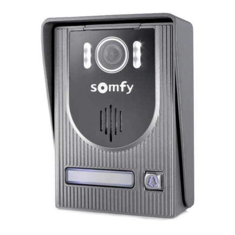
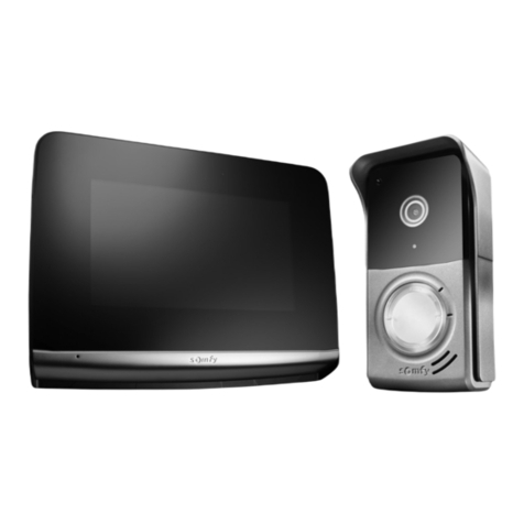
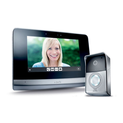
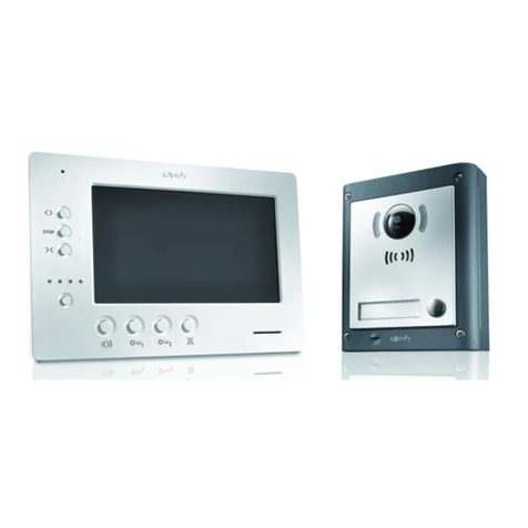
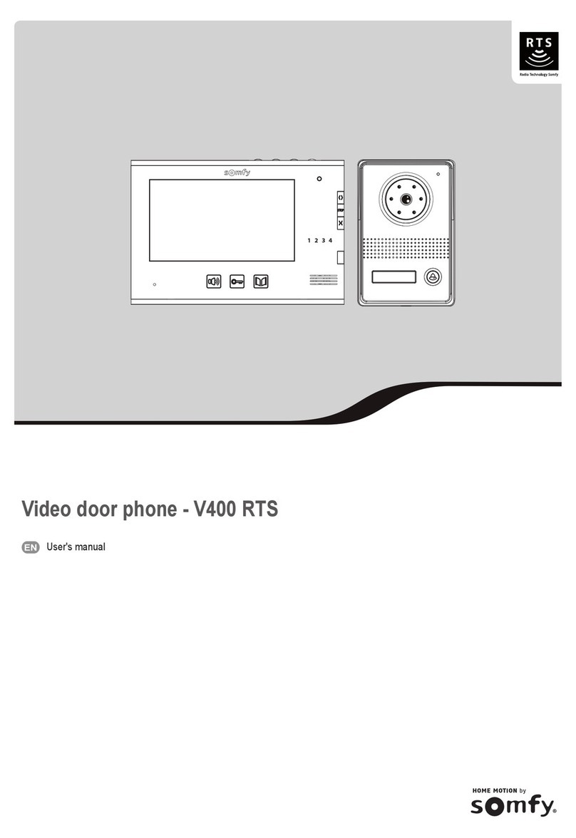
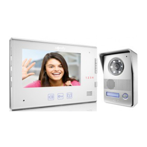
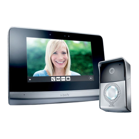
SOMFY HOME MOTION V600 RTS User manual

Video door phone - V600 RTS
EN
Installation instructions
1 2 3 4

1Copyright © 2013 Somfy SAS. All rights reserved.
Video door phone - V600 RTS
EN
CONTENTS
IMPORTANT INFORMATION - SAFETY--------------------------------------------------------------------------------------1
General information 1
General safety advice 1
Conditions for use 2
Recycling 2
PRODUCT DESCRIPTION --------------------------------------------------------------------------------------------------------2
Composition of the kit 2
Product description 3
Dimensions (mm) 4
Standard installation 5
INSTALLING THE MONITOR-----------------------------------------------------------------------------------------------------6
INSTALLING THE DOOR STATION AND ADJUSTING THE CAMERA'S VIEWING ANGLE --------------7
Connecting the door station 8
Fitting the name-tag 8
Switching the installation on 8
SETTING THE FINGERPRINT SCANNER PARAMETERS ------------------------------------------------------------9
Switching to programming mode 9
Possible parameter settings 9
Exiting programming mode 10
VIDEO ENTRY PHONE SETTINGS------------------------------------------------------------------------------------------- 11
Monitor 11
Door station 11
CONTROLLING SOMFY RTS WIRELESS EQUIPMENT ------------------------------------------------------------- 11
Programming the monitor on a Somfy RTS unit 11
STORED FINGERPRINTS MEMORY ----------------------------------------------------------------------------------------16
TECHNICAL DATA ----------------------------------------------------------------------------------------------------------------- 16
IMPORTANT INFORMATION - SAFETY
General information
Read this installation guide and the safety instructions carefully before installing this Somfy product. All the instructions given must be followed
closely and this guide must be stored in a safe place throughout the service life of your product.
Before installation, check that this Somfy product is compatible with the associated equipment and accessories.
This guide describes the installation and use of this product.
Any installation or use outside the sphere of application specied by Somfy is forbidden. This invalidates the warranty and discharges Somfy of
all liability, as does any failure to comply with the instructions given herein.
Somfy cannot be held responsible for any changes in standards which come into effect after the publication of this guide.
Somfy hereby declares that this product conforms to the essential requirements and other relevant provisions of Directive 1999/5/CE. A
Declaration of Conformity is available at www.somfy.com/ce (7" video doorphone).
Images are not contractually binding.
General safety advice
Do not let children play with the control point.
Never immerse the control point in liquid.
This product is not designed to be used by persons (including children) whose physical, sensory or mental capacity is impaired, or persons with
little experience or knowledge, unless they are under supervision or have received instructions on using this product by a person responsible
for their safety.

Copyright © 2013 Somfy SAS. All rights reserved. 2
Video door phone - V600 RTS
EN
Conditions for use
The radio range is limited by the radio appliance control standards.
The radio range is heavily dependent on the environment in which it is used: interference may be caused by having large-scale electrical
equipment near the installation and by the type of material used in the walls and partitions.
The use of a radio appliances (e.g. a set of Hi-Fi radio headphones) operating on the same radio frequency might be detrimental to the product’s
performance.
The recording of digital ngerprints belonging to employees or people working your home is not authorised.
The purpose of this video entry phone camera is to identify a visitor; under no circumstances should it be used to monitor the street or a public
space.
This video entry phone must be used in compliance with the data processing and civil liberties law.
Any use of this product which is not strictly personal is subject to statutory obligations, in particular law no.78-17 of 6 January 1978, according
to which the purchaser is responsible for requesting information from the CNIL, and is required to obtain the administrative permits beforehand.
The purchaser may incur civil and criminal liability in the event of misuse of the device by compromising the right to privacy or the image of a
third-party. Under no circumstances may Somfy be held liable for any use of the video entry phone which contravenes the legal and regulatory
provisions in force.
Recycling
Do not dispose of this product or its at battery with the household waste. Please take them to a collection point or an approved centre
to ensure they are recycled correctly..
123
456
789
*0#
PRODUCT DESCRIPTION
Composition of the kit
No. Description Quantity
1Indoor monitor 1
2Monitor mounting bracket 1
3Power plugs (monitor and door station) 2
4Door station 1
5Rain shield 1
6Biometric reading remote control 1
7Screws + plugs for mounting the monitor and door station 6 + 6
8Torx key 1
x6 x6
x1
x
6
x
6
x
1
3
x 2
6
7
8
1
2
4
5

3Copyright © 2013 Somfy SAS. All rights reserved.
Video door phone - V600 RTS
EN
Product description
The video entry phone comprises an indoor monitor and a door station equipped with a ngerprint scanner. The indoor monitor is connected to the
door station using 2 wires. The door station can then be connected to a gate motorisation or to an electric door-opener/lock, 12 V AC or DC - 800A
max. This allows the indoor monitor to be used to control a small or large gate. The ngerprint scanner can control both a large or small gate.
The indoor monitor is also tted with an RTS (Radio Technology Somfy) radio transmitter. This wireless control is used to operate a garage door,
lighting, roller shutters or even a Somfy gate.
►Monitor
1 2 3 4
P1
M -
M+
M -
M+
P2 DC
+
-
19
20 21
1
15
14
16 17 18
2 3 4
8
9
7
6
5
10
11
12
13
No. Designation Description
1Screen Used to view the visitor.
Wired
controls
2Microphone activation button Activates the microphone on the monitor to speak to a visitor.
Enables the monitor bell to be selected.
3Electric door-opener/lock button Controls the electric door-opener/lock.
4Gate button Controls the motorised gate.
Wireless
controls
5Open/On button Control for opening the gate, roller shutter or garage door or for switching lighting
on.
6STOP Button Stops the movement of the gate, roller shutter or garage door.
7Closed/Off button Control for closing the gate, roller shutter, garage door or for switching lighting off.
8Channel selection button Enables the radio channel controlling a product or a group of products to be
selected: garage door, roller shutter, lighting, gate or product associated with the 5th
channel (see page 11 for more information on the channels).
9Channel indicator lights Each indicator light represents one channel.
10 Photo button Enables a photo to be taken.
11 Read button Used to switch to individual or multiple photo read mode.
12 Navigation button Enables the previous photo to be viewed.
13 Navigation button Enables the next photo to be viewed.
14 Microphone activation indicator
light
This informs the user that the microphone on the monitor is on to enable
communication with the visitor.
15 Bell volume dial This is used to adjust the volume of the monitor bell.
16 Screen colours dial This is used to adjust the screen colours on the monitor.
17 Screen brightness dial This is used to adjust the screen brightness on the monitor.
18 Speaker volume dial This is used to adjust the volume of the speaker on the monitor.
19 PROG button This is used to program the monitor to wirelessly control RTS (Radio Technology
Somfy) equipment.
20 Battery housing Housing for CR2430-type battery (battery included) on the radio transmitter.
21 Terminal block This is used to connect the monitor to the door station and the power supply.

Copyright © 2013 Somfy SAS. All rights reserved. 4
Video door phone - V600 RTS
EN
1 2 3 4
No. Designation Description
1Rain shield Protects the camera from the rain.
2Camera Films the visitor and send the image to the monitor.
3Led lighting Provides enhanced night vision.
4Speaker This enables the visitor to hear the person indoors.
5Infrared cell Place the adjustment remote control opposite this cell during the ngerprint scanner
adjustment steps.
6Fingerprint scanner Enables the visitor, whose digital ngerprint is already stored, to control opening of the
gate or to control the electric door-opener/lock.
7Backlit name-tag label Indicates your name on a label.
8Backlit call button Visitors can use this button to ring the bell on the monitor. The camera and the monitor
screen are switched on.
9Microphone This enables the visitor to speak to the person indoors.
10 Terminal block Used to connect the monitor station to a gate motorisation or an electric door-opener/lock.
11 Speaker volume adjustment button This is used to adjust the volume of the door station speaker.
►Door station
1
10
11
2
3
8
9
7
6
5
4
Dimensions (mm)
(thickness with
rain shield)
(thickness with
metal bracket)
225 130 80
150
260
29

5Copyright © 2013 Somfy SAS. All rights reserved.
Video door phone - V600 RTS
EN
230V
Sealed unit*
Standard installation
1 2 3 4
1 2 3 4
2 x 0.75 mm² min.
* Optional
2-wire
2 x 0.75 mm² min.
Distance between the door
station and the monitor
Cable to be used
Less than 70 m 2-wire 0.5 mm² min.
Between 70 and 100 mm 2-wire 0.75 mm² min.
Note: We recommend that, if possible, the video entry phone cables should not be routed through the same sheath as the electric cables.
The cables are not supplied.
►Door station power plug
The door station power plug can be installed either inside the house or outside, next to the door station.
* You can add a second monitor (ref. 1841206) to your installation -
max. distance between 2 monitors = 30 m
Important: The maximum distance between the monitor and the door station is 100 m.
1 2 3 4
→Inside the house
Feed 2 additional wires between the door station position and the inside of the house.
→Outside, next to the door station
Feed the power plug wires into a duct or electric tube and
install the plug in a sealed unit*.
2-wire
Distance between the door station
and its power plug
Cable to be used
Less than 70 m 2-wire 0.5 mm² min.
Between 70 and 100 mm 2-wire 0.75 mm² min.
* Not supplied

Copyright © 2013 Somfy SAS. All rights reserved. 6
Video door phone - V600 RTS
EN
INSTALLING THE MONITOR
[1]. Fix the monitor mounting plate to the wall.
Important: Ensure the direction of tting is correct by positioning the arrow upwards ("UP" facing upwards) as indicated on the illustration.
[2]. Remove the DC connector from the rear of the monitor and connect the cable from the power plug to this connector: black wire with white
lines on the left (+) and black wire on the right (-).
[3]. Connect the power plug connector to the DC input at the rear of the monitor in the direction indicated in the illustration (screws to the right);
the direction in which the wires are connected to the power plug is important.
Important: It is essential to use the power plug provided to supply the monitor.
Prepare the monitor for connection to the door station by connecting a 2-wire cable to connector P1 at the rear of the monitor.
If you wish to install a second monitor, prepare the connection for this monitor by connecting 2 wires to the P2 connector at the rear of the
monitor, then refer to the guide for the second monitor for additional information on its wiring.
[4]. Clip the monitor onto its mounting bracket by rst positioning the top of the monitor on the station, then the bottom.
Note: Position the power plug wires between the mounting bracket and the monitor.
Power plug wires
1
2
4
+-
P1
M -
M+
M -
M+
P2 DC
+
-
P1
M -
M+
M -
M+
P2 DC
+
-
Monitor
To the door station
To a second monitor
(optional)
3

7Copyright © 2013 Somfy SAS. All rights reserved.
Video door phone - V600 RTS
EN
Avoid installing the camera facing a light source, images of visitors may be impaired.
We recommend that silicon sealant is applied between the rain shield and the wall/pillar (but not below the rain shield) and that the door station
is tted at a height of approximately 1.60 m.
INSTALLING THE DOOR STATION AND ADJUSTING THE CAMERA'S VIEWING
ANGLE
[1]. Feed all the cables (monitor, gate and electric door-opener/lock) into the rain shield.
[2]. Fix the rain shield to the wall/pillar.
[3]. Connect: - the monitor cable to terminals M+ and M- of the door station:
M+ of the monitor to M+ of the door station
M- of the monitor to M- of the door station
- the motorisation cable to the dry contact output (COM and NO) of the door station
- the electric door-opener/lock cable to terminals + and - of the door station.
- the power plug to the + and - terminals of the door station: black wire with white lines to + and all black wire to -.
Note: To feed the cables into the terminals, use a screwdriver to press on the square with the notch, feed the wires in, then release.
[4]. The ngerprint scanner enables a visitor to control the gate and electric door-opener/lock connected to the door station.
With the dipswitch S1 at the rear of the door station, select the automatic control system to be controlled by the ngerprint scanner:
S1 = OFF: the gate is controlled
S1 = ON: the electric door-opener/lock is controlled
Note: The door station must be switched off in order to change the position of S1.
[5]. If you wish to change the camera's viewing angle, unscrew the screw at the rear of the door station slightly, move the camera to the desired
position, then retighten the screw while holding it in the chosen position.
[6]. Install the door station in the rain shield.
[7]. Screw the door station to the rain shield using the torx key.
12
3 6
7
Gate motorisation
cable
Monitor
cable
Power
supply cable
Electric door-
opener/lock cable
S1
OFF
ON
OFF:
ON:
5
4

Copyright © 2013 Somfy SAS. All rights reserved. 8
Video door phone - V600 RTS
EN
800 mA max
*
►To a door-opener/electric lock
Connect the door station output on the door station to the door-opener/lock in accordance with the diagram below.
Note: To connect the door station to another brand of gate motorisation, please refer to the installation guide for that motorisation.
* not provided
Connecting the door station
►To a gate motorisation
Note: When the motorisation is solar-powered, the wired controls are deactivated. In this case, you must use the monitor's wireless control to
control your gate motorisation (see page 11).
Connect the door station dry contact output (COM and NO) to the dry contact input for the motorisation electronics.
Fitting the name-tag
[1]. Press and push on the left-hand side of tag.
[2]. Use a screwdriver to lift and remove the name-tag label protector.
[3]. Write your name on the white label using a permanent marker, then replace the label and its protector in their housing.
Switching the installation on
Once installation is complete, reconnect the gate motorisation to the power supply.
Then connect the monitor and door station power plugs to the electric sockets.
Important: The monitor power plug must be installed close to the monitor and must be easily accessible.
The door station power plug can be installed inside the house or outside in a sealed unit (see page 5).
Your name

9Copyright © 2013 Somfy SAS. All rights reserved.
Video door phone - V600 RTS
EN
SETTING THE FINGERPRINT SCANNER PARAMETERS
Important: To set the parameters for the door station ngerprint scanner, place the adjustment remote control supplied with the video entry
system opposite the door station infrared cell (no. 5, page 4).
*3
+
+x x x xx x x x
x x x
vert
#
3 sec
Code administrateur
=
1 2 3 4
→Changing the administrator code
[1]. Switch to programming mode.
[2]. Press *(star) then 3 on the adjustment remote control.
The indicator light above the scanner ashes yellow.
[3]. Enter your new 4-gure code.
[4]. Enter your new 4-gure code again
The door station emits a beep to conrm. The administrator code has
been changed.
→Forgotten administrator code
[1]. Turn off the door station power supply, then switch the power on again.
[2]. Within 5 seconds of switching the power supply back on, press # on the
adjustment remote control for 3 seconds.
The door station emits a beep to conrm. The default administrator code
of 1234 is restored.
► Storing a ngerprint
Every stored ngerprint is identied by a number which you have allocated
it. Fingerprints can be numbered from 000 to 899.
[1]. Switch to programming mode.
[2]. Enter a 3-gure ngerprint identication number on the adjustment
remote control (for example, 001).
- If the indicator light above the scanner turns green, this ngerprinting
number is available. Carry out step [3].
- If the indicator light above the scanner turns red, this ngerprint
number is already in use. Enter another ngerprint number.
[3]. Ask the person whose ngerprint you wish to store to place their nger
on the ngerprint scanner.
Important: Do not slide your nger over the ngerprint scanner. You just
need to place it on the scanner.
- The door station emits 2 short beeps and then a long one. The
ngerprint is stored.
- If the door station emits one beep, then 3 beeps, the ngerprint has
not been correctly scanned. Place your nger back on the scanner
again to store its print.
- If the door station emits one beep, then 4 beeps, the ngerprint is
already stored.
new
administrator
code
administrator
code
new
administrator
code
administrator
code
administrator code
ngerprint no.
green
+x x x xx x x x
yellow
yellowred
Switching to programming mode
When the indicator light above the scanner lights up red, enter the
administration code twice (default 1234) on the adjustment remote
control.
The indicator turns yellow.
Possible parameter settings
►Administrator code
The administrator code allows entry to the ngerprint scanner's adjustment mode. The default administrator code is 1234.
Copyright © 2013 Somfy SAS. All rights reserved. 10
Video door phone - V600 RTS
EN
► Clearing one or all of the stored ngerprints
→Clearing a ngerprint
[1]. Switch to programming mode.
[2]. Enter the 3-gure ngerprint identication number that you wish to clear
into the adjustment remote control.
[3]. Press *(star) twice.
The indicator above the scanner turns green. The ngerprint is cleared.
x x x
vert
*
+*
+
ngerprint no.
#
→Clearing all the ngerprints
[1]. Switch to programming mode.
[2]. Press *(star) then 8 on the adjustment remote control.
The indicator light above the scanner ashes yellow.
[3]. Press 8 on the adjustment remote control twice.
The door station emits a long beep to conrm. All the ngerprints are
cleared.
*
8
+
8
8+
*5
+
x
x+
*
8
+
9
9+
yellow
yellow
yellow
yellow red
green
security
level
security
level
►Adjusting the security level
This parameter allows recognition sensitivity to be set for the digital
ngerprints.
The security level can be set from 1 (minimum security level) to 5 (maximum
security level).
We advise you to keep the factory security level settings (set at 3).
Note: To adjust the security level, the administrator code must not be the
default administrator code (1234).
[1]. Switch to programming mode.
[2]. Press *(star) then 5 on the adjustment remote control.
The indicator light above the scanner ashes yellow.
[3]. Enter the gure corresponding to the desired security level twice on the
adjustment remote control.
The door station emits a beep to conrm. The security level is set.
- The door station emits three beeps. The security level has not be altered.
Go back to step [2].
►Restoring the factory settings
[1]. Switch to programming mode.
[2]. Press *(star) then 8 on the adjustment remote control.
The indicator light above the scanner ashes yellow.
[3]. Press 9 on the adjustment remote control twice.
The door station emits a long beep to conrm. The factory settings are
restored:
- all the ngerprints are cleared,
- the default administrator code (1234) is restored.
Exiting programming mode
To exit programming mode, press # on the adjustment remote control.
The indicator turns red.
Note: Programming mode is exited automatically after 30 seconds of
inactivity.

11 Copyright © 2013 Somfy SAS. All rights reserved.
Video door phone - V600 RTS
EN
VIDEO ENTRY PHONE SETTINGS
Bell volume dial This is used to adjust the volume of the monitor bell.
Screen colours dial This is used to adjust the screen colours on the monitor.
Screen brightness dial This is used to adjust the screen brightness on the monitor.
Speaker volume dial This is used to adjust the volume of the monitor.
Monitor
Door station
►Adjusting the speaker volume
To adjust the door station speaker volume, use a screwdriver to turn the
button on the back of the door station:
• clockwise to increase the volume,
• anti-clockwise to reduce the volume.
►Changing the monitor bell
There is a choice of two bells for the monitor.
To change the monitor bell, press and hold down the microphone activation button for approximately 7 seconds. The new monitor bell
sounds twice.
To change the bell again, carry out the above operation again.
Button to
adjust the
speaker
volume
CONTROLLING SOMFY RTS WIRELESS EQUIPMENT
Programming the monitor on a Somfy RTS unit
The monitor is equipped with a Somfy Radio Technology (RTS) transmitter. It is only compatible with devices equipped with Somfy Radio
Technology (RTS).
It is used to control the following Somfy equipment, individually or simultaneously:
Canal 1 :
Canal 2 :
Canal 3 :
Canal 4 :
Canal 5 :
Selecting the chosen channel to wirelessly control a piece of equipment
Press the channel selection button the indicator light for the selected channel will ash.
Press the channel selection button as many times as necessary until the indicator lights show the required channel.
Note: All the indicator lights comes on to indicate the 5th channel.
Important: Check that the equipment to be controlled wirelessly is not too far away from the monitor.
• garage door motorisation,
• lighting receiver,
• roller blind motorisation,
• gate motorisation.
This functionality is possible thanks to a channel system, identied by indicator lights.
Each channel corresponds to an individual remote control and can be used to control one or more
devices. There is no limit to the number of devices that can be controlled by a single channel. The
channel selection button (no. 8, page 3) is used to navigate between channels.
Channel 1:
Channel 2:
Channel 3:
Channel 4:
Channel 5:

Copyright © 2013 Somfy SAS. All rights reserved. 12
Video door phone - V600 RTS
EN
►Programming a Somfy Dexxo RTS garage door motor
Note: The monitor can be disconnected from the power supply to carry out this operation.
[1]. Remove the integrated light cover or the motor head ap.
[2]. Check that the motor is powered on.
[3]. Select the rst channel by pressing the channel selection button on the monitor.
[4]. Press the motor PROG button for 2 seconds (button B on a Dexxo Compact RTS).
The motor's integrated light comes on.
[5]. Briey press the monitor opening button.
The motor's integrated light ashes for 5 seconds.
<0,5s
1 2 3 4
1 2 3 4
2s
+SET
PROG
P0
P1
2s
2s
DEXXO PRO RTS
DEXXO OPTIMO RTS
DEXXO COMPACT RTS
<0,5s
1 2 3 4
1 2 3 4
2s
+SET
PROG
P0
P1
2s
2s
DEXXO PRO RTS
DEXXO OPTIMO RTS
DEXXO COMPACT RTS
3
4 5
Note: To clear the programming on the video entry phone on a Somfy garage door motorisation, repeat all the steps detailed above.

13 Copyright © 2013 Somfy SAS. All rights reserved.
Video door phone - V600 RTS
EN
2 mn
2 s 2 s
5 s
5 s
P1
M - M+
P2 DC
+
-
Caution: The receiver uses a 230V power supply. For your safety, ensure that you do not touch the terminal or the bare wires.
Note: The monitor can be disconnected from the power supply to carry out this operation.
[1]. Open the lighting receiver.
[2]. Check that the receiver is powered on.
[3]. Press the PROG button on the receiver until the indicator light on the receiver comes on. The programming function is activated for 2 minutes.
[4]. Select a free channel by pressing the channel selection button on the monitor.
[5]. Use a ne-tipped object to briey press the PROG button at the back of the monitor (above the battery housing, no. 19, page 3).
The indicator light on the receiver ashes for 5 seconds.
1 2 3 4
4
3
5
Note: To clear the video entry phone programming on a Somfy lighting receiver, repeat all the steps detailed above.
RTS outdoor lighting receiver RTS indoor lighting receiver
►Programming a Somfy RTS lighting receiver

Copyright © 2013 Somfy SAS. All rights reserved. 14
Video door phone - V600 RTS
EN
►Programming a Somfy RTS radio roller shutter motorisation
Note: The monitor can be disconnected from the power supply to carry out this operation.
[1]. Identify the original control of the roller shutter, i.e. the remote control or the control point which only controls this roller shutter.
Note: - If the original control is lost or broken, and it is the only one to control the roller shutter, contact one of our Somfy advisors.
- If another control operates the roller shutter, use that to follow the steps below.
[2]. Partially open the roller shutter using the original control.
[3]. Press the PROG button on the original control until the roller shutter makes an up and down movement (or a series of 3 beeps). The
programming function is activated for 2 minutes.
[4]. Select a free channel by pressing the channel selection button on the monitor.
[5]. Use a ne-tipped object to briey press the PROG button at the back of the monitor (above the battery housing, no. 19, page 3). The roller
shutter will make an up and down movement (or a series of 8 beeps).
Note: To clear the programming on the video entry phone on a Somfy roller shutter motorisation, repeat all the steps detailed above.
Emetteur RTS d'origine
Moniteur
1 2 3 4
P1
M - M+
P2 DC
+
-
Emetteur RTS d'origine
Moniteur
1 2 3 4
P1
M - M+
P2 DC
+
-
Emetteur RTS d'origine
Moniteur
1 2 3 4
P1
M - M+
P2 DC
+
-
4
3
5
Original RTS transmitter
Monitor
Back of control point Back of remote control

15 Copyright © 2013 Somfy SAS. All rights reserved.
Video door phone - V600 RTS
EN
►Programming a Somfy RTS gate motorisation
Note: The monitor can be disconnected from the power supply to carry out this operation.
[1]. Access the motorisation electronics.
[2]. Check that the motor is powered on.
[3]. Remove the monitor from its mounting bracket.
Select a free channel by pressing the channel selection button on the monitor.
[4]. On an Axovia 220B or an Elixo Optimo: place the monitor on the target on the motor electronic unit.
Important: The right-hand section of the monitor must be placed on the electronic unit target so that the monitor can be correctly detected
by the motor electronics.
On an Elixo 800/1300/2000, an Elixo 500 230V RTS, an Elixo 500 3S RTS or a Control Box 3S RTS, press the PROG button for 2 seconds.
[5]. Briey press the monitor opening button.
Note: To program the monitor on a motorisation other than those described above, refer to the guide for this motorisation.
1 2 3 4
1 2 3 4
1 2 3 4
RADIO
RESET
=
=
RADIO
RESET
=
=
< 0,5s
AXOVIA 220B RTS
ELIXO OPTIMO RTS
ELIXO 800/1300/2000 RTS
CONTROL BOX 3S RTS
ELIXO 500 3S RTS
PROG
2s
PROG
PROGPR
OG
PR
OG
< 0,5s
2s
Add
< 0,5s
ELIXO 500 230V RTS
1 2 3 4
1 2 3 4
1 2 3 4
RADIO
RESET
=
=
RADIO
RESET
=
=
< 0,5s
AXOVIA 220B RTS
ELIXO OPTIMO RTS
ELIXO 800/1300/2000 RTS
CONTROL BOX 3S RTS
ELIXO 500 3S RTS
PROG
2s
PROG
PROGPR
OG
PR
OG
< 0,5s
2s
Add
< 0,5s
ELIXO 500 230V RTS
4
5
6
Note: To clear the video entry phone programming on a Somfy gate motorisation, see the motorisation guide.

Copyright © 2013 Somfy SAS. All rights reserved. 16
Video door phone - V600 RTS
EN
Monitor
Power supply 100-240 VAC/ 50-60 Hz; 17 VDC
Screen Colour - TFT 7" - resolution: 480 x 234 pixels
Max. communication time 2 minutes
Operating temperature -10°C to +55°C
Radio transmitter Frequency 433.42 MHz
Power supply 3 V type CR2430
Range 200 m (in open space)
Door station
Power supply 14.5 V DC
Camera 1/3 CCD 72°
Night vision 0.05 LUX visible LEDs
Operating temperature -20°C to +55°C
TECHNICAL DATA
STORED FINGERPRINTS MEMORY
Fingerprint no. Name

Somfy SAS, capital 20.000.000 Euros, RCS Annecy 303.970.230 - Copyright © Somfy SAS. All rights reserved - 09/2013
Argentina : Somfy Argentina
+55 11 (0) 4737-37000
Australia : Somfy PTY LTD
+61 (0) 2 9638 0744
Austria : Somfy GesmbH
+43(0) 662 / 62 53 08 - 0
Belgium : Somfy Belux
+32 (0)2 712 07 70
Brasil : Somfy Brasil STDA
+55 11 (0) 6161 6613
Canada : Somfy ULC
+1 (0) 905 564 6446
China : Somfy China Co. Ltd
+8621 (0) 6280 9660
Cyprus : Somfy Middle East
+357 (0) 25 34 55 40
Czech Republic : Somfy Spol s.r.o.
(+420) 296 372 486-7
Denmark : Somfy Nordic AB Denmark
+45 65 32 57 93
Finland : Somfy Nordic AB Finland
+358 (0) 957 13 02 30
France : Somfy France
+33 (0) 820 374 374
Germany : Somfy GmbH
+49 (0) 7472 9300
Greece : Somfy Hellas
+30 210 614 67 68
Hong Kong : Somfy Co. Ltd
+852 (0) 2523 6339
Hungary : Somfy Kft
+36 1814 5120
India : Somfy India PVT Ltd
+91 (0) 11 51 65 91 76
Indonesia : Somfy IndonesiaEra
+62 (0) 21 719 3620
Iran : Somfy Iran
+98 21 88 63 52 43
Israel : Sisa Home Automation Ltd
+972 (0) 3 952 55 54
Italy : Somfy Italia s.r.l
+39-024 84 71 84
Japan : Somfy KK
+81 (0)45-475-0732
+81 (0)45-475-0922
Jordan : Somfy Jordan
+962-6-5821615
Kingdom of Saudi Arabia :
Somfy Saoudi
Riyadh : +966 1 47 23 203
Jeddah : +966 2 69 83 353
Kuwait : Somfy Kuwait
00965 4348906
Lebanon : Somfy Middle East
+961(0) 1 391 224
Malaisia : Somfy Malaisia
+60 (0) 3 228 74743
Mexico : Somfy Mexico SA de CV
+52(0) 55 5576 3421
Morocco : Somfy Maroc
+212-22951153
Netherlands : Somfy BV
+31 (0) 23 55 44 900
Norway : Somfy Norway
+47 67 97 85 05
Poland : Somfy SP Z.O.O
+48 (0) 22 509 53 00
Portugal : Somfy Portugal
+351 229 396 840
Romania : Somfy SRL
+40 - (0)368 - 444 081
Russia : Somfy LLC
+7 095 781 47 72
Singapore : Somfy PTE LTD
+65 (0) 638 33 855
Slovak Republic : Somfy Spol s.r.o.
(+421) 33 77 18 638
South Korea : Somfy JOO
+82 (0) 2 594 4333
Spain : Somfy Espana SA
+34 (0) 934 800 900
Sweden : Somfy Nordic AB
+46 (0) 40 165900
Switzerland : Somfy A.G.
+41 (0) 44 838 40 30
Syria : Somfy Syria
+963-9-55580700
Taïwan : Somfy Taïwan
+886 (0) 2 8509 8934
Thailand : Somfy Thailand
+66 (0) 2714 3170
Turkey : Somfy Turkey
+90 (0) 216 651 30 15
United Arab Emirates : Somfy Gulf
+971 (0) 4 88 32 808
United Kingdom : Somfy LTD
+44 (0) 113 391 3030
United States : Somfy Systems Inc
+1 (0) 609 395 1300
Somfy
50 avenue du Nouveau Monde
BP 152 - 74307 Cluses Cedex
France
www.somfy.com
Somfy Worldwide
Table of contents
Other SOMFY Intercom System manuals

SOMFY
SOMFY V SYSTEM PRO User manual

SOMFY
SOMFY VSYSTEMPRO User manual

SOMFY
SOMFY V500 PRO io User manual

SOMFY
SOMFY One Plus User manual

SOMFY
SOMFY V100 User manual

SOMFY
SOMFY V400 RTS User manual

SOMFY
SOMFY V500 User manual

SOMFY
SOMFY V100 Plus User manual

SOMFY
SOMFY V300 User manual

SOMFY
SOMFY V500 User manual

SOMFY
SOMFY V500 PRO io User manual

SOMFY
SOMFY V350 User manual

SOMFY
SOMFY VSYSTEMPRO User manual

SOMFY
SOMFY V100+ User manual

SOMFY
SOMFY VSYSTEMPRO Origin RTS User manual

SOMFY
SOMFY V100 User manual

SOMFY
SOMFY V300 User manual

SOMFY
SOMFY VSYSTEMPRO User manual

SOMFY
SOMFY V200 RTS User manual

SOMFY
SOMFY HOME DPV 25B User manual