3 (E)
BKMA-506
Manual Structure
Purpose of this manual
This manual is the installation manual of the BKMA-506 DDR Control Panel Case
Kit.
This manual is intended for use by trained system and service engineers, and
describes the information regarding installation.
Related manuals
Besides this Installation Manual, the following manuals are available for the
BKMA-506.
..
..
.MAV-555 Series
Maintenance Manual Volume 1 (available on request)
This manual describes the information that premises the service based on parts
replacement (diagnostics, parts replacement, electrical alignment, and circuit
descriptions, etc.).
If this manual is required, please contact your local Sony Sales Office/Service
Center.
..
..
.MAV-555 Series
Maintenance Manual Volume 2 (available on request)
This manual describes the information that premise the service based on parts
replacement (parts list, block diagrams, schematic diagrams, board layouts, etc.).
If this manual is required, please contact your local Sony Sales Office/Service
Center.
Contents
The following is a summary of all the section for understanding the contents of this
manual.
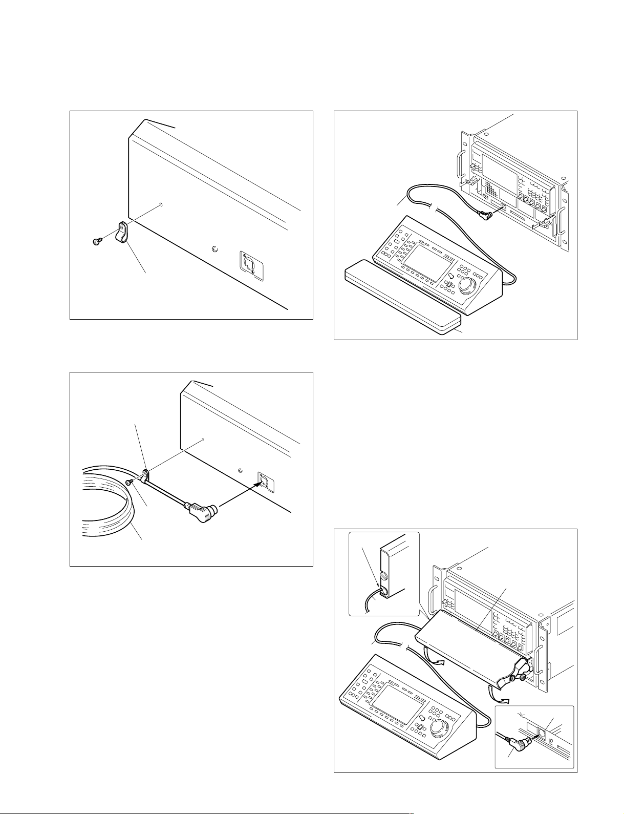
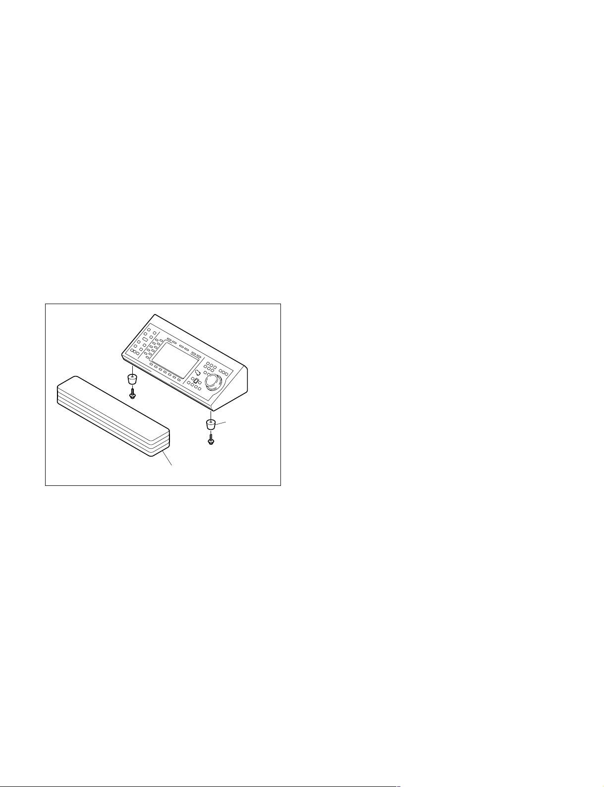
Section 1 Installation
Explains the overview of the BKMA-506, how to install the BKMA-506 to the
MAV-555.
Section 2 Service Overview
Explains the specifications and the list of periodic replacement parts of the BKMA-
506.