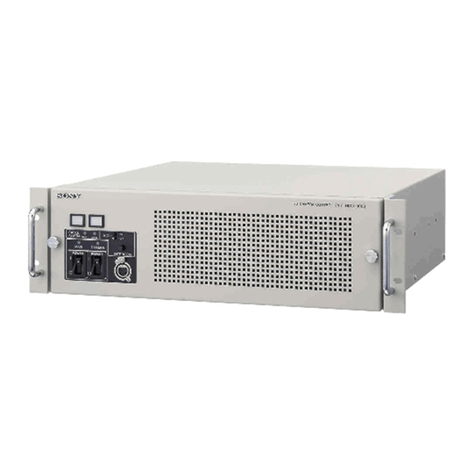
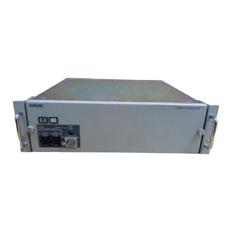
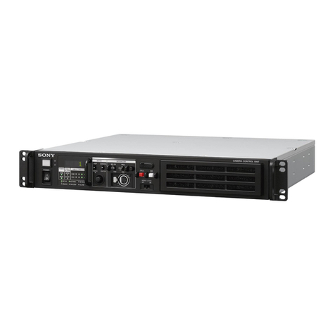
Sony BVE-700A User manual

EDITING CONTROL UNIT
BVE-700A
SWITCHER BOARD
BKE-701A
MAINTENANCE MANUAL
1st Edition
Serial No. 10001 and Higher: BVE-700A
Serial No. 10001 and Higher: BKE-701A

BVE-700A
!WARNING
This manual is intended for qualified service personnel only.
To reduce the risk of electric shock, fire or injury, do not perform any servicing other than that
contained in the operating instructions unless you are qualified to do so. Refer all servicing to
qualified service personnel.
!WARNUNG
Die Anleitung ist nur für qualifiziertes Fachpersonal bestimmt.
Alle Wartungsarbeiten dürfen nur von qualifiziertem Fachpersonal ausgeführt werden. Um die
Gefahr eines elektrischen Schlages, Feuergefahr und Verletzungen zu vermeiden, sind bei
Wartungsarbeiten strikt die Angaben in der Anleitung zu befolgen. Andere als die angegeben
Wartungsarbeiten dürfen nur von Personen ausgeführt werden, die eine spezielle Befähigung
dazu besitzen.
!AVERTISSEMENT
Ce manual est destiné uniquement aux personnes compétentes en charge de l’entretien. Afin
de réduire les risques de décharge électrique, d’incendie ou de blessure n’effectuer que les
réparations indiquées dans le mode d’emploi à moins d’être qualifié pour en effectuer d’autres.
Pour toute réparation faire appel à une personne compétente uniquement.
For the customers in the Netherlands
Voor de klanten in Nederland
Hoe u de batterijen moet verwijderen, leest u in de tekst
van deze handleiding.
Gooi de batterij niet weg maar lever deze in als klein
chemisch afval (KCA).
Für Kunden in Deutschland
Entsorgungshinweis: Bitte werfen Sie nur entladene
Batterien in die Sammelboxen beim Handel oder den
Kommunen. Entladen sind Batterien in der Regel dann,
wenn das Gerät abschaltet und signalisiert “Batterie
leer” oder nach längerer Gebrauchsdauer der Batterien
“nicht mehr einwandfrei funktioniert”. Um
sicherzugehen, kleben Sie die Batteriepole z.B. mit
einem Klebestreifen ab oder geben Sie die Batterien
einzeln in einen Plastikbeutel.
For safety, do not connect the connector for peripheral
device wiring that might have excessive voltage to the
following port(s).
BVE-700A
: NETWORK connector
Follow the instructions for the above port(s).

BVE-700A
Vorsicht!
Explosionsgefahr bei unsachgemäßem Austausch
der Batterie.
Ersatz nur durch denselben oder einen vom
Hersteller empfohlenen ähnlichen Typ. Entsorgung
gebrauchter Batterien nach Angaben des
Herstellers.
ATTENTION
Il y a danger d’explosion s’il y a remplacement
incorrect de la batterie.
Remplacer uniquement avec une batterie du même
type ou d’un type équivalent recommandépar le
constructeur.
Mettre au rebut les batteries usagées conformément
aux instructions du fabricant.
ADVARSEL!
Lithiumbatteri-Eksplosionsfare ved fejlagtig
håndtering.
Udskiftning måkun ske med batteri
af samme fabrikat og type.
Levér det brugte batteri tilbage til leverandøren.
ADVARSEL
Lithiumbatteri - Eksplosjonsfare.
Ved utskifting benyttes kun batteri som
anbefalt av apparatfabrikanten.
Brukt batteri returneres
apparatleverandøren.
VARNING
Explosionsfara vid felaktigt batteribyte.
Använd samma batterityp eller en likvärdig typ
som rekommenderas av apparattillverkaren.
Kassera använt batteri enligt gällande
föreskrifter.
VAROITUS
Paristo voi räjähtää jos se on virheellisesti
asennettu.
Vaihda paristo ainoastaan laitevalmistajan
suosittelemaan tyyppiin.
Hävitäkäytetty paristo valmistajan ohjeiden
mukaisesti.
CAUTION
Danger of explosion if battery is incorrectly replaced.
Replace only with the same or equivalent type
recommended by the manufacturer.
Dispose of used batteries according to the
manufacturer’s instructions.
1 (P)


1 (E)
BVE-700A
Table of Contents
Manual Structure
Purpose of this manual ........................................................... 3 (E)
Related manuals ..................................................................... 3 (E)
Contents .................................................................................. 4 (E)
Trademarks ............................................................................. 4 (E)
1. Service Overview
1-1. Locations of Main Parts ........................................... 1-1 (E)
1-2. Removing the Cabinets ............................................ 1-3 (E)
1-2-1. Removing Cabinets of Processor Unit ........... 1-3 (E)
1-2-2. Removing the Cabinets of
Control Panel Unit .......................................... 1-4 (E)
1-3. Replacing the Main Parts ......................................... 1-4 (E)
1-3-1. Replacing the Switching Regulator ................ 1-4 (E)
1-3-2. Replacing the DC Fan .................................... 1-6 (E)
1-3-3. Replacing the CPU-DT Module ..................... 1-7 (E)
1-3-4. Precautions when Replacing Memory or
Writing Device on CA-67 Board ................... 1-8 (E)
1-3-5. Writing the PLD Data .................................... 1-9 (E)
1-3-6. Writing the Flash Memory ............................. 1-9 (E)
1-3-7. Replacing the Fuse and IC Link ................... 1-12 (E)
1-3-8. Replacing the Backup Battery ...................... 1-12 (E)
1-4. Fixtures .................................................................. 1-13 (E)
1-5. Unleaded Solder ..................................................... 1-13 (E)
1-6. Periodic Inspection ................................................ 1-14 (E)
1-6-1. Periodic Replacement Parts .......................... 1-14 (E)
1-6-2. Cleaning ....................................................... 1-14 (E)
1-7. Using the Extension Board .................................... 1-15 (E)
1-8. Troubleshooting ..................................................... 1-16 (E)
1-8-1. Processor Unit Hardware Test ...................... 1-16 (E)
1-8-2. Control Panel Unit ........................................ 1-32 (E)
1-9. Circuit Description ................................................. 1-37 (E)
2. Spare Parts
2-1. Notes on Repair Parts ..................................................... 2-1
2-2. Exploded Views .............................................................. 2-2
2-3. Electrical Parts List ....................................................... 2-10
2-3-1. BVE-700A ........................................................... 2-10
2-3-2. BKE-701A ........................................................... 2-31
2-3-3. Supplied Accessories ........................................... 2-41
3. Semiconductor Pin Assignments
4. Block Diagrams
4-1. BVE-700A ...................................................................... 4-1
Overall ............................................................................ 4-1
CA-67 ............................................................................. 4-4
CN-2836 ......................................................................... 4-5
SG-272 ............................................................................ 4-5
SIO-26 ............................................................................. 4-5
4-2. BKE-701A ...................................................................... 4-6
OUT-28B ........................................................................ 4-6
CN-2843 ......................................................................... 4-7
5. Board Layouts
5-1. BVE-700A ...................................................................... 5-2
CA-67 ............................................................................. 5-2
HN-314 ........................................................................... 5-4
CN-2835 ......................................................................... 5-5
CN-2836 ......................................................................... 5-6
MB-1092 ......................................................................... 5-7
SG-272 ............................................................................ 5-8
SIO-26 ............................................................................. 5-8
DP-425 ............................................................................ 5-9
DP-426 .......................................................................... 5-10
PTC-106 ........................................................................ 5-10
IF-23 ............................................................................. 5-11
5-2. BKE-701A .................................................................... 5-12
OUT-28 ......................................................................... 5-12
CN-2843 ....................................................................... 5-16

2 (E) BVE-700A
6. Schematic Diagrams
6-1. BVE-700A ...................................................................... 6-3
CA-67 .............................................................................6-3
CN-2835 ....................................................................... 6-22
CN-2836 ....................................................................... 6-23
MB-1092 ....................................................................... 6-24
HN-314 ......................................................................... 6-27
SG-272 .......................................................................... 6-28
SIO-26 ........................................................................... 6-31
DP-425 .......................................................................... 6-36
DP-426 .......................................................................... 6-40
IF-23 ............................................................................. 6-41
KY-613 ......................................................................... 6-44
PTC-106 ........................................................................ 6-50
Frame Wiring ................................................................ 6-51
6-2. BKE-701A .................................................................... 6-53
CN-2843 ....................................................................... 6-53
OUT-28B ...................................................................... 6-55

3 (E)
BVE-700A
Purpose of this manual
This manual is the maintenance manual of Editing Control Unit BVE-700A and
Switcher Board BKE-701A.
This manual is intended for use by trained system and service engineers, and
describes the information that premise the service based on components replace-
ment.
Related manuals
Beside this Maintenance Manual, the following manuals are available for the unit.
..
..
.User’s Guide (Supplied with BVE-700A)
This manual describes the application and operation of the unit.
..
..
.Operation Manual (Supplied with BVE-700A)
This manual describes the overview, system connection examples, and specifica-
tions of the unit.
..
..
.Installation Manual (Supplied with BVE-700A)
This manual describes the information related to the installation of the unit.
..
..
.BKE-701A Installation Manual (Supplied with BKE-701A)
This manual describes the information related to the installation of the unit.
..
..
.BKE-701A Operation and Installation Guide (Supplied with BKE-701A)
This manual describes the notes for installing BKE-701A.
..
..
.“Semiconductor Pin Assignments” CD-ROM (Available on request)
This “Semiconductor Pin Assignments” CD-ROM allows you to search for
semiconductors used in Broadcast and Professional equipment.
The maintenance manual contains a complete list of semiconductors and their ID
Nos., and thus should be used together with the CD-ROM.
Part number: 9-968-546-XX
Manual Structure

4 (E) BVE-700A
Contents
This manual is organized by following sections.
Section 1 Service Overview
Describes fundamental area of the information that is required to service (removal of
cabinet and locations of main part), writing the flash memory and troubleshooting,
etc.
Section 2 Spare Parts
Describes the spare parts list and exploded views.
Section 3 Semiconductor Pin Assignments
Contains information on semiconductors used for the unit.
It includes a complete list of the semiconductors and their ID Nos. for retrieving
information on “Semiconductor Pin Assignments” CD-ROM, which is available
separately.
Please refer to this section together with the “Semiconductor Pin Assignments” CD-
ROM.
Section 4 Block Diagrams
Describes the block diagram.
Section 5 Board Layouts
Describes the board layout for circuit boards.
Section 6 Schematic Diagrams
Describes the schematic diagram for circuit boards and frame wiring.
Trademarks
Trademarks and registered trademarks used in this manual are follows.
.
Windows is a registered trademark of Microsoft Corporation.
.IBM is a registered trademark of International Business Machines Corporation.
.Ethernet is a registered trademark of Xerox Corporation.

1-1 (E)
BVE-700A
1-1. Locations of Main Parts
Processor unit
No. Board Function
1OUT-28B board (BKE-701A) HD Video Switcher
2CA-67 board Main CPU
3CPU-DT Module CPU-DT Module
4SG-272 board Signal Generator
5SIO-26 board Serial Interface
6CN-2487 board Connector
7CN-2843 board (BKE-701A) HD SDI Interface
8CN-2835 board Connector
9CN-2836 board Connector
0HN-314 board Fan Connector
!- MB-1092 board Motherboard
Section 1
Service Overview
DC fan
Switching regulator
1
7CN-2843 board
(BKE-701A) (Option)
2CA-67 board
(Including CPU-DT module, SIO-26 board, and SG-272 board)
5SIO-26 board
6CN-2487 board
0HN-314 board
4SG-272 board
3CPU-DT module
OUT-28B board
(BKE-701A) (Option)
8CN-2835 board
9CN-2836 board
!- MB-1092 board

1-2 (E) BVE-700A
Control panel unit
No. Board Function
1IF-23 board Control Panel CPU
2DP-425 board 7SEG LED
3DP-426 board ASCII Display/LED
4PTC-106 board Dial Pulse Waveform Shaping
3
2
1
PTC-106 board
PTC-106 board
Keyboard unit
DP-425 board
IF-23 board
Electromagnetic clutch assembly
DP-426 board
4
4

1-3 (E)
BVE-700A
1-2. Removing the Cabinets
1-2-1. Removing Cabinets of Processor Unit
1. Turn off the main power, and disconnect the plug from
the outlet.
2. Loosen the four screws (with drop-safe) and remove
the front panel.
3. Loosen the two screws (with drop-safe), press the two
levers in the direction of arrow A, and remove the CN-
2836 board.
4. Loosen the two screws (with drop-safe) and remove
the CN-2835 board.
(If the optional CN-2843 board (BKE-701A) is
attached, remove it in the same manner.)
5. Loosen the two screws (with drop-safe) and remove
the fan assembly from the connector CN3 on the MB-
1092 board.
6. Remove the four screws and remove the two board
lever bases.
7. Remove the eight screws aand pull out the rear
panel slightly in the direction of arrow A.
8. Remove the harness from the connector CN2 on the
MB-1092 board and remove the rear panel.
9. Remove the sixteen screws band remove the top
panel in the direction of arrow B.
B4 x10
(with drop-safe)
B4 x10
(with drop-safe)
B4 x10
(with drop-safe)
Front panel
Screws
(with drop-safe)
Screws
(with drop-safe)
CN-2835 board
CN-2836 board
Optional
CN-2843 board (BKE-701A)
Lever
Lever
AA
MB-1092 board
CN3
Board lever bases
B2 x6
B2 x6
Screws
(with drop-safe)
Fan assembly
Harness
Top panel
Rear panel
PSW3 x8
B4 x6
MB-1092 board
CN2
Washer
B4 x6
B4 x6
B4 x6
PS4 x8
B3 x5
B3 x5
B3 x5
b
b
b
b
b
a
a
a
A
B

1-4 (E) BVE-700A
1-3. Replacing the Main Parts
1-3-1. Replacing the Switching Regulator
Replacement part
Part name : Switching regulator
Part No. : !1-468-480-21
Replacement procedure
1. Turn off the main power, and disconnect the plug from
the outlet.
2. Remove the front panel. (Refer to Section 1-2-1.)
3. Remove the two screws and pull out the power supply
unit in the direction of the arrow while holding the
handle.
n
For the replacement of the power supply unit, please
buy HK-PSU02.
1-2-2. Removing the Cabinets of Control
Panel Unit
1. Remove the connection cable leading to the processor
unit.
2. Remove the eight screws and remove the top panel
assembly.
3. Remove the flat cable from the connector CN201 on
the IF-23 board.
B3 x6
CN201
IF-23 board
B3 x6
B3 x6
B3 x6
Top panel assembly
Connection cable
To the
processor
unit
Flat cable
PSW3 x6
Power supply unit
(HK-PSU02)
Handle

1-5 (E)
BVE-700A
Power supply voltage check after replacement
n
After replacing the power supply unit or the switching
regulator, be sure to check power supply voltage.
Required equipment : Digital voltmeter
Check procedure
1. Remove the front panel and the PWB stopper. (Refer
to Section 1-2-1 and 1-3-3.)
2. Extend the CA-67 board using the extension board
EX-840. (Refer to Section 1-7.)
3. Turn on the power of power supply unit.
4. Connect the digital voltmeter to the +12 V terminal
(TP1800) and GND terminal (E1800) of the CA-67
board.
5. Confirm that the power supply voltage meets the
specifications.
Specifications : +12.0 ±0.6 V
Procedure after check
1. Remove the digital voltmeter.
2. Insert the CA-67 board into the board slot, and then
attach the PWB stopper and front panel.
4. Cut the binding band which has bound the harness.
5. Disconnect the harness from the connector (CN1) on
the CN-2487 board.
6. Disconnect the harness from the connector (CN203)
on the switching regulator.
7. Remove the four screws, and remove the two conduc-
tion plates.
8. Remove the two screws, and remove the switching
regulator.
9. Attach a new switching regulator.
n
Bind the harnesses of CN1 and CN203 as before by a
new binding band respectively.
Harnesses
CN1
CN203
CN4
CN202
CN201
CN3
PSW4 x8
PSW3 x6
PSW4 x8
Switching regulator
Conduction
plates
CN-2487 board
TP1800
E1800
CA-67 Board

1-6 (E) BVE-700A
1-3-2. Replacing the DC Fan
m
.One DC fan have been installed in the BVE-700A.
.It is recommended to replace the DC fan every time the
BVE-700A is used for about three years.
Replacement part
Part name : DC fan
Part No. : 1-698-890-21
Replacement procedure
1. Turn off the main power, and disconnect the plug from
the outlet.
2. After fully loosening the two screws (with drop-safe),
remove the DC fan assembly from the connector
(CN3) on the MB-1092 board in the direction of the
arrow while holding the screws.
3. Remove the two screws, and the fan panel.
4. Remove the two screws, and remove the fan attach-
ment plate (2).
5. Slide the DC fan in the direction of the arrow from the
fan attachment plate (1) and disconnect the harness
from the connector (CN2) on the HN-314 board.
6. Attach a new DC fan in reverse order of steps 2 to 5.
n
Attach the DC fan in the direction shown below.
Screws
(with drop-safe)
Fan assembly
MB-1092 board
CN3
Fan attachment plate (1)
Fan panel
Fan attachment plate (2)
DC fan
HN-314 board
CN2
BVTT3 x5
BVTT3 x5
BVTT3 x5
HN-314 board
CN2
CN1

1-7 (E)
BVE-700A
5. Remove the three screws, and remove the bracket (T).
6. Remove the CPU-DT module from the connector
(CN200) on the CA-67 board.
7. Peel off the ventilation sheet from the removed CPU-
DT module.
n
The ventilation sheet will be reused.
1-3-3. Replacing the CPU-DT Module
n
The CPU-DT module is used in the CA-67 board of the
processor unit.
Replacement part
Part name : CPU-DT module
Part No. : 1-789-288-11
Replacement procedure
1. Turn off the main power, and disconnect the plug from
the outlet.
2. Remove the front panel. (Refer to Section 1-2-1.)
3. Remove the four screws, and remove the PWB
stopper.
4. Open the eject levers in the direction of the arrow A as
shown, and pull the CA-67 board out to remove it.
PWB stopper
Lever
Lever
CA-67 board
B 3 x5
B 3 x5
A
A
B
Bracket (T)
Ventilation sheet
CPU-DT module
B 3 x6
CA-67 board
CN200

1-8 (E) BVE-700A
1-3-4. Precautions when Replacing Memory or Writing Device on CA-67 Board
When replacing the IC part noted below, be sure to perform the following operations.
The board may not operate correctly if the IC part is simply replaced.
Ref. No. Part Number Part Name Remarks
IC803 6-700-757-01 M48T35Y-70MH1F Backup SRAM
IC800,801,802 6-708-352-01 S29JL064H70TFI000 Flash memory
IC1503 6-707-492-01 CAT93C46XI EEPROM for Ethernet address
IC1602 8-759-678-06 CAT24WC02WI-TE13 EEPROM for model data
1. When Replacing IC803 (Backup SRAM)
Set the S901-8 switch on the CA-67 board to CLOSE. Turn the power off and on, and then set S901-
8 to OPEN again. Finally, reset the backup memory SETUP DATA to factory defaults. (For more
details, refer to the User’s Guide.)
2. When Replacing IC800, 801, 802 (Flash Memory)
Perform “1-3-6. Writing the Flash Memory”.
3. When Replacing IC1503 (EEPROM for Ethernet Address)
Use “3. MAC Address” in the Utility menu noted under “1-8-1. Processor Unit Hardware Test” to
write the MAC address. The MAC address is written on the sticker placed near the A-side address 3-
H on the CA-67 board.
4. When Replacing IC1602 (EEPROM for Model Data)
Use “1. I2C EEPROM” in the Utility menu noted under “1-8-1. Processor Unit Hardware Test” to
enter the data.

1-9 (E)
BVE-700A
1-3-5. Writing the PLD Data
This section describes how to upgrade the PLD version of
each board using the PLD download tool.
Equipment required
.A personal computer equipped with the parallel port (For
the target OS, refer to the operation manual supplied
with the PLD Download Tool.)
.PLD Download Tool (J-7120-140-A)
Connection
1. Connect the PLD Download Tool to the parallel port
of the personal computer.
2. Connect the cable (8-pin connector) coming from the
PLD Download Tool to the following connector on the
target board.
Target board Ref. No. Project file No.
CA-67 Board CN400 E-000-002-86-xx
Keyboard Unit CN200 E-000-003-22-xx
n
No setup is required in board.
Downloading
1. Start up the PLD Download Tool Software on the
personal computer.
After reading data for upgrading the PLD version,
write the data and confirm that is correctly written.
n
For details of the operation, refer to the operation
manual of the PLD Download Tool
2. Upon completion of downloading, turn off the main
power of the BVE-700A once.
1-3-6. Writing the Flash Memory
IC800, IC801, and IC802 on the CA-67 board contain a
built-in BVE-700A.
When replacing IC800, IC801, and IC802, the CPU-DT
tool board must be used to download the program and
write it to flash memory.
The CPU-DT tool board uses the following parts.
CPU-DT module (for service)
Part number: 1-789-288-21
Key Program ROM for BVE-700A
Part number: 6-806-423-01
Replace the CPU-DT module on the CA-67 board with the
CPU-DT tool board and download the program. Return the
module and board back to normal after downloading is
complete.
The program can be downloaded from a personal computer
via RS-232C or Ethernet connection.
The following programs and files must be written.
e7a2nd.txt : Boot program
e7aapp.txt : Application program
out28b1.txt : FPGA data
out28b2.txt : FPGA data
Equipment to Use
Personal Computer : IBM-PC compatible with Windows
2000/XP
When using Ethernet : Ethernet (10Base-T/100Base-TX
cross over) connection cable
(commercial product)
When using RS-232C: RS-232C connection cable (com-
mercial product)

1-10 (E) BVE-700A
(5) Return the mode select switch S900-1 on the CA-67
board to OPEN, and turn the power off then on again.
Verify that the BVE-700A starts up correctly.
The display on 7SEG LED (D900 to D915) means the
following.
Display Description
00 Waiting for download
01 Downloading
10 Deleting flash memory
20 Writing flash memory
FF Complete
E0 to EF Error
m
.It normally takes about 10 seconds to download and
write one program or file.
.When rewriting, perform the above procedure from
step 3.
..
..
.Using Internet Explorer to Download
(1) Set the mode select switch S900-1 on the CA-67 board
of BVE-700A to CLOSE (ON) and turn the power on.
(2) Verify that “00”is displayed on 7SEG LED (D900 to
D915) on the CA-67 board, and start up Internet
Explorer.
(3) Enter “ftp://10.10.10.10/”into the Address Bar and
press the Enter key.
At this time, if the dialog message “FTP Folder Error:
Windows cannot access this folder. Make sure you
typed the filename correctly and that you have permis-
sion to access the folder.”appears, click “OK”.
(4) Run Explorer from Program in the Windows Start
menu. Display the folder with the programs and the
files, and use the mouse the drag the programs and the
files into the Internet Explorer window.
(5) Verify that the display on 7SEG LED (D900 to D915)
on the CA-67 board becomes “FF”, indicating that the
downloading and writing to flash memory have
finished.
1. Using Ethernet to Download
There are two methods for downloading with Ethernet:
using Internet Explorer, or using ftp command (included
with Windows 2000/XP).
Ethernet Connection
Using an Ethernet (10Base-T/100Base-TX cross over)
connection cable, connect the NETWORK connector on
the rear panel of BVE-700A to the personal computer for
the download.
Network Settings
Set the IP address and subnet mask for the personal
computer to the following values.
IP address : 10.10.10.1
Subnet mask : 255.0.0.0
n
When using Internet Explorer, change the settings so that a
proxy server is not used.
..
..
.Using ftp Command (included with
Windows2000/XP) to Download
(1) Set the mode select switch S900-1 on the CA-67 board
of BVE-700A to CLOSE (ON) and turn the power on.
(2) Verify that “00”is displayed on 7SEG LED (D900 to
D915) on the CA-67 board.
(3) Run the MS DOS Prompt from Program in the Win-
dows Start menu. Transfer the files with the following
ftp commands.
C:¥>cd ¥abcd
(“¥abcd”refers to the directory containing the pro-
grams and the files.)
C:¥>ftp 10.10.10.10
User: (Input the Enter key only)
Password: (Input the Enter key only)
ftp> put: program/file (ex: e7aapp.txt)
ftp> quit
(4) Verify that the display on 7SEG LED (D900 to D915)
on the CA-67 board becomes “FF”, indicating that the
downloading and writing to flash memory have
finished.

1-11 (E)
BVE-700A
(6) Return the mode select switch S900-1 on the CA-67
board to OPEN, and turn the power off then on again.
Verify that the BVE-700A starts up correctly.
The display on 7SEG LED (D900 to D915) means the
following.
Display Description
00 Waiting for download
01 Downloading
10 Deleting flash memory
20 Writing flash memory
FF Complete
E0 to EF Error
m
.It normally takes about 10 seconds to download and
write one program or file.
.When rewriting, perform the above procedure from
step 4.
2.
Using RS-232C to Download (RS-232C Connection)
Use a commercially available RS-232C connection cable
to connect the EDL connector on the rear panel of the
BVE-700A to the personal computer for downloading.
Communication Settings
Set the communication port for the terminal software on
the personal computer (such as HyperTerminal on Win-
dows) to the following values.
Baud rate 38400 bps
Data bit length 8 bit
Stop bit length 1 bit
Parity None
Flow Control None
Method for Downloading
(1) Set the mode select switch S900-1 on the CA-67 board
of BVE-700A to CLOSE (ON) and turn the power on.
(2) Run the terminal software for the personal computer
(such as HyperTerminal for Windows).
(3) Verify that “00”is displayed on 7SEG LED (D900 to
D915) on the CA-67 board. Select to send text files
from the Send menu, specify the programs and files to
download, and send the files.
(4) Verify that the display on 7SEG LED (D900 to D915) on
the CA-67 board becomes “FF”, indicating that the
downloading and writing to flash memory have finished.
(5) Return the mode select switch S900-1 on the CA-67
board to OPEN, and turn the power off then on again.
Verify that the BVE-700A starts up correctly.
The display on 7SEG LED (D900 to D915) means the
following.
Display Description
00 Waiting for download
01 to 0F Downloading
10 Deleting flash memory
20 Writing flash memory
FF Complete
E0 to EF Error
m
.It normally takes about 10 seconds to download and
write one program or file.
(The download time changes slightly depending on
the file size.)
.When rewriting, perform the above procedure from
step 3.

1-12 (E) BVE-700A
1-3-7. Replacing the Fuse and IC Link
The fuses and IC links are used in this unit. When over
current flows or overheat occurs due abnormality inside
the unit, these components blow. Be sure to use the
component specified below when replacing the component.
Replace the component after the cause of blowing the fuse
is found out and eliminated.
w
Use the specified component only.
Fuse and IC link are the important part for maintaining
safety of the unit.
If any components other than the specified one are used for
replacement, it may cause fire and electric shock. Be sure
to use the specified component.
CN-2843 Board (BKE-701A)
Ref. No. Address Part No. Item
F1 L-2 !1-533-804-21 Fuse (2.5 A/125 V)
HN-314 Board
Ref. No. Address Part No. Item
PS1 B-1 !1-576-124-21 IC Link 1 A
OUT-28B Board (BKE-701A)
Ref. No. Address Part No. Item
F300 D-1 !1-576-329-21 Fuse (10A/125 V)
F301 C-1
F500 B-1
F501 K-1
SG-272 Board
Ref. No. Address Part No. Item
F300 A-1 !1-533-969-21 Fuse (0.5 A/125 V)
1-3-8. Replacing the Backup Battery
The unit is equipped with a lithium battery for the SRAM
(IC803) backup on the CA-67 board. When replacing, be
sure to use the specified part.
Part name : Crystal oscillator (in battery):
M4T28-BR12SH1
Part No. : !1-767-156-11
Recommended Replacement Period:
Every five years
Replacement Part : On IC803 (F-4) /CA-67 board
In the SRAM, CLOK SET data is stored. When the battery
is replaced with a new one, resetting the CLOCK SET data
of the SETUP DATA menu is required. For details on how
to reset, refer to the user’s guide.
c
When replacing the battery, ensure that a mark on the
battery is correctly oriented as shown in the bellow figure.
If connected incorrectly, injuries and damage to objects in
the periphery may result from tears and leakage of fluid.
Replacement procedure
1. Remove the CA-67 board. (Refer to Section 1-3-3.)
2. Insert a tip of a flat-blade screwdriver between IC and
battery to remove the battery.
3. Align a new battery with the mark of IC, and insert it.
4. Install the CA-67 board in its original slot.
Flat-blade screwdriver
Mark
IC
Mark
M4T28-BR12SH1
Other manuals for BVE-700A
1
Table of contents
Other Sony Control Unit manuals
Popular Control Unit manuals by other brands

nvent
nvent Raychem NGC-40-BRIDGE installation instructions

Omnitron
Omnitron iConverter TM3 quick start guide

Siemens
Siemens SINAMICS G130 operating instructions

ADDAC System
ADDAC System T-Networks ADDAC103 Assembly guide

EVERSPRING
EVERSPRING AC301 user manual

VersaLogic
VersaLogic STD32 VL-1225 Reference manual

Yoshitake
Yoshitake GD-27BP product manual

Nibe
Nibe MODBUS 40 Installer manual

Inficon
Inficon IO1000 Translation of the original operating instructions

Ziton
Ziton ZPR868 Installation guide / instruction manual

Burkert
Burkert PTB 00 ATEX 2129 X operating instructions

urmet domus
urmet domus sinthesi S2 1748 quick start guide