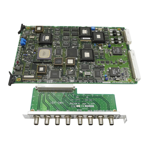
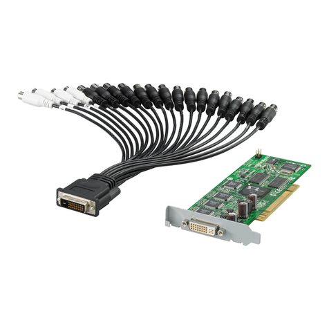
Sony BKSI-2050 User manual

BKSI-2050
ANALOG NTSC-4:2:2 CONVERTER BOARD
BKSI-2050P
ANALOG PAL-4:2:2 CONVERTER BOARD
INSTALLATION MANUAL
1st Edition (Revised 1)
Serial No.10001 and Higher (BKSI-2050)
Serial No.10001 and Higher (BKSI-2050P)

!WARNING
This manual is intended for qualified service personnel only.
To reduce the risk of electric shock, fire or injury, do not perform any servicing other than that
contained in the operating instructions unless you are qualified to do so.Refer all servicing to
qualified service personnel.
!WARNUNG
Die Anleitung ist nur für qualifiziertes Fachpersonal bestimmt.
Alle Wartungsarbeiten dürfen nur von qualifiziertem Fachpersonal ausgeführt werden.Um die
Gefahr eines elektrischen Schlages, Feuergefahr und Verletzungen zu vermeiden, sind bei
Wartungsarbeiten strikt die Angaben in der Anleitung zu befolgen. Andere als die angegeben
Wartungsarbeiten dürfen nur von Personen ausgeführt werden, die eine spezielle Befähigung
dazu besitzen.
!AVERTISSEMENT
Ce manual est destiné uniquement aux personnes compétentes en charge de l’entretien. Afin
de réduire les risques de décharge électrique, d’incendie ou de blessure n’effectuer que les
réparations indiquées dans le mode d’emploi à moins d’être qualifié pour en effectuer d’autres.
Pour toute réparation faire appel à une personne compétente uniquement.

1(E)
BKSI-2050/2050P
Table of Contents
Manual Structure
Purpose of this manual .............................................................................................. 2
Contents ..................................................................................................................... 2
Related manuals......................................................................................................... 2
Installation
1. Overview..........................................................................................................1-1
2. Installation of the Board ..................................................................................1-2
2-1. Plug-in Board Installation ................................................................1-2
2-2. Connector Panel Installation ............................................................1-3
3. Connection .......................................................................................................1-4
3-1. Location and Function of Connectors..............................................1-4
3-2. Connection Connector .....................................................................1-5
4. Location and Function of Switches/LEDs .......................................................1-6
5. Specifications...................................................................................................1-9
6. ISR .................................................................................................................1-10
6-1. Overview........................................................................................1-10
6-2. ISR Use Environment ....................................................................1-11
6-3. Commands .....................................................................................1-12

2(E) BKSI-2050/2050P
Purpose of this manual This manual is the installation manual of Analog NTSC - 4:2:2 Converter Board
BKSI-2050 and Analog PAL - 4:2:2 Converter Board BKSI-2050P.
This manual is intended for use by trained system and service engineers, and
describes the information when installing.
Contents This manual is organized by following sections.
1. Overview
This section describes the overviw of the BKSI-2050/2050P.
2. Installation of the Board
This section describes how to install the plag-in board and connector panel to the
System Interface Unit SIU-80.
3. Connecion
This section describes the location and function of connectors on the connector
panel and the matching connectors and cables.
4. location and Function of the Switches/LEDs
This section describes the location and function of the switches and LEDs on the
plug-in board, and setting at the factory.
5. Specifications
This section describes the specifications of BKSI-2050/2050P.
6. ISR
This section describes the overview of the ISR*1system.
*1:ISR (Interactive Status Reporting)
Status of this board or contents of errors occurred can be centralized to be monitored and managed on
the monitor screen of a personal computer.
Related manuals The following manual is prepared for this unit.
• Maintenance Manual (Optional manual)
This manual describes the information for periodic maintenance and detailed
service.
For obtaining the Maintenance Manual, please contact to your local Sony's sale/
service office.
Manual Structure

1-1(E)
BKSI-2050/2050P
1. Overview
The BKSI-2050 is the board that converts an analog composite video (NTSC) signal into a 4:2:2 compo-
nent serial digital video signal. The BKSI-2050P is the board that converts an analog composite video
(PAL) signal into a 4:2:2 component serial digital video signal.
When these boards are installed in system interface unit SIU-80, the analog composite video signal is
converted into a component serial digital video signal, distributed into four output signals, and finally
output.
n
This connector is not received the black-and-white signal, signal with jitter, and signal with unstable the
SCH.
The parts list of BKSI-2050/2050P is as follows.
BKSI-2050:ANALOG NTSC-4:2:2 CONVERTER BOARD
• Plug-in board (DEC-82 board) (1)
• Connector panel (CN-1216 board) (1)
• Installation guide (1)
• Installation manual (1)
• Model labels (2 sets)
BKSI-2050P:ANALOG PAL-4:2:2 CONVERTER BOARD
• Plug-in board (DEC-82P board) (1)
• Connector panel (CN-1216P board) (1)
• Installation guide (1)
• Installation manual (1)
• Model labels (2 sets)
Installation

1-2(E) BKSI-2050/2050P
2. Installatin of the Board
This section describes the installation procedures for the
front plug-in board and rear connector panel in a System
Interface Unit SIU-80.
For more details of each procedure, refer to the applicable
sections and Installation Manual supplied with SIU-80.
2-1. Plug-in Board Installation
Flow for installation
General information for installation
• The plug-in board is inserted into any slot No.1 to No.8
in the front of SIU-80.
• The model label supplied with the board is attached to the
shield plate to prevent the board inserting into the incor-
rect slot when the board replacement and others.
Procedures
1. Turn the SIU-80 power off and remove the front panel
and shield plate.
(Refer to the Installation Manual supplied with SIU-80.)
2. Set the switches on the board. (Refer to Section 4.)
3. Insert the board into a slot, and then turn the board levers
in the direction of the arrow 1and connect the board
securely to the connector of the SIU-80’s mother board.
4. Install the shield plate.
Then, attach the model label supplied with board on
the right side of the shield plate.
This label position should be aligned with the slot
installing the front panel.
5. Install the front panel.
6. Remove the board in the reverse order of steps 1
through 5.
n
When removing the board, turn the board levers in the
direction of the arrow 2, and pull the board out from
the slot.
1
2
1
212
Board lever Board lever
1Install
2Remove
SIU-80
Front panel
PSW 3×6
Shield plate
SIU-80
Model label
Start
Slot selection
Switch setting on board
Plug-in board installation (BKSI-2050/2050P:DEC-82/82P)
Model label attachment
End

1-3(E)
BKSI-2050/2050P
3. Attach the model label supplied with the connector
panel in the chassis near the slot to install the board.
n
After the connector panel is inserted into a slot, the
slot label cannot be viewd.
4. Insert the connector panel to the adaptive slot and fix
the panel with two screws securing the rear blank
panel.
5. Turn the SIU-80 power off and unplug the appliance
from the outlet, and remove the two screws installing
the connector panel and pull out it.
n
To remove the connector panel, move the right and left
handles on the connector panel front and back alter-
nately until the connection with the mother board is
sufficiently loose, then pull out the connector panel
gently.
2. Installatin of the Board
2-2. Connector Panel Installation
Flow for installation
General information for installation
• The connector panel is inserted into the same slot asthe
plug-in board installed in the front of SIU-80.
• The model label supplied with the connector panel is
attached to the chassis to prevent the panel inserting into
the incorrect slot when the connector panel replacement
and others.
w
For safety reason, turn off the power and unplug the
appliance from the outlet before starting the installation.
Installation procedures
1. Turn the SIU-80 power off and unplug the appliance
from the outlet.
2. Remove the rear blank pane.(Refer to the Installation
Manual supplied with the SIU-80.)
SIU-80
BVTT 3×6
Connector panel
Model label
Start
Slot selection
Connector panel installation
(BKSI-2050/2050P:CN1216/1216P)
Model label attachment
End
SIU-80
Rear blank panel
BVTT 3·6

1-4(E) BKSI-2050/2050P
3. Connection
NTSC-4:2:2
BKSI-2050
ANALOG IN
(NTSC) FRAME PULSE OUT
(TO BKSI-2070)
DIGITAL OUT
(4:2:2-SDI)
12 34
PAL-4:2:2
BKSI-2050P
ANALOG IN
(PAL) FRAME PULSE OUT
(TO BKSI-2070)
DIGITAL OUT
(4:2:2-SDI)
12 34
BKSI-2050P
BKSI-2050
12 3 4
3. Connection
3-1. Location and Function of Connectors
11
11
1ANALOG IN (analog signal input) connector (BNC type):
Received the analog composite video signal.
n
This connector is not received the black-and-white signal, signal with jitter, and signal with unstable
the SCH.
22
22
2Analog signal through out connector (BNC type):
Provided the signal with supplied to ANALOG IN connector, just as it is.
If not used this connector, connect a 75-ohm terminator.
33
33
3FRAME PULSE OUT (to BKSI-2070) connector (BNC type):
Provided the FRAME PULSE signal in synchronized with the digital video output signal.
Used the synchronized signal as the reference signal of optional Audio AD Converter Board BKSI-
2070.
44
44
4DIGITAL OUT (digital signal output) connectors (BNC type):
Converted the signal with provided to the ANALOG IN connector to the 4:2:2 component serial
digital signal.
The converted signal is synchronized with the reference signal and is provided when selecting into
the REF mode.
The converted signal is synchronized with the input signal and is provided when selecting into the
INPUT mode.
The minimum delay time between input and output is about 91.4 µs (about 1.5h) for NTSC model,
and is about 153.3 µs (about 2.5h) for PAL model during the INPUT mode. The same signals are
provided from these connectors 1 to 4.
If the input signal is not received when selecting into the INPUT mode, the 4:2:2 component serial
digital signal are not provided from these connectors.

1-5(E)
BKSI-2050/2050P
3. Connection
3-2. Connection Connector
If any cable is connected to the connectors on the connector panel when installing or servicing, use the
connector with listed below or equivalent.
BKSI-2050/2050P Matching Connector/Cable
Panel Indication Connector Connector/Cable Sony Part No.
ANALOG IN BNC 75ΩBNC 75Ω1-560-069-11
FRAME PULSE OUT BELDEN 8281 cable
DIGITAL OUT 1-4

1-6(E) BKSI-2050/2050P
4. Location and Function of Switches/LEDs
n
For the switches with described “Factory use only”, do
not change the settings.
11
11
1RV1: Input signal level control
Adjusted the level of the signal with provided to the
ANALOG IN connector.
In the adjustable range is ±3 dB.
Becomes possible to adjust when selecting the input
signal adjustment switch (S1) to the “MANUAL”.
22
22
2S1: Input signal adjustment switch
Selected the adjustment mode of signal with provided
to the ANALOG IN connector.
MANUAL : Adjusted the level of the input signal
by the input signal level control (RV1).
UNITY : Provided the input signal without
adjusting the level.
SYNC AGC : Automatically adjusted the level of the
input signal to the optimum value
relativing to the SYNC level of the
sync signal.
Factory setting : UNITY
33
33
3S2: SETUP REMOVE switch (BKSI-2050 Only)
Selected to remove the SETUP if or not when the
SETUP is added to the signal with provided to the
ANALOG IN connector.
The amount of the SETUP REMOVE is fixed to 7.5%.
OFF: Provided with the SETUP.
ON : Removed the SETUP (7.5%).
Factory setting : OFF
44
44
4S3: LOCK MODE switch
Selected the sync mode of the output signal.
REF : Provided the output signal in synchronized
with the reference signal. This mode is
operated as the frame synchronizer.
INPUT : Provided the output signal in synchronized
with the input signal.
The delay time between input and output is
minimum. The delay time is about 91.4 µs
(about 1.5h) for NTSC model and is about
153.3 µs (about 2.5h) for PAL model.
Factory setting : REF
55
55
5S4, S5 and RV2: SYSTEM H PHASE (system
phase) adjustment
Selected the delay time of the digital video output
signal in synchronized with the reference signal or
input signal.
The phase of the digital video output signal is the same
phase at the “80” when selecting into the REF mode
{when the LOCK MODE switch (S3) is selected to the
“REF”}, and is the minimum delay at the “00” when
selecting into the INPUT mode {when the LOCK-
MODE switch (S3) is selected to the “INPUT”}.
The delay time is about 91.4 µs (about 1.5h) for NTSC
model and is about 153.3 µs (about 2.5h) for PAL
model.
×16 (S4) : Sets the phase in units of about 592 ns.
Factory setting : 8
×1 (S5) : Sets the phase in units of about 37 ns.
Factory setting : 0
FINE (RV2) :Continuously adjusted the delay time in
the range from 0 to 37 ns.
66
66
6
D1: INPUT VIDEO (input video signal) indicator
Lights green; When the ANALOG IN connector is
received the analog video signal.
Lights red ; When not receiving the input signal or
when judging that the input signal is not
received.
4. Location and Function of Switches/LEDs
BKSI-2050
ON
OFF
RV1
S1
S2
S3
S4
S5
RV2
D1
D2
D4
S600S400
S200
S602 S601 S401
1
2
3
4
5
6
7
8
9
0
![ !- !\ !] !=
D3
ON
OFF
ON
OFF
: BKSI-2050 only

1-7(E)
BKSI-2050/2050P
!-!-
!-!-
!-
S400-1 and S400-2: SYSTEM V PHASE switches
Selected to the difference of output phase with the
reference video signal.
Only when selecting to the REF mode {when the
LOCK MODE switch (S3) is selected to the “REF”},
these switches are operated.
S400-1 S400-2 Output Phase
ON ON 2H advanced
ON OFF 1H advanced
OFF ON In-phase
OFF OFF 1H delayed
S400-3, S400-4, and S400-5: Blanking switches
Selected the optional line of the period between
vertical blanking to blank if or not.
[For NTSC model]
S400-3; OFF No blank.
S400-3; ON In the S400-4 and S400-5, the following
selections become possible.
S400-4 S400-5 Blanking Range
ON ON Odd field: Lines 10 to 20
Even field: First half of lines 273 to 283
ON OFF Odd field: Lines 10 to 21
Even field: First half of lines 273 to 284
OFF ON Odd field: Lines 10 to 20
Even field: Lines 273 to 283
OFF OFF Odd field: Lines 10 to 21
Even field: Lines 273 to 284
[For PAL model]
S400-3; OFF No blank.
S400-3: ON The odd field; Blank the first half of
lines 6 to 23.
The even field; Blank the lines 319 to
335.
The factory settings are shown below.
(The marks indicate the positions of the switch knobs.)
4. Location and Function of Switches/LEDs
ON
12345
77
77
7D2: REFERENCE (reference signal) indicator
Displayed the presence or absence of the reference
signal when selecting into the REF mode {when the
LOCK MODE switch (S3) is selected to the “REF”}.
Lights green; When the reference timing signal is
supplied from the SIU-80 to the DEC-
82/82P board.
Lights red; When the reference timing signal stops
to be providing.
Lights off; When selecting into the INPUT mode
{when the LOCK MODE switch (S3) is
selected to the “INPUT”}.
n
When the reference signal is not provided from the
outside, the SIU-80 is internally generated the free-run
reference signal and is provided the free-run reference
signal to the mother board. The unit is judged that the
reference signal is provided.
88
88
8D3: ERROR indicator
Lights red in the following cases.
• When the analog video signal is not provided to the
ANALOG IN connector or the unit is judged that
the analog video signal is not provided.
• When the reference timing signal is not generated
or the unit is judged that the reference timing signal
is not generated.
• When the signal is not provided from the DIGITAL
OUT connector.
• When an error occurs in the communication
between CPU and IC on the board.
99
99
9D4: FREEZE indicator
Lights green; With selected the auto freeze switch
(S601-1) to “ON”, when the input signal
is not generated and when the FREEZE
mode is selected.
00
00
0S200-1 and S200-2 (Factory use only)
Factory setting : Fixed to OFF.

1-8(E) BKSI-2050/2050P
4. Location and Function of Switches/LEDs
!\!\
!\!\
!\ S602: (Factory use only)
Factory setting : Fixed to all OFF.
!=!=
!=!=
!= S401-1: Free-running adjustment switch for
the parallel-serial conversion
Selected to the “ON” when free-running adjusting for
the parallel-serial conversion. (When selecting to the
“ON”, the SERIAL OUT is not provided.)
Factory setting : OFF
S401-2: (Factory use only)
Factory setting : Fixed to OFF.
![![
![![
![ S600: Microcomputer RESET switch
n
Under the normal operation, never press this switch.
!]!]
!]!]
!] S601-1: Auto freeze switch
Selected the auto freeze function that is automatically
selected into the FREEZE mode if the input signal is
not received.
Only when selecting into the REF mode {when the
LOCK MODE switch is selected to the “REF”}, the
selection of this switch become possible.
S601-3: Line operation setting switch
Selected the optional line of the vertical blanking into
the Y/C separation mode or B&W mode.
ON : Y/C separation mode
OFF : B&W mode
S601-5, S601-6, and S601-7:
Line setting switch for SETUP REMOTE
Selected the line that is removed the SETUP within the
vertical blanking period. (BKSI-2050 only.)
S601-7: ON Removed the SETUP of the lines 10 and
later of the odd field.
Removed the SETUP of the lines 273
and later of the even field.
S601-7: OFF Removed the SETUP of the lines with
selected at the switches S601-5 and S601-6.
S601-5 S601-6 Setup Remove Range
ON ON Odd field: Lines 22 and later
Even field: Lines 285 and later
ON OFF Odd field: Lines 22 and later
Even field: Lines 284 and later
OFF – Odd field: Lines 21 and later
Even field: The latter half of lines 283
and later
S601-2, S601-4, and S601-8: (Factory use only)
The factory settings are shown below.
(The marks indicate the positions of the switch knobs.)
12345678
ON

1-9(E)
BKSI-2050/2050P
5. Specifications
5. Specifications
General
Operating tempereture 5°C to 40°C (41°F to 104°F)
Storage tempereture –20°Cto 60°C (–4°F to +140°F)
Operating humidity 10 to 90 % (no condensation)
Dimensions Plug-in board : 283×347 mm(H/W) (111/4×133/4inches)
Connector panel : 301×112 mm(H/W) (12×41/2inches)
Mass Plug-in board : 1000 g (2 lb 3 oz)
Connector panel : 310 g (11 oz)
Power requirements +5 V dc :2300 mA
-5.2 V dc :440 mA
(supplied from SIU-80)
Power consumption 14 W
Input/output
Analog input ANALOG IN connector(BNC type) (1)
1.0 V p-p, 75 Ω
BKSI-2050 :NTSC analog composite video signal, with
loop-through output
BKSI-2050P :PAL analog composite video signal, with
loop-through output
Digital output DIGITAL OUT connector(BNC type) (4)
0.8 V p-p, 75 Ω
4:2:2 component serial digital video signal
Video characteristics
Sampling frequency
Input 14.318 MHz(NTSC), 17.734 MHz(PAL)
Output Y signal :13.5 MHz
R-Y, B-Y signals :6.75 MHz
Digitization bits 10 bits
Band width Y signal : 5.75 MHz
K factor(2T pulse) 1 % or less
Signal-to-noise ratio 58 dB or more
Y/C delay ±10 ns or less
Non-linearity 2 % or less
Design and specifications are subject to change without notice.

1-10(E) BKSI-2050/2050P
6. ISR
6. ISR
6-1. Overview
The BKSI-2050/2050P corresponds to a ISR(Interactive Status Reporting) function.
Using this function, the status of the BKSI-2050/2050P or the contents of a generated error can be
intensively monitored and managed on the monitor screen of a personal computer. The data displayed on
the monitor screen can be stored or printed as a file.
The major functions of the BKSI-2050/2050P are as follows.
Monitor functions
• Error message
Message Description
NO INPUT Indicates that no signal is input or the input signal is not judged to be contained.
NO REFERENCE Indicates that a reference timing signal is not supplied from SIU-80 for some reason.
However, this message is not displayed when the LOCK MODE switch (S3) is set to INPUT.
NO OUTPUT Indicates that the free-running adjustment switch of parallel-serial conversion (S401-1) is set
to ON.
NO BURST Indicates that no burst portion is contained in an analog input signal or the burst portion is
not judged to be contained.
PROCESS ERROR Indicates that the communication between the main CPU and each IC is possible on the
board.
n
It is possible to sellect from among three levels; ERROR, WARNING and DON’T CARE for each
message by using “SETUP ####;” command.
• Operation status
Message Status Display*1Description
INPUT GAIN UNITY Indicates the setting of the input signal adjustment switch (S1).
MANUAL
SYNC AGC
SYSTEM H PHASE [***] HEX Indicates the setting of the SYSTEM H PHASE (system phase)
adjustment switches (S4,S5) and control.
SYSTEM V PHASE 0H Indicates the setting of the SYSTEM V PHASE switches
1H DELAY (S400-1, S400-2).
1H ADVANCE When the LOCK MODE switch (S3) is selected to the “INPUT”,
2H ADVANCE displays “LOCKED TO INPUT” on the screen.
LOCKED TO INPUT
AUTO FREEZE OFF Indicates the setting of the Auto freeze switch(S601-1).
ON
LOCK MODE INPUT Indicates the setting of the LOCK MODE switch(S3).
REF
7.5 % SETUP REMOVE OFF Indicates the setting of the SETUP REMOVE switch (S2)
ON (BKSI-2050 Only).
*1: Status information displayed after the message. [***] indicates a variable.

1-11(E)
BKSI-2050/2050P
6. ISR
Management funcions
• Model name and slot number
• ROM version
• Error level selection(ERROR/WARNING/DON’T CARE)
Indicating item Description
Manufacturer Displayed as SONY.
Model Displays the model name.
Device ID Can give an arbitrary name to this board and register it.
VM sub-address Displays the address number (slot number +1) of SIU-80 in which this board is
inserted.
Destination Displays the destination. (BKSI-2050: UCJ, BKSI-2050P: CE)
ROM Displays the information of the ROM mounted on the board. (Board name, ROM
name, version, board address, and raw ROM name)
6-2. ISR Use Environment
The ISR function is controlled by Sony application program software. For the program software, use,
installation, and operation of a personal computer in which this program software can be used, consult
with your local Sony’s sale/service office.
The preparation below is required when managing the BKSI-2050 and BKSI-2050P by ISR.
1. Connect a personal computer to the RS-232C connector(D-sub 25-pin) of the SIU-80 which is
installed the BKSI-2050/2050P using a RS-232C cross cable.
2. Install the ISR application program software to the computer.
SIU-80 Personal computer
RS-232C Cross cable

1-12(E) BKSI-2050/2050P
6-3. Commands
BKSI-2050/2050P supports the following commands.
Command Support Support
*RST; O
*IDN?; O
*FLAGS?; O Only Power Cycled on
*STATUS?; O
*CMDERR?; O
*MSG?####; O
*UPLOAD?TYPE; O TYPE=VSETTBL
Response Support Support
*ATN : OPC; O
*ATN : CMDERR; O
*ATN : QRESP; O
SONY Private Command Support Support
SETUP?; O error level check
SETUP ##### ; parameter value O error level setting
DEVID;device-id O
6. ISR

The material contained in this manual consists of
information that is the property of Sony Corporation and
is intended solely for use by the purchasers of the
equipment described in this manual.
Sony Corporation expressly prohibits the duplication of
any portion of this manual or the use thereof for any
purpose other than the operation or maintenance of the
equipment described in this manual without the express
written permission of Sony Corporation.
Le matériel contenu dans ce manuel consiste en
informations qui sont la propriété de Sony Corporation et
sont destinées exclusivement à l’usage des acquéreurs
de l’équipement décrit dans ce manuel.
Sony Corporation interdit formellement la copie de
quelque partie que ce soit de ce manuel ou son emploi
pour tout autre but que des opérations ou entretiens de
l’équipement à moins d’une permission écrite de Sony
Corporation.
Das in dieser Anleitung enthaltene Material besteht aus
Informationen, die Eigentum der Sony Corporation sind,
und ausschließlich zum Gebrauch durch den Käufer der
in dieser Anleitung beschriebenen Ausrüstung bestimmt
sind.
Die Sony Corporation untersagt ausdrücklich die
Vervielfältigung jeglicher Teile dieser Anleitung oder den
Gebrauch derselben für irgendeinen anderen Zweck als
die Bedienung oder Wartung der in dieser Anleitung
beschriebenen Ausrüstung ohne ausdrückliche
schriftliche Erlaubnis der Sony Corporation.

Printed in Japan
Sony Corporation 1997. 6 16
Broadcast Products Company ©1995
Published by Broadcast Products Company
BKSI-2050P (CE)
BKSI-2050 (UCJ) J, E
3-189-229-02
This manual suits for next models
1
Table of contents
Other Sony Media Converter manuals

Sony
Sony DFR-E3000 User manual

Sony
Sony NXLK-IP50Y User manual

Sony
Sony HDRC-4000 User manual

Sony
Sony Ipela SNT-EX104 User manual

Sony
Sony BKSM-T103 User manual

Sony
Sony BKSM-R103 User manual

Sony
Sony VideoStore BKSR-2030 User manual

Sony
Sony TDM-NC1 - Wi-fi Client For Streaming Music User manual

Sony
Sony HAP User manual

Sony
Sony NU-NM11B Quick setup guide