Sperian Miller TechLine HLLR Series Operator's manual

1

2
TABLE OF CONTENTS
1.0 General Requirements (Warnings and Limitations).................................3-5
Warnings and Limitations
Lifeline
Capacity
Free Fall
Fall Clearance
Environmental Hazards
Connecting Devices
Anchor Points
Body Wear
2.0 Product Groups/System Compatibility.........................................................6
Anchor Point/Anchorage Connector
Body Wear
Connecting Devices
3.0 System Diagram and Description................................................................7
Tensioner
In-Line Shock Absorber
Cross-Arm Straps
Snaphook
Lifeline
O-Ring
4.0 Training and System Inspection...................................................................8
Training
Inspection
5.0 Set-up and Installation...........................................................................8-10
6.0 Fall Clearance......................................................................................10-11
Charts
Diagram
7.0 Care, Maintenance and Storage................................................................11
Cleaning Instructions
Maintenance/Service
Storage
8.0 Warranty Information.................................................................................12
Español......................................................................................................13-23
Français ....................................................................................................24-34
Product Labels/Étiquettes de Produit/Etiquetas del Producto............................35
USER INSTRUCTIONS - ENGLISH

3
THANK YOU
We would like to thank you for your purchase of Miller Fall Protection
equipment. Miller brand products are produced to meet the highest
standards of quality at our ISO 9001:2000 certied facility. They are
engineered to meet or exceed all applicable OSHA, ANSI, and CSA
testing requirements. Miller Fall Protection equipment will provide
you with years of use, if cared for properly.
1.0 GENERAL REQUIREMENTS
WARNINGS AND LIMITATIONS
• Warnings and instructions must be read and understood prior to using this
equipment. In addition, it is also the employer’s responsibility to ensure that all
users are trained in the proper use, inspection, and maintenance of fall protection
equipment. Fall protection training should be an integral part of a comprehensive
safety program.
• All users must reference applicable standard regulations governing occupational
safety.
• To minimize the potential for accidental disengagement, a competent person
must ensure system compatibility.
• All equipment must be visually inspected before each use.
• Equipment must not be altered in any way. Repairs must be performed only by
the equipment manufacturer, or persons or entities authorized, in writing, by the
manufacturer.
• Any product exhibiting deformities, unusual wear, or deterioration must be
immediately discarded.
• The user shall have a rescue plan and the means at hand to implement it when
using this equipment.
• This product is designed for personal fall protection. Never use fall protection
equipment for purposes other than those for which it was designed. Fall
protection equipment should never be used for towing or hoisting.
USER INSTRUCTIONS - ENGLISH
THIS DOCUMENT PROVIDES AN OVERVIEW OF FALL PROTECTION PRODUCTS
AVAILABLE FROM MILLER FALL PROTECTION AND CARE HAS BEEN TAKEN TO
ASSURE THE ACCURACY OF THE DATA. IT PROVIDES IMPORTANT PRODUCT
WARNINGS AND INSTRUCTIONS. MILLER FALL PROTECTION RECOMMENDS ALL
USERS OF FALL PROTECTION EQUIPMENT UNDERGO THOROUGH TRAINING, AND
THAT ALL WARNINGS AND INSTRUCTIONS PROVIDED WITH THE PRODUCTS BE
THOROUGHLY READ AND UNDERSTOOD PRIOR TO EACH USE. FAILURE TO READ
AND FOLLOW ALL PRODUCT WARNINGS AND INSTRUCTIONS COULD RESULT IN
SERIOUS INJURY OR DEATH.
WARNING

4
• Proper use of fall arrest systems can save lives and reduce the potential of
serious injuries from a fall. The user must be aware that forces experienced
during the arrest of a fall or prolonged suspension may cause bodily injury.
Consult a physician if there is any question about the user’s ability to use this
product. Pregnant women and minors must not use this product.
• Users should be familiar with pertinent regulations governing this equipment.
All individuals who use this product must be correctly instructed on how to use
the system and must read and understand the following instructions before use.
• Any equipment that has seen a fall must be removed from service.
LIFELINE
• Do not use this system if the tensioner does not lock onto the lifeline or if any
component in the system does not operate properly or appears to be damaged.
• Use only the lifeline provided.
• Work directly under or along side the lifeline to avoid hazards of a swing fall.
• The lifeline must be attached independently of the working surface.
• The lifeline must be placed at or above the back D-ring on harness.
CAPACITY
The maximum working load of Miller TechLine is two workers at 310 lbs (140.6kg)
each for the two-worker system. Do not exceed these weights. Refer to section 8.0
on individual fall protection system components for capacities.
FREE FALL
Personal fall arrest systems must be rigged to limit a free fall to the shortest possible
distance according to ANSI Z359.1 and ANSI A10.32 (6ft/1.8m maximum).
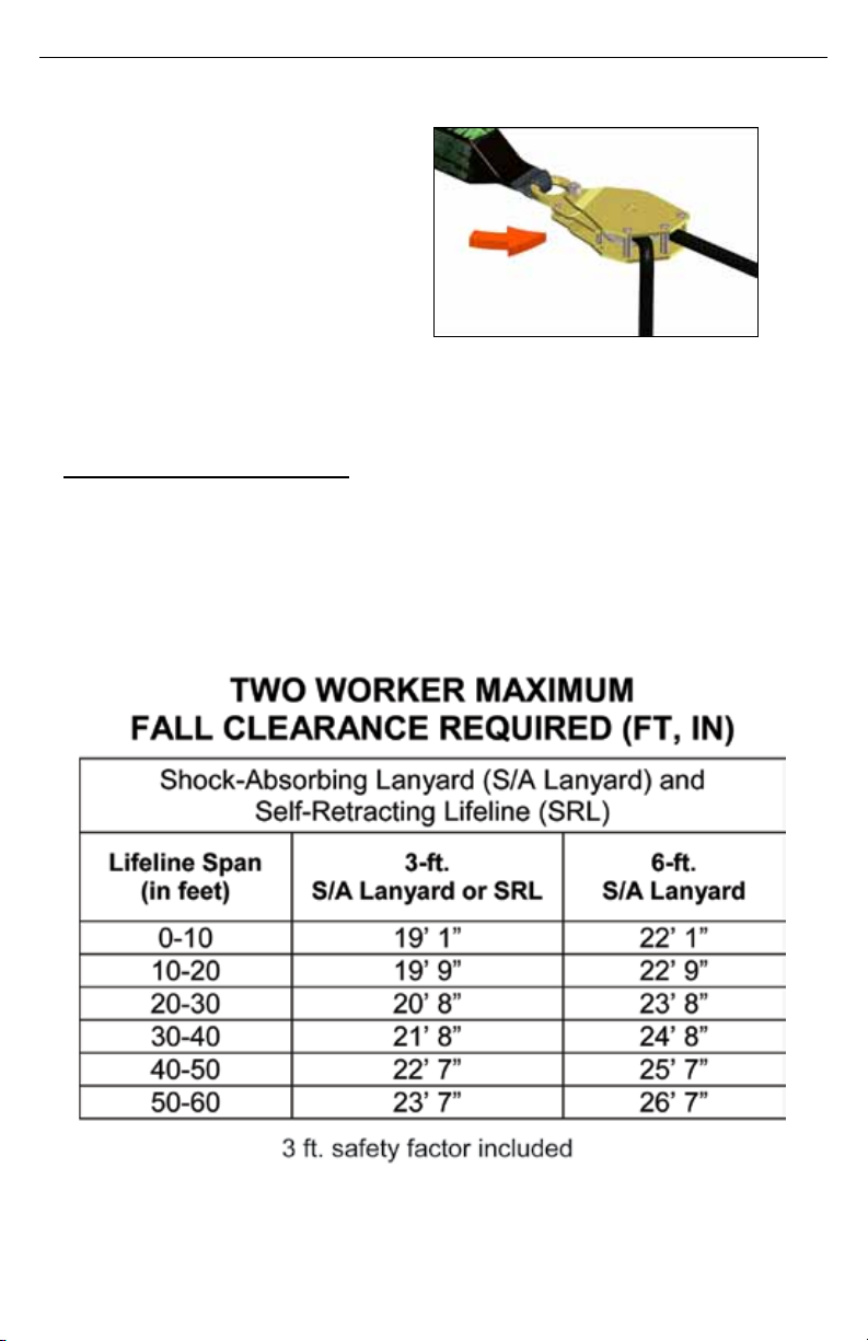
FALL CLEARANCE
Ensure that adequate clearance exists in your fall path to avoid striking an object.
The amount of clearance required is dependent upon the type of connecting
subsystem and anchorage location. Refer to section 6.0 on fall clearance for
capacities.
ENVIRONMENTAL HAZARDS
Use of this equipment in areas where environmental hazards exist may require
additional precautions to limit the possibility of injury to the user or damage to the
equipment. Hazards may include, but are not limited to high heat, caustic chemicals,
corrosive environments, high voltage power lines, explosive or toxic gases, moving
machinery, and sharp edges. Polyester should be used in certain chemical or acidic
environments. Consult the manufacturer in cases of doubt. All synthetic material
must be protected from slag, hot sparks, open ames, or other heat sources. The
use of heat resistant materials is recommended in these applications.
CONNECTING DEVICES
• A shock absorbing lanyard, self-retracting lifeline or other equipment specically
designed for fall arrest that has a maximum fall arrest force of 900 lbf (4kN) must
be used as a connecting device.
• Use only connecting devices with compatible locking snaphooks or auto-locking
carabiners.
USER INSTRUCTIONS - ENGLISH

5
• Always visually check that each snaphook and carabiner freely engages the
D-ring or anchor point, and that its keeper is completely closed and locked.
• Connect in a manner that limits free fall to the shortest possible distance
(6ft/1.8m maximum).
• Shock absorbers can elongate up to 3.5ft (1.07m). This maximum elongation
distance must be considered when choosing an anchorage point.
• Connect in a manner which ensures a lower level will not be struck should a fall
occur.
• Do not tie knots in lanyards.
• Never disable or restrict a locking keeper or alter connecting devices in any way.
• Do not attach multiple lanyards together, or attach a lanyard back onto itself unless
it is specically designed for that purpose.
• Do not wrap lanyards around sharp or rough edges. Use a cross-arm strap, tie
back lanyard or other compatible anchorage connector and connect to the back
D-ring of the harness.
• Do not allow rope or webbing to come in contact with high temperature surfaces,
welding, heat sources, electrical hazards, or moving machinery.
• Never use natural materials (manila, cotton, etc.) as part of a fall protection system.
• Make sure snaphook is positioned so that its keeper is never load bearing.
ANCHOR POINTS
• Anchor points must be capable of supporting 5000lbs (22kN).
• Always work directly under the anchor point to avoid a swing-fall injury.
• Never wrap lanyards around sharp or rough anchor points. Use a cross-arm strap
or other compatible anchorage connector to connect lanyard snaphook.
• Ensure that the anchor point is at a height that limits free-fall distance to 6ft (1.8m)
or less.
• Anchor point must be compatible with snaphook or carabiner and must not be
capable of causing a load to be applied to the keeper.
• Ensure that the anchor point is at a height that will not allow a lower level to be
struck should a fall occur.
• When selecting an anchorage point, always remember that shock absorbers may
elongate up to 3.5ft (1.07m).
• Never use an anchor point which will not allow snaphook or carabiner keeper to
close.
BODY WEAR
• Visually check all buckles to assure proper and secure connections before each
use.
• All straps must be connected and adjusted to provide a snug t.
• Fall protection connecting devices should be attached to the back D-ring of a full
body harness.
• Never attach non-locking snaps to a D-ring.
• Side, front and chest D-rings should be used for positioning only.
• Shoulder D-rings should be used for retrieval only.
USER INSTRUCTIONS - ENGLISH

6
A
B
C
USER INSTRUCTIONS - ENGLISH
2.0 PRODUCT GROUPS/SYSTEM COMPATIBILITY
A comprehensive fall protection program must be viewed as a “total system”
beginning with hazard identication and ending with ongoing management review.
Miller Fall Protection views its products as a “system within a system”. Three key
components of the “Miller System” need to be in place and properly used to provide
maximum worker protection.
The Miller TechLine Temporary Horizontal Lifeline System is designed for use with
Miller approved components. Substitution or replacement with non-approved
components will endanger the compatibility within the system and may affect
reliability and safety of the total system.
A. ANCHOR POINT/ANCHORAGE CONNECTOR
The rst component is the anchor point/anchorage connector. This point must
be capable of supporting 5,000lbs (22kN) per worker or meet OSHA 1926.502
requirements for a safety factor of 2, such as an I-beam or other support structure.
Anchorage connectors, such as cross-arm straps and eyebolts, are sometimes
necessary to make compatible connections between the connecting device and the
anchor point.
B. BODY WEAR
The second system component is the personal protective gear worn by workers
while performing the job. Miller Fall Protection manufactures full-body harnesses,
positioning belts and body belts for use in specic work environments. Full-body
harnesses are engineered to aid in the arrest of a free fall
and should be worn in all situations where workers are
exposed to a potential free fall. The full-body harness must
be used in conjunction with shock-absorbing equipment
to keep fall forces to a minimum. It is imperative that the
harness be worn properly.
C. CONNECTING DEVICES
The nal component of the system is the connecting device.
The most important feature of the connecting device is the
built-in shock-absorber. Whether the connecting device is
a shock-absorbing lanyard or self-retracting lifeline, they
are designed to dramatically reduce fall arresting forces.
Rope, web or cable lifelines being used for fall arrest MUST
be used in conjunction with a shock-absorber (i.e. Miller
SofStop pack.)
Individually, none of these components will provide
protection from a fall. Used properly with each other, they
form the “Miller System” and become a critically important
part of the “total fall protection system.”

7
3.0 SYSTEM DIAGRAM & DESCRIPTION OF COMPONENTS
(Complete system diagram shortened for illustrated purposes)
A. TENSIONER
Used to adjust the length of
the rope, indicate proper
pre-tension and maintain
tension. See section 5.0 for
proper use and set-up.
B. IN-LINE SHOCK
ABSORBER
Designed to limit forces to
2,500lbs. (11.2kN) which
provides a 2:1 safety
factor for 5,000lb (22.2kN)
anchorage.
C. CROSS-ARM
STRAPS
Used to secure lifeline to
anchorage point.
D. SNAPHOOK
Self-locking snaphook used to
connect the ends of the lifeline to an
approved anchorage connector.
E. LIFELINE
11/16 in. (17.5mm) static kernmantle
rope used to span between two an-
chorage connectors.
F. O-RING
Used to connect worker’s shock
absorbing lanyard or self-retracting
lifeline to the horizontal lifeline.
B- In-Line Shock
Absorber
A- Tensioner
C- Cross-Arm Straps
USER INSTRUCTIONS - ENGLISH
CC
DE
F
D
A
B
F- O-Rings
D- Snaphook
E- Lifeline

8
4.0 TRAINING AND SYSTEM INSPECTION
TRAINING
It is the responsibility of the user and the purchaser of this equipment to assure they
are familiar with these instructions and are trained in the proper use, installation,
operation, maintenance and limitations of this product. Training should be conducted
periodically and without exposing the trainee to a fall hazard.
Training is an integral part of our Total Solution in fall protection, since no fall
protection equipment – regardless of how effective – can save an employee who
is not trained in its use. To meet this crucial requirement, Miller Training provides
the knowledge and skills necessary to achieve a safe, more productive work envi-
ronment. For more information on Miller Training, contact a representative today:
800.873.5242
INSPECTION
Before each use, visually inspect for the following:
• Inspect for physical damages, wear and corrosion.
• Check tensioner for damage, crack, wear, corrosion or malfunctioning components.
• Inspect lifeline and anchorage line for cuts, frays, burns and broken bers.
• For any missing, damaged or replacement parts call: 800.873.5242
• IfInspectionrevealsadefectinconditionorhasseenafall,removetheunits
fromservice.
TYPES OF MATERIAL DAMAGE
5.0 SET-UP AND INSTALLATION
Before installation of this equipment, carefully inspect to assure that it is in useable
condition. Check for missing or damaged parts. If any parts are missing or damaged,
contact Miller Fall Protection before proceeding.
Anchorage connectors must be rated for 5,000 lbs (22.2KN) and chosen to locate
lifeline at or above the height of the D-ring on harness. See section 3.0 for diagram
and description reference. For proper set-up prior to use, follow steps 1-5.
USER INSTRUCTIONS - ENGLISH
HEAT CHEMICAL
POLYESTER
MOLTEN
METAL OR
FLAME
PAINTS AND
SOLVENTS
Paint which penetrates
and dries restricts
movement of bers.
Drying agents and
solvents in some
paints will appear as
chemical damage.
In excessive heat,
polyester becomes
brittle and has a
shriveled brownish
appearance. Fibers
will break when
exed. Should not be
used above 180°F.
Change in color
usually appearing as
a brownish smear or
smudge. Transverse
cracks when rope/
webbing is bent over
a mandrel. Loss of
elasticity in rope/
webbing.
Rope/webbing strands
fuse together. Hard
shiny spots. Hard and
brittle feel.

9
USER INSTRUCTIONS - ENGLISH
Step 1
Wrap cross-arm strap around
approved anchorage point. To
prevent slippage, wrap cross-
arm strap around anchorage
point as many times as possible.
D-ringmustpasscompletely
throughloop.
Step 2
Secure snaphooks on either
end of lifeline to D-ring
on cross-arm straps. Be
sure snaphook is attached
properly and no gate loading
is present.
Step 4
Tension the line with wrench
or bar by pulling rmly on the
free end of the rope while
at the same time turning the
tensioner nut in the direction
of the arrow. Tighten nut
until tensioner begins to
slip against the rope. Once
slippageoccurs,DONOT
continuetotightenthe
tensioner.
Step 3
Remove slack in system by
releasing the tension release
lever and pull the free end of
the rope through the tensioner.

10
USER INSTRUCTIONS - ENGLISH
6.0 FALL CLEARANCE
Step 5
Close the tension
release lever to prevent
unintentional loosening
of line tension.
FALL CLEARANCE CHARTS
Refer to the following tables and “Total Fall Clearance Required” in the Fall Clearance
Diagram to determine minimum required clearance from lifeline to surface or obstruction.

11
USER INSTRUCTIONS - ENGLISH
7.0 CARE, MAINTENANCE AND STORAGE
CLEANING INSTRUCTIONS
Basic care of all Miller Fall Protection equipment will prolong the life of the unit and
will contribute toward the performance of its vital safety function. Proper storage and
maintenance after use are as important as cleansing the equipment of dirt, corrosives,
or contaminants. Storage areas should be clean, dry and free of exposure to fumes or
corrosive elements. Wipe off all surface dirt with a sponge dampened in plain water.
Squeeze the sponge dry. Dip the sponge in a mild solution of water and commercial
soap or detergent. Work up a thick lather, with a vigorous back and forth motion. Then
wipe dry with a clean cloth. Hang freely to dry, but away from excessive heat or steam.
MAINTENANCE/SERVICE
Servicing must only be carried out by a qualied person trained in the inspection
and replacement of the system. A record log of all servicing and inspection dates for
this system should be maintained by the company safety ofcer. This system and all
components must be withdrawn from service if subjected to fall arresting forces. Only
original Miller Fall Protection replacement parts are approved for use in this device.
Contact your Miller Fall Protection distributor or Miller Fall Protection Technical Service
department at 800.873.5242 if you have any questions.
STORAGE
Clean the components to remove any dirt, paint or other materials that may have
accumulated. Store in a clean, dry area when not in use.
Lower Level
Fall-Clearance
From Working
Surface To Next
Surface
System Height
Above Working
5
FT To
Worker's
D-Ring
3
FT
Safety Factor
Deflection
HLL
Lanyard Length
3.5
FT Lanyard
Deployment
Clearance Required
Total Fall-
1
FT Harness Stretch
6
FT
Worker
Height
FALL CLEARANCE DIAGRAM

12
8.0 WARRANTY INFORMATION
MILLER®FALL PROTECTION PRODUCTS
TOTAL SATISFACTION ASSURANCE
At Miller Fall Protection, We have been providing quality Miller brand fall protection
equipment to millions of workers worldwide since 1945.
LIMITED LIFETIME WARRANTY
BACKEDBYOVER60YEARSINTHEFALLPROTECTIONBUSINESS
We sincerely believe that our fall protection equipment is the best in the world.
Our products endure rigorous tests to ensure that the fall protection equipment you trust
is manufactured to the highest standards. Miller fall protection products are tested to
withstand normal wear and tear, but are not indestructible and can be damaged by
misuse. Our Limited Lifetime Warranty does not apply to normal wear and tear or
abusive treatment of the product.
In the unlikely event that you should discover defects in either workmanship or
materials, under our Limited Lifetime Warranty, we will repair or replace the product at
our expense. If a replacement is necessary and your product is no longer available, a
comparable product will be substituted. Should a product issue surface,
contact us at 800.873.5242.
Manufacturing specications are subject to change without notice.
Toll Free 800.873.5242 Fax 800.892.4078
Phone: 814.432.2118 Fax 814.432.2415
USER INSTRUCTIONS - ENGLISH

Instrucciones Para El Usuario - Español
13
ÍNDICE
1.0 Requisitos generales (advertencias y limitaciones).............................14-17
Advertencias y limitaciones
Cuerda salvavidas
Capacidad
Caída libre
Distancia segura de caída
Peligros ambientales
Dispositivos de conexión
Puntos de anclaje
Aparejo
2.0 Grupos de productos/Compatibilidad del sistema.....................................17
Punto de anclaje/conector de anclaje
Aparejo
Dispositivos de conexión
3.0 Diagrama y descripción del sistema..........................................................18
Tensor
Amortiguador de impacto en línea
Correas para travesaños
Gancho de resorte
Cuerda salvavidas
Anillos redondos
4.0 Capacitación e inspección del sistema.....................................................19
Capacitación
Inspección
5.0 Montaje e instalación...........................................................................19-21
6.0 Distancia segura de caída....................................................................21-22
Tablas
Diagrama
7.0 Cuidado, mantenimiento y almacenaje.....................................................22
Instrucciones de limpieza
Mantenimiento/servicio
Almacenamiento
8.0 Información para la garantía.....................................................................23

Instrucciones Para El Usuario - Español
14
Gracias
Le agradecemos que haya adquirido un equipo anticaídas Miller. Los
productos de la marca Miller son manufacturados para cumplir con los más
altos estándares de calidad en nuestra fábrica, que posee la certicación
ISO 9001:2000. Han sido diseñados para que cumplan o superen todos
requisitos de pruebas aplicables establecidos por OSHA, ANSI y CSA. Cui-
dados como es debido, los equipos anticaídas Miller le servirán muchos
años.
1.0 Requisitos Generales
Advertencias Y Limitaciones
• Es preciso leer y entender las advertencias e instrucciones antes de usar este
equipo. Además, también es responsabilidad del empleador que todos los
usuarios hayan recibido capacitación para usar, inspeccionar y dar el debido
mantenimiento al equipo anticaídas. La capacitación anticaídas debe ser parte
integral de un completo programa de seguridad.
• Todos los usuarios deben remitirse a las regulaciones y normas de seguridad
laboral.
• A n de reducir al mínimo las posibilidades de un desenganche accidental, una
persona competente debe garantizar la compatibilidad del sistema.
• Todos los equipos deben ser inspeccionados visualmente antes de cada uso.
• Los equipos no deben sufrir ningún tipo de alteración. Las reparaciones deben
ser efectuadas exclusivamente por el fabricante del equipo o bien por perso-
nas o entidades autorizadas por escrito por el fabricante.
• Todo producto con señales de deformación, desgaste inusual o deterioro debe
ser puesto fuera de servicio de inmediato.
• El usuario debe contar con un plan y medios de rescate a mano a objeto de
poderlos aplicar cuando se usa este equipo.
• Este producto ha sido diseñado para protección anticaídas personal. Jamás lo
utilice para nes distintos al diseñado. No use jamás el equipo para remolcar o
izar objetos.
En Este Documento Se Suministra Una Vista General De Los Productos
Anticaídas Ofrecidos Por Miller Fall Protection, Y Se Ha Tenido El Debido
Cuidado Para Garantizar La Certeza De La Información. Provee Adverten-
cias E Instrucciones Importantes De Los Productos. Miller Fall Protection
Recomienda A Todos Los Usuarios De Equipos Anticaídas Someterse A
Una Capacitación Completa, Así Como Leer Y Comprender Todos Los Avi-
sos De Advertencia E Instrucciones Suministrados Con Los Productos. SI
No Se Leen Y Respetan Todas Las Advertencias E Instrucciones Podrían
Producirse Lesiones Serias Y Hasta Fatales.
ADVERTENCIA

Instrucciones Para El Usuario - Español
15
• La utilización correcta de los sistemas anticaídas puede salvar vidas y dis-
minuir las posibilidades de lesiones graves en caso de una caída. Los usuarios
deben estar conscientes de que las fuerzas ejercidas para detener una caída
o durante una suspensión prolongada pueden causar lesiones. Consulte a un
médico en caso de duda sobre la capacidad del usuario para emplear este
producto. Las mujeres embarazadas y los niños no deben usar este producto.
• Los usuarios deberán estar familiarizados con las regulaciones pertinentes
relativas a este equipo. Toda persona que use este producto deberá ser cor-
rectamente instruida sobre cómo usar el sistema y deberá leer y entender las
siguientes instrucciones previamente.
• Todo equipo sometido a una caída debe ser puesto fuera de servicio.
CUERDA SALVAVIDAS
• No use este sistema si el tensor no se traba en la cuerda salvavidas o si algún
componente del sistema no funciona correctamente o parece estar dañado.
• Use solo la cuerda salvavidas de provista.
• Trabaje directamente bajo o al lado de la cuerda salvavidas para evitar los
peligros de una caída columpiada.
• La cuerda salvavidas se debe sujetar de manera independiente a la supercie de trabajo.
• La cuerda salvavidas se debe colocar encima o arriba del anillo D trasero del arnés.
CAPACIDAD
La carga de trabajo máxima de Miller TechLine es dos trabajadores de 310 lb
(140.6 kg) cada uno para el sistema de dos personas. No supere estos pesos.
Consulte en la sección 8.0 la capacidad de los componentes individuales del
sistema anticaídas.
CAÍDA LIBRE
Los sistemas personales de detención de caídas deben estar aparejados de tal
manera que limiten una caída libre a la menor distancia posible, a 6 pies (1.8 m)
(según ANSI Z359.1 y ANSI A10.32).
DISTANCIA SEGURA DE CAÍDA
Verique que hay una distancia segura adecuada en la trayectoria de caída para
no impactar contra algún objeto. La distancia segura de caída depende del tipo de
subsistema de conexión y de la ubicación del anclaje. Consulte las capacidades en
la sección 6.0 sobre distancia de segura de caída.
PELIGROS AMBIENTALES
Cuando se use este equipo en áreas con riesgos ambientales, se podrían requerir
precauciones adicionales a objeto de limitar la posibilidad de lesiones al usuario o
daños al equipo. Entre los riesgos se puede incluir, entre otros, temperaturas eleva-
das, productos químicos cáusticos, ambientes corrosivos, líneas de alta tensión,
gases explosivos o tóxicos, maquinaria en movimiento y bordes alados. En ciertos
ambientes con presencia de determinados agentes químicos o ácidos se deberá
usar poliéster. En caso de duda, consulte al fabricante. Se deberá proteger todo
el material sintético a objeto de mantenerlo alejado de escorias, chispas calientes,
llamas y otras fuentes de calor. Para tales aplicaciones, se recomienda el uso de
materiales resistentes al calor.

Instrucciones Para El Usuario - Español
16
DISPOSITIVOS DE CONEXIÓN
• Como dispositivo de conexión se debe usar una cuerda de seguridad con am-
ortiguación de impacto, una cuerda salvavidas retráctil u otro equipo diseñado
especícamente para detención de caídas, con una fuerza máxima de deten-
ción de caída de 408 kgf (900 lbf).
• Use exclusivamente dispositivos de conexión con ganchos de resorte o
mosquetones de autoaseguramiento compatibles.
• Siempre inspeccione visualmente que cada gancho de resorte y mosquetón
se enganche sin problemas al anillo “D” o al punto de anclaje y que el linguete
esté perfectamente cerrado y trabado.
• Conecte de manera tal que la caída libre se limite a la menor distancia posible
(6 pies/1.8 m máximo).
• Los amortiguadores de impacto pueden alargarse hasta 3.5 pies (1.07 m). Es
menester tener en cuenta este alargamiento a la hora de seleccionar un punto de
anclaje.
• Conecte de manera tal que evite impactar contra un nivel inferior en caso de caída.
• No haga nudos en la cuerda de seguridad.
• Jamás inutilice ni restrinja un linguete de aseguramiento ni modique en modo
alguno los dispositivos de conexión.
• No conecte varias cuerdas de seguridad entre sí, ni conecte una cuerda de
seguridad a sí misma, salvo que esté especícamente diseñada para tal n.
• No enrolle las cuerdas de seguridad alrededor de bordes alados o rugosos.
Use una correa para travesaños, una cuerda de seguridad de amarre posterior
u otro conector de anclaje compatible y conecte a la parte posterior del anillo
“D” del arnés.
• No permita que la cuerda ni el tejido hagan contacto con supercies de alta
temperatura, soldaduras, fuentes de calor, peligros eléctricos ni maquinarias en
movimiento.
• Jamás use materiales naturales (cáñamo de Manila, algodón, etc.) como parte
de un sistema de protección contra caídas.
• Verique que el gancho de resorte no someta a cargas el linguete.
PUNTOS DE ANCLAJE
• Los puntos de anclaje deben resistir 5000 lb (22 kN).
• Siempre trabaje directamente bajo el punto de anclaje para evitar una lesión
por caída columpiada.
• Jamás enrolle las cuerdas de seguridad alrededor de puntos de anclaje a-
lados o rugosos. Use una correa para travesaños u otro conector de anclaje
compatible para conectar el gancho de resorte de la cuerda de seguridad.
• Verique que la altura del punto de anclaje limite la distancia de caída libre a 6 pies
(1.8 m) o menos.
• El punto de anclaje debe ser compatible con el gancho de resorte o mosquetón, y
no debe aplicar ninguna carga en el linguete.
• Verique que el punto de anclaje se encuentre a una altura tal que, en caso de una
caída, no haga impacto en un nivel inferior.
• Al seleccionar un punto de anclaje, siempre recuerde que los amortiguadores de
impacto pueden estirarse hasta 3.5 pies (1.07 m).
• Jamás use un punto de anclaje que impida el cierre del gancho de resorte o del
mosquetón.

Instrucciones Para El Usuario - Español
17
A
B
C
APAREJO
• Verique visualmente todas las hebillas para tener certeza de que las conexiones
están bien y son seguras antes de cada uso.
• Todas las correas deben estar conectadas y ajustadas para que provean un ajuste apretado.
• Los dispositivos de conexión de protección anticaídas deberán estar conectados al
anillo “D" situado en parte posterior de un arnés de cuerpo entero.
• Jamás conecte aseguradores sin traba a un anillo “D”.
• Los anillos “D” laterales, frontales y de pecho sólo se deben usar para posicionamiento.
• Los anillos “D” para los hombros se deben usar exclusivamente para recogida.
2.0 GRUPOS DE PRODUCTOS/COMPATIBILIDAD DEL SISTEMA
Un programa integral anticaídas debe ser visto como un “sistema total” que comienza con
la identicación y culmina con la revisión gerencial en curso. Miller Fall Protection considera
sus productos como “un sistema dentro de un sistema”. Tres componentes principales del
“sistema Miller” deben estar en su lugar y usarse debidamente para que puedan proporcio-
nar la máxima protección al trabajador.
El sistema de cuerda salvavidas horizontal temporal Miller TechLine se diseñó para usar
con componentes aprobados por Miller. La sustitución o reemplazo con combinaciones no
aprobadas de componentes o subsistemas pondrá en peligro la compatibilidad dentro del
sistema y puede afectar la abilidad y seguridad del sistema en su totalidad.
A. PUNTO DE ANCLAJE/CONECTOR DE ANCLAJE
El primer componente es el punto de anclaje/conector de anclaje. Este punto debe ser ca-
paz de resistir 5000 lb (22 kN) por trabajador o cumplir con los requisitos de la norma OSHA
1926.502 para un factor de seguridad de dos (2), como los de una viga “I” u otra estructura
portante. A veces se requieren conectores de anclaje, por ejemplo, correas para travesa-
ños y pernos de argolla, para que las conexiones sean compatibles entre el dispositivo de
conexión y el punto de anclaje.
B. APAREJO
El segundo componente del sistema es el equipo de protec-
ción personal usado por los trabajadores mientras realizan su
labor. Miller Fall Protection fabrica arneses de cuerpo entero,
cinturones de posicionamiento y cinturones para entornos
de trabajo especícos. Los arneses de cuerpo entero están
diseñados para contribuir a la parada de una caída libre y se
deben usar siempre que el trabajador esté expuesto a una
posible caída libre. Para reducir al mínimo las fuerzas de la
caída, el arnés de cuerpo entero se debe usar conjuntamente
con un equipo amortiguador de impacto. Es imperativo usar el
arnés como es debido.
C. DISPOSITIVOS DE CONEXIÓN
El último componente del sistema es el dispositivo de conex-
ión. La característica más importante del dispositivo de conex-
ión es el amortiguador de impacto incorporado. Independiente-
mente de que dicho dispositivo sea una cuerda de seguridad
con amortiguador de impacto o una cuerda salvavidas retráctil,
ambas están diseñadas para reducir de manera impresionante
las fuerzas ejercidas para detener la caída. Las cuerdas salvavidas comunes, tejidas o de
cable usadas para la detención de caídas SE DEBEN usar conjuntamente con un amor-
tiguador de impacto (por ejemplo, el paquete Miller SofStop).
De manera individual, ninguno de estos componentes ofrece protección contra una caída.
Usados en conjunto como es debido, conforman el “sistema Miller” y se convierten en una
parte de vital importancia del “sistema completo de protección contra caídas”.

Instrucciones Para El Usuario - Español
18
3.0 DIAGRAMA DEL SISTEMA Y DESCRIPCIÓN DE COMPONENTES
(Se ha abreviado el diagrama del sistema completo para nes ilustrativos)
A. TENSOR
Se usa para ajustar la longitud
de la cuerda, indicar la debida
pre-tensión y mantener la
tensión. Vea en la sección
5.0 las instrucciones de uso y
montaje correctos.
B. AMORTIGUADOR DE
IMPACTO EN LÍNEA
Fabricado para limitar fuerzas
hasta de 2,500 lb (11.2 kN)
lo cual proporciona un factor
de seguridad de 2:1 para un
anclaje de 5,000 lb (22.2 kN).
C. CORREAS PARA
TRAVESAÑOS
Se usan para asegurar la
cuerda salvavidas al punto de
anclaje.
D. GANCHO DE RESORTE
El gancho de resorte de asegu-
ramiento automático se emplea
para conectar los extremos de la
cuerda salvavidas a un conector
de anclaje aprobado.
E. CUERDA SALVAVIDAS
Correa tejida de kernmantle
estático de 11/16 pulg. (17.5 mm)
usada para cubrir la distancia
entre dos conectores de anclaje.
F. ANILLO REDONDO
Se emplea para conectar la
cuerda de seguridad con
absorción de impacto o la cuerda
salvavidas retráctil a la cuerda
salvavidas horizontal.
CC
DE
F
D
A
B
B- Amortiguador
de impacto en línea
A- Tensor
C- Correas para
travesaños
F- Anillos
redondos
D- Gancho de
resorte
E- Cuerda salvavidas

Instrucciones Para El Usuario - Español
19
4.0 CAPACITACIÓN E INSPECCIÓN DEL SISTEMA
CAPACITACIÓN
Es responsabilidad del usuario y de quien adquiere este equipo familiarizarse con el uso
correcto, la instalación, operación, mantenimiento y las limitaciones de este producto. Se
deberán realizar capacitaciones periódicas, sin exponer a la persona en capacitación a
peligros de caídas.
La capacitación es parte integral de nuestra Solución Total en protección anticaídas, ya
que ningún equipo de protección contra caídas, independientemente de su efectividad,
puede salvar a un empleado sin capacitación para usarlo. Para cumplir este requisito
crucial, Miller Training provee el conocimiento y las destrezas necesarias para lograr un
ambiente de trabajo seguro y más productivo. Si desea más información sobre el pro-
grama de capacitación Miller Training, contacte hoy a un representante: 800.873.5242
INSPECCIÓN
Antes de cada uso, inspecciones visualmente lo siguiente:
• Daños físicos, desgaste y corrosión.
• Revise el tensor, para ver si no hay daños, grietas, desgaste, corrosión o componen-
tes en mal funcionamiento.
• Inspeccione la cuerda salvavidas y la línea de anclaje para ver si no tienen cortes,
quemaduras, bras rotas o raídas.
• Si le faltara alguna pieza, estuviera dañada o necesitara un repuesto, llame al:
800.873.5242
• Si la inspección revela un defecto en el estado o se ha observado una caída, ponga
las unidades fuera de servicio.
TIPOS DE DAÑOS DEL MATERIAL
CALOR
SUSTANCIAS
QUÍMICAS
POLIÉSTER
METAL
FUNDIDO O
LLAMA
PINTURAS Y
SOLVENTES
La pintura que penetra
y se seca, restringe
el movimiento de las
bras. Los agentes de
secado y solventes
de algunas pinturas
lucirán como daño de
sustancias químicas.
Sometido a calor
excesivo, el poliéster se
vuelve quebradizo, tiene
aspecto apergaminado
y tono amarronado. Las
bras se partirán al ser
exionadas. No debe
usarse a temperaturas
superiores de 180°F
(82ºC).
Se producen un
cambio de color, por lo
general aparece como
una mancha o borrón
amarronado. Grietas
transversales cuando la
cuerda o correa tejida
se enrolla en un mandril.
Pérdida de elasticidad en
la cuerda/correa tejida.
Las hebras de la
cuerda/del tejido se
fusionan entre sí.
Puntos brillantes
duros. Duros y
quebradizos al tacto.
5.0 MONTAJE E INSTALACIÓN
Antes de instalar el equipo, inspecciónelo cuidadosamente para vericar que se encuentra
en condiciones de ser usado. Verique que no haya partes faltantes o deterioradas. En tal
caso, contacte a Miller Fall Protection antes de seguir.
Los conectores de anclaje deben ser aptos para 5,000 lb (22.2 KN) y se elegirán para
ubicar la cuerda salvavidas sobre o arriba de la altura del anillo D del arnés. Consulte el
diagrama y la referencia descriptiva en la sección 3.0. Para el montaje correcto antes del
uso, siga los pasos 1-5.
3.0 DIAGRAMA DEL SISTEMA Y DESCRIPCIÓN DE COMPONENTES
(Se ha abreviado el diagrama del sistema completo para nes ilustrativos)

Instrucciones Para El Usuario - Español
20
Paso 1
Enrolle la correa para travesaños
alrededor del punto de anclaje. Para
prevenir resbalamiento, enrolle esta
correa alrededor del punto de anclaje
cuantas veces sea posible. ElanilloD
debepasarcompletamenteatravés
delalazada.
Paso 2
Fije los ganchos de resorte en cada ex-
tremo de la cuerda salvavidas al anillo
D sobre las correas para travesaños.
Asegúrese de que el gancho de resorte
esté debidamente colocado y que no
esté sometido a carga alguna.
Paso 3
Elimine la holgura del sistema soltando
la palanca para aliviar la tensión y jale
el extremo libre de la cuerda a través
del tensor.
Paso 4
Aplique tensión a la línea con una llave
o barra, halando con rmeza sobre el
extremo libre de la cuerda y al mismo
tiempo se gira la tuerca del tensor en
dirección de la echa. Apriete la tuerca
hasta que el tensor comience a desli-
zarse contra la cuerda. Tanpronto
comocomienceadeslizarse,NO
SIGAajustandoeltensor.
Table of contents
Languages:
Other Sperian Safety Equipment manuals

Sperian
Sperian Miller Bosuns Chair User manual

Sperian
Sperian MILLER M1070007 User manual

Sperian
Sperian MILLER Grip 497 Guide

Sperian
Sperian Miller Turbo T-BAK User manual

Sperian
Sperian Miller ARL-100-Z7/8FT Operator's manual

Sperian
Sperian Miller 1007031 Operating instructions

Sperian
Sperian WARRIOR User manual

Sperian
Sperian SPERIAN Warrior SCBA Troubleshooting guide

Sperian
Sperian Miller FALCON Series Instruction manual

Sperian
Sperian Miller EN 360 User manual