Suplemento del manual de instrucciones para el usuario - Español
10
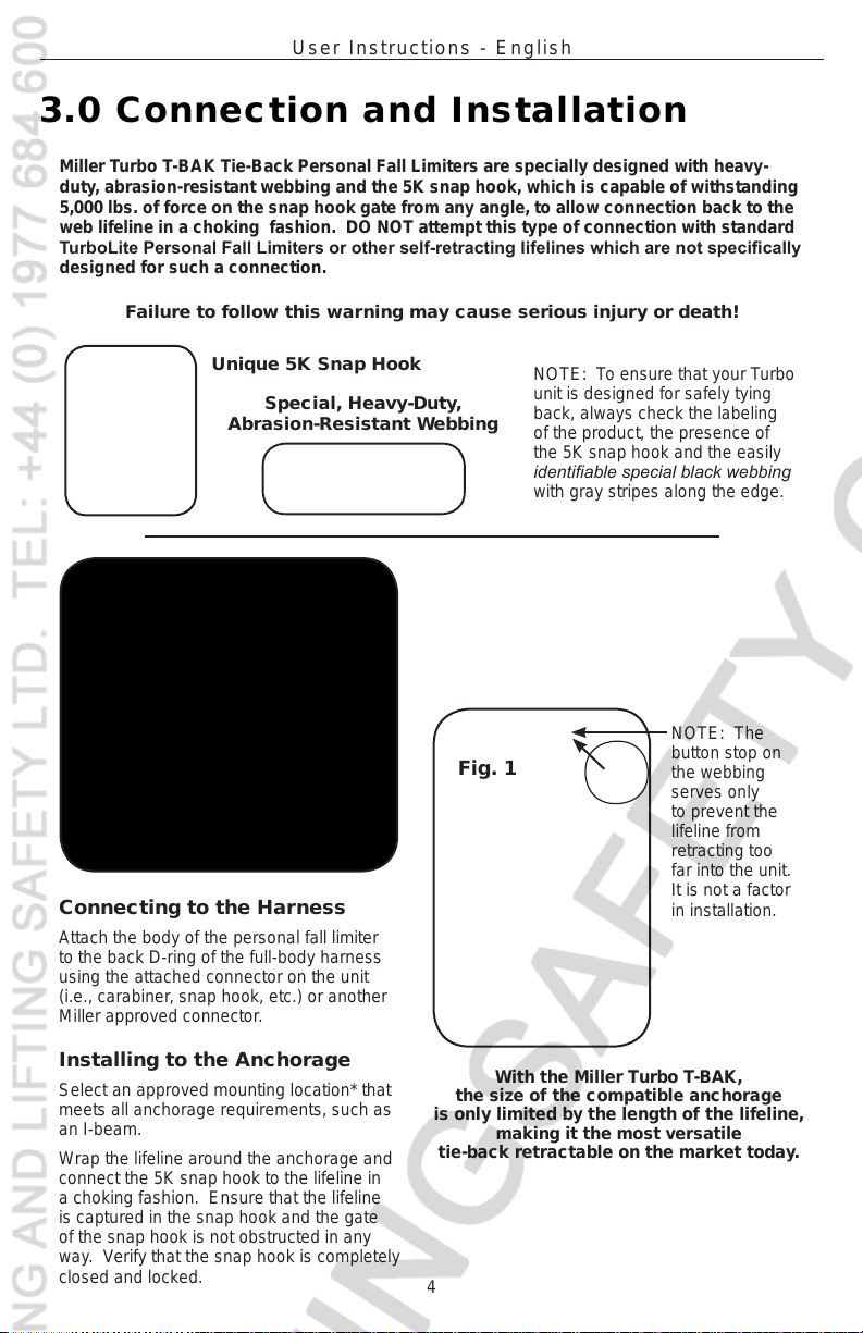
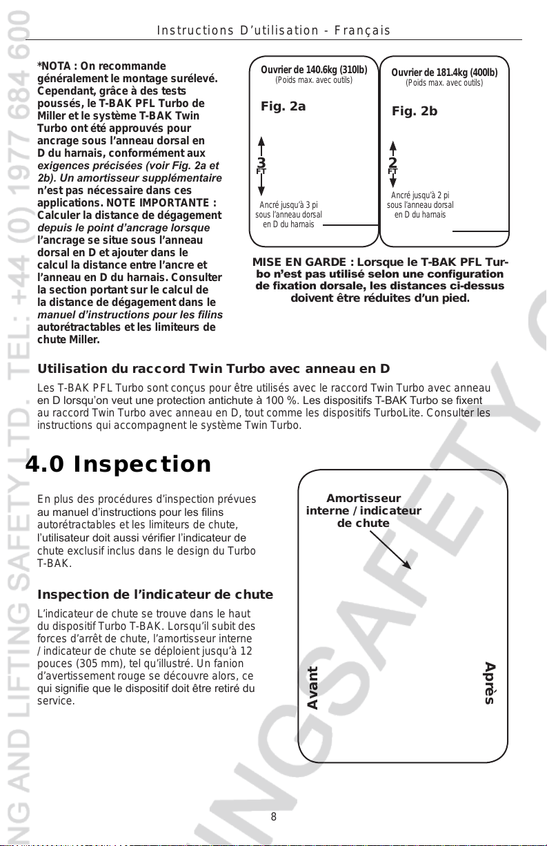
Singular gancho de
resorte 5K
Tejido especial para trabajo
pesado resistente a la abrasión
NOTA: Para asegurarse de que
la unidad Turbo está diseñada
para autoenganche de manera
segura, siempre verique
la etiqueta del producto, la
presencia del gancho de resorte
5K y el fácilmente identicable
tejido negro especial con listas
grises a lo largo del borde.
Los limitadores de caídas personales Miller Turbo T-BAK de autoenganche tienen un diseño
especial con tejido para trabajo pesado resistente a la abrasión y el gancho de resorte 5K,
el cual puede soportar 22.2 kN (5,000 lb) de fuerza en el linguete en cualquier ángulo, para
permitir conectarlo con la cuerda salvavidas de tejido a manera de lazada. NO intente este
tipo de conexión con limitadores de caídas personales TurboLite estándar u otras cuerdas
salvavidas autorretráctiles que no estén fabricados para soportar tal conexión.
¡No prestar atención a esta advertencia podría
causar lesiones graves o mortales!
3.0 Conexión e Instalación
Forma de efectuar
la conexión al
arnés
Una el cuerpo del
limitador de caídas
personal a la argolla “D”
posterior del arnés de
cuerpo entero mediante
el conector jado a la
unidad (p. ej., mosquetón, gancho de resorte, etc.)
u otro conector aprobado por Miller.
Forma de efectuar la instalación en
el anclaje
Escoja un lugar de instalación aprobado* que
cumpla todos los requisitos correspondientes a
anclajes, como una viga “I”.
Pase la cuerda salvavidas alrededor del anclaje y
conecte el gancho de resorte 5K a dicha cuerda a
manera de lazada. Asegúrese de que la cuerda
salvavidas quede capturada en el gancho de resorte
y el linguete de éste no quede obstruido de ninguna
manera. Verique que el gancho de resorte esté
completamente cerrado y asegurado.
Con la unidad Miller Turbo T-BAK, el
tamaño del anclaje compatible está
limitado únicamente por la longitud de
la cuerda salvavidas, por lo cual dicho
limitador es una de las más versátiles
unidades autorretráctiles de autoen-
ganche en el mercado hoy en día.
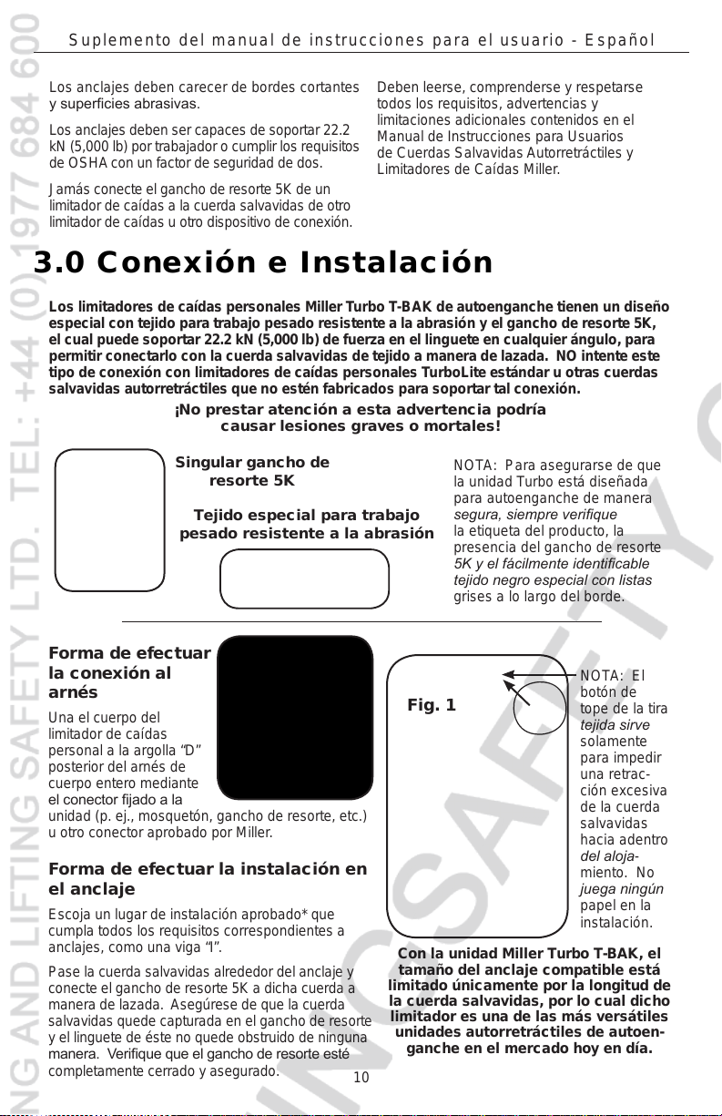
NOTA: El
botón de
tope de la tira
tejida sirve
solamente
para impedir
una retrac-
ción excesiva
de la cuerda
salvavidas
hacia adentro
del aloja-
miento. No
juega ningún
papel en la
instalación.
Fig. 1
Los anclajes deben carecer de bordes cortantes
y supercies abrasivas.
Los anclajes deben ser capaces de soportar 22.2
kN (5,000 lb) por trabajador o cumplir los requisitos
de OSHAcon un factor de seguridad de dos.
Jamás conecte el gancho de resorte 5K de un
limitador de caídas a la cuerda salvavidas de otro
limitador de caídas u otro dispositivo de conexión.
Deben leerse, comprenderse y respetarse
todos los requisitos, advertencias y
limitaciones adicionales contenidos en el
Manual de Instrucciones para Usuarios
de Cuerdas SalvavidasAutorretráctiles y
Limitadores de Caídas Miller.