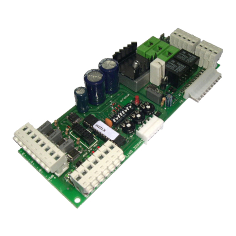
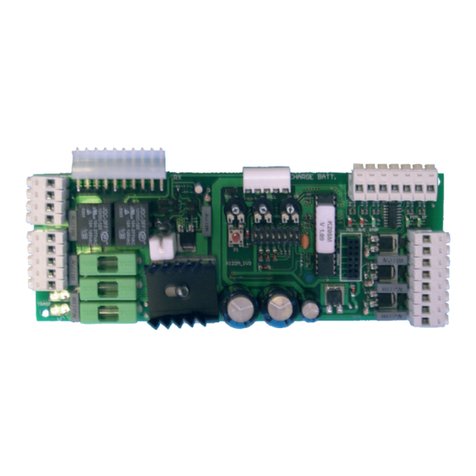
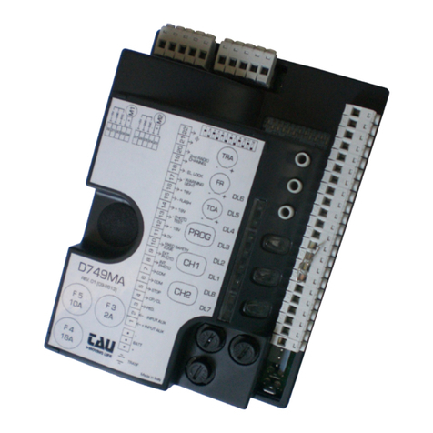
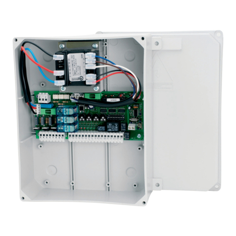
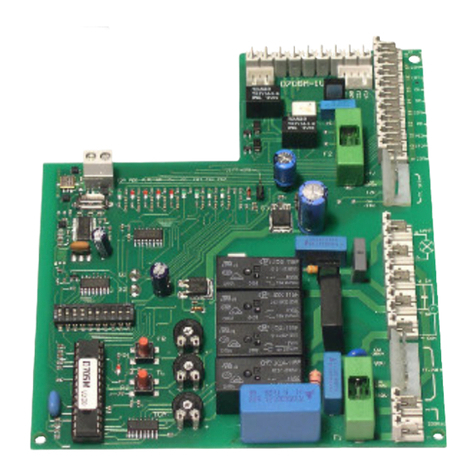
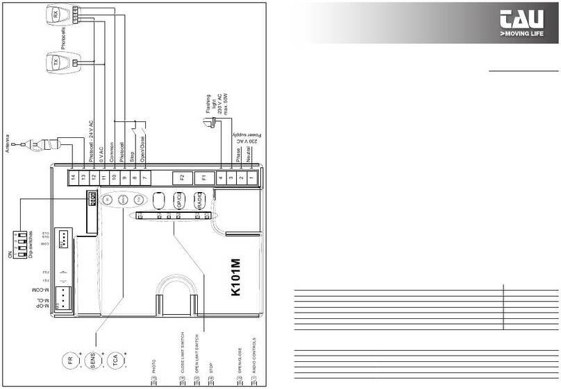
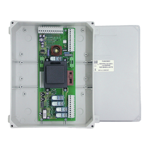
tau D705M User manual

1
D705M
GUIDA ALL’INSTALLAZIONE
INSTALLATION GUIDE
INSTALLATIONSANLEITUNG
NOTICE D’INSTALLATION
GUÍA PARA LA INSTALACIÓN
D705M
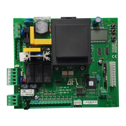
Quadro di comando per motoriuttore MASTER20Q
Control panel for MASTER20Q gearmotor
Steuerplatine für den getriebemotor MASTER20Q
Logique de commande pour motoréducteur MASTER20Q
Panel de mandos para motorreductor MASTER20Q
Via Enrico Fermi, 43 - 36066 Sandrigo (VI) Italia
Tel +39 0444 750190 - Fax +39 0444 750376
info@tauitalia.com - www.tauitalia.com
IT - Istruzioni originali
D-MNL0D705M 28-12-2011 - Rev.05

2
D705M
+
+
STOP PED P.P. CH CF FCC FCA FOT
TF.PRIM
TF. SEC
F1
D705M-1V0
F2
GND
ENC
+5V
GND
GND
FCC
FCA
24V
12V
80V
0V
(230V)
230V
1 2 4 5 6 7 8
M2
M3 M4
9 11 12 13 14 15 16 17 18
19 20 21 22 24 25 26 27
28 29
23
10
0V
(24V)
0V
(80V)
0V
(12V)
TCA
TL
+
-
-
-
FR
AP
P2
P1
G2
G1
G3
J1
U1A
C4
VR2
VR1
U11
U10
U9
U8
U5
U4
U2
U1
T2
T1
PR1
K6
K4
K3
K2
K1
F2
F1
C43
C38
C13
C5
C3
C45
K5
DL1
DL9
DL10
DL8
DL7
DL6
DL5
DL4
DL3
DL2
M1
230Vac
Power supply
Flashing
light
230Vac
max. 20W
Cap
12,5µF
Common
Phase
Neutral
Close
0 Vac
230 Vac
Common
Fixed safety edge
Common
Photocell
Photocell TX
Photocell RX - 24 Vac
0 Vac
0 Vac
Close
Open
Common
O/C
Ped
Stop
Open
Photocells
RX
1 2 3 4 5
TX
1 2
Gate open
warning light
max. 3W
Antenna
2nd radio
channel
+
+
STOP PED P.P. CH CF FCC FCA FOT
TF.PRIM
TF. SEC
F1
D705M-1V0
F2
GND
ENC
+5V
GND
GND
FCC
FCA
24V
12V
80V
0V
(230V)
230V
1 2 4 5 6 7 8
M2
M3 M4
9 11 12 13 14 15 16 17 18
19 20 21 22 24 25 26 27
28 29
23
10
0V
(24V)
0V
(80V)
0V
(12V)
TCA
TL
+
-
-
-
FR
AP
P2
P1
G2
G1
G3
J1
U1A
C4
VR2
VR1
U11
U10
U9
U8
U5
U4
U2
U1
T2
T1
PR1
K6
K4
K3
K2
K1
F2
F1
C43
C38
C13
C5
C3
C45
K5
DL1
DL9
DL10
DL8
DL7
DL6
DL5
DL4
DL3
DL2
M1
230Vac
Power supply
Flashing
light
230Vac
max. 20W
Cap
12,5µF
Common
Phase
Neutral
Close
0 Vac
230 Vac
Common
Fixed safety edge
Common
Photocell
Photocell TX
Photocell RX - 24 Vac
0 Vac
0 Vac
Close
Open
Common
O/C
Ped
Stop
Open
Photocells
RX
1 2 3 4 5
TX
1 2
Gate open
warning light
max. 3W
Antenna
2nd radio
channel

3
D705M
+
+
STOP PED P.P. CH CF FCC FCA FOT
TF.PRIM
TF. SEC
F1
D705M-1V0
F2
GND
ENC
+5V
GND
GND
FCC
FCA
24V
12V
80V
0V
(230V)
230V
1 2 4 5 6 7 8
M2
M3 M4
9 11 12 13 14 15 16 17 18
19 20 21 22 24 25 26 27
28 29
23
10
0V
(24V)
0V
(80V)
0V
(12V)
TCA
TL
+
-
-
-
FR
AP
P2
P1
G2
G1
G3
J1
U1A
C4
VR2
VR1
U11
U10
U9
U8
U5
U4
U2
U1
T2
T1
PR1
K6
K4
K3
K2
K1
F2
F1
C43
C38
C13
C5
C3
C45
K5
DL1
DL9
DL10
DL8
DL7
DL6
DL5
DL4
DL3
DL2
M1
230Vac
Power supply
Flashing
light
230Vac
max. 20W
Cap
12,5µF
Common
Phase
Neutral
Close
0 Vac
230 Vac
Common
Fixed safety edge
Common
Photocell
Photocell TX
Photocell RX - 24 Vac
0 Vac
0 Vac
Close
Open
Common
O/C
Ped
Stop
Open
Photocells
RX
1 2 3 4 5
TX
1 2
Gate open
warning light
max. 3W
Antenna
2nd radio
channel

4
D705M
DICHIARAZIONE DI INCORPORAZIONE DEL COSTRUTTORE
(ai sensi della Direttiva Europea 2006/42/CE AlI. II.B)
Fabbricante: TAU S.r.l.
Indirizzo: Via E. Fermi, 43
36066 Sandrigo (Vi)
ITALIA
Dichiara sotto la propria responsabilità che il prodotto: Centrale di comando
realizzato per il movimento automatico di: Cancelli Scorrevoli
per uso in ambiente: Condominiale / Industriale
completo di: Radioricevente
Modello: D705M
Tipo: D705M
Numero di serie: vedi etichetta argentata
Denominazione commerciale: Quadro di comando per motoriduttore
MASTER20Q
È realizzato per essere incorporato su una chiusura (cancello scorrevole) o per essere assemblato con altri dispositivi
al ne di movimentare una tale chiusura per costituire una macchine ai sensi della Direttiva Macchine 2006/42/CE.
Dichiara inoltre che questo prodotto è conforme ai requisiti essenziali di sicurezza delle seguenti ulteriori direttive
CEE:
- 2006/95/CE Direttiva Bassa Tensione
- 2004/108/CE Direttiva Compatibilità Elettromagnetica
ed, ove richiesto, alla Direttiva:
- 1999/5/CE Apparecchiature Radio e apparecchiature terminali di telecomunicazione
Dichiara inoltre che non è consentito mettere in servizio il macchinario no a che la macchina in cui sarà
incorporato o di cui diverrà componente sia stata identicata e ne sia stata dichiarata la conformità alle condizioni
della Direttiva 2006/42/CE.
Si impegna a trasmettere, su richiesta adeguatamente motivata delle autorità nazionali, informazioni pertinenti sulle
quasi-macchine.
Sandrigo, 31/03/2010
Il Rappresentante Legale
_________________________________________
Bruno Danieli
Nome e indirizzo della persona autorizzata a costituire la documentazione tecnica pertinente:
Loris Virgilio Danieli - via E. Fermi, 43 - 36066 Sandrigo (Vi) Italia
ITALIANO

5
D705M
AVVERTENZE
Il presente manuale è destinato solamente al personale tecnico qualicato per l’installazione.
Nessuna informazione contenuta nel presente fascicolo può essere considerata d’interesse per
l’utilizzatore nale. Questo manuale è allegato alla centralina D705M montata sul motoriduttore
MASTER20Q, non deve pertanto essere utilizzato per prodotti diversi!
Avvertenze importanti:
Togliere l’alimentazione di rete alla scheda prima di accedervi.
La centralina D705M è destinata al comando di un motoriduttore elettromeccanico per l’automa-
zione di cancelli, porte e portoni.
Ogni altro uso è improprio e, quindi, vietato dalle normative vigenti.
È nostro dovere ricordare che l’automazione che state per eseguire, è classicata come “co-
struzione di una macchina” e quindi ricade nel campo di applicazione della direttiva europea
2006/42/CE (Direttiva Macchine).
Questa, nei punti essenziali, prevede che:
- l’installazione deve essere eseguita solo da personale qualicato ed esperto;
- chi esegue l’installazione dovrà preventivamente eseguire “l’analisi dei rischi” della macchi-
na;
- l’installazione dovrà essere fatta a “regola d’arte”, applicando cioè le norme;
- inne dovrà essere rilasciata al proprietario della macchina la”dichiarazione di conformità”.
Risulta chiaro quindi che l’installazione ed eventuali interventi di manutenzione devono essere
effettuati solo da personale professionalmente qualicato, in conformità a quanto previsto dalle
leggi, norme o direttive vigenti.
Nella progettazione delle proprie apparecchiture, TAU rispetta le normative applicabili al prodot-
to (vedere la dichiarazione di conformità allegata); è fondamentale che anche l’installatore, nel
realizzare gli impianti, prosegua nel rispetto scrupoloso delle norme.
Personale non qualicato o non a conoscenza delle normative applicabili alla categoria dei “can-
celli e porte automatiche” deve assolutamente astenersi dall’eseguire installazioni ed impianti.
Chi non rispetta le normative è responsabile dei danni che l’impianto potrà causare!
Si consiglia di leggere attentamente tutte le istruzioni prima di procedere con l’installazione.
Installazione
L’installazione dovrà essere fatta a regola d’arte da personale qualicato. La Casa Costruttrice
declina ogni responsabilità per danni provocati da imperizia o inosservanza.
In particolare ricordiamo di:
1. scegliere la sezione dei cavi di potenza (alimentazione, motori, massa e lampeggiante) di
almeno 1.5 mm² e comunque in ragione degli assorbimenti e della lunghezza dei conduttori.
Ciò detto vale per la rimanenza dei cavi usati da dispositivi di comando e ausiliari con la sola
differenza della sezione minima che è ridotta a 0.5 mm²;
2. collegarsi alla morsettiera in modo da non alterare il grado di protezione offerto dal conte-
nitore, che deve essere posto in luogo asciutto e protetto;
3. tenere separati i cavi di potenza dai cavi dei circuiti ausiliari e di comando, specialmente per
percorsi lunghi;
4. cortocircuitare i contatti Normalmente Chiusi che non si dovessero utilizzare.
Si ricorda l’obbligo di mettere a massa l’impianto nonché di rispettare le normative
sulla sicurezza in vigore in ciascun paese.
ITALIANO

6
D705M
SCHEDA COMANDO PER MOTORE MONOFASE 230V AC
• LOGICA CON MICROPROCESSORE
• STATO DEGLI INGRESSI VISUALIZZATO DA LEDs
• PROTEZIONE INGRESSO LINEA CON FUSIBILE
• CIRCUITO DI LAMPEGGIO INCORPORATO
• FUNZIONE “UOMO PRESENTE”
• FRENATURA ELETTRICA
• INGRESSO PER TIMER SETTIMANALE
•
CONTROLLO DELLA COPPIA MOTORE E RILEVAMENTO OSTACOLI TRAMITE ENCODER
• RADIO RICEVITORE 433,92 MHz INTEGRATO A 2 CANALI (CH)
• CONTROLLO DEL BORDO SENSIBILE DI SICUREZZA
ATTENZIONE:
- non utilizzare cavi unilari (a conduttore unico), es. quelli citofonici, al ne di evi-
tare interruzioni sulla linea e falsi contatti.
- non riutilizzare vecchi cavi preesistenti.
COLLAUDO
A collegamento ultimato:
• I Leds verdi LS devono essere tutti accesi (corrispondono ciascuno ad un ingresso Normal-
mente Chiuso).
• Si spengono solo quando sono attivi i comandi ai quali sono associati.
• I Leds rossi LS devono essere tutti spenti (corrispondono ciascuno ad un ingresso Normal-
mente Aperto) si accendono solo quando sono attivi i comandi ai quali sono associati.
CARATTERISTICHE TECNICHE
Alimentazione scheda 230V AC - 50÷60Hz
Potenza nominale. 600 W ca.
Fusibile rapido protezione linea (F1 - 5x20) F3,15A - 250V AC
Tensione circuiti alimentazione motore 230V AC
Tensione alimentazione circuiti dispositivi ausiliari 24V AC
Fusibile rapido protezione linea 24 V ac (F2 - 5x20) F1,6A - 250V AC
Tensioni alimentazioni circuiti logici 5V DC
Temperatura di funzionamento -20°C ÷ + 55 °C
Grado di protezione del contenitore IP43
LED DI DIAGNOSI
DL1 (STOP) led verde di segnalazione pulsante STOP
DL2 (PEDESTRIAN) led rosso di segnalazione pulsante PEDONALE
DL3 (STEP BY STEP) led rosso di segnalazione pulsante PASSO-PASSO
DL4 (OPEN) led rosso di segnalazione pulsante APRE
DL5 (CLOSE) led rosso di segnalazione pulsante CHIUDE
DL6 (SENSITIVE EDGE) led verde di segnalazione BORDO SENSIBILE
DL7 (PHOTOCELL) led verde di segnalazione FOTOCELLULA
DL8 (CLOSE LIMIT SWITCH) led verde di segnalazione FINECORSA IN CHIUSURA
DL9 (OPEN LIMIT SWITCH) led verde di segnalazione FINECORSA IN APERTURA
DL10 (RADIO CONTROLS) led rosso di segnalazione
PROGRAMMAZIONE RADIOCOMANDI
ITALIANO

7
D705M
COLLEGAMENTI ALLA MORSETTIERA
Morsetti Funzione Descrizione
1 - 2 ALIMENTAZIONE (Power supply) ingresso ALIMENTAZIONE 230V AC
50÷60 Hz monofase;
M1 TRASFORMATORE connettore primario trasformatore [2 li bianchi (230V) + 2 li
rossi (80V)];
M2 TRASFORMATORE connettore secondario trasformatore [2 li neri (24V) + 2 li
blu (12V)];
4 - 5 - 6 MOTORE
(Motor) uscita MOTORE monofase 230 V ac, 600 W, comu-
ne=4, fase apertura=5, fase chiusura=6, collegare il conden-
satore tra i morsetti 5 e 6;
7 - 8 LAMPEGGIANTE
(Flashing light) uscita LAMPEGGIANTE 230 V ac, 20 W
max. Il segnale fornito è già opportunamente modulato per
l’uso diretto. La frequenza di lampeggio è doppia in fase di
chiusura; 7= 230 Vac, 8= 0 V
9 - 10 STOP
(Stop) ingresso pulsante STOP (contatto normalmente chiu-
so); il suo intervento provoca l’arresto dell’automazione. Al
successivo comando l’automazione esegue una manovra
opposta alla precedente (comune= 9);
9 - 11 PEDONALE
(Pedestrian) ingresso pulsante PEDONALE (contatto nor-
malmente aperto); consente l’apertura parziale (1 mt. ca.)
dell’automazione per consentire il passaggio pedonale (co-
mune= 9);
9 - 12 APRE/CHIUDE
(Open/Close) ingresso pulsante APRE/CHIUDE (contatto
normalmente aperto); per le modalità d’uso vedi le funzioni
dei dip-switches 2 - 4 e 10 (comune= 9);
13 - 14 APRE
(Open) ingresso pulsante APRE (contatto normalmente
aperto); per le modalità d’uso vedi le funzioni dei dip-switches
2 e 10 (comune= 13);
13 - 15 CHIUDE
(Close) ingresso pulsante CHIUDE (contatto normalmente
aperto); per le modalità d’uso vedi le funzioni dei dip-switches
2 e 10 (comune= 13);
13 - 16 FOTOCELLULE
(Photocell) ingresso FOTOCELLULE O DISPOSITIVI DI
SICUREZZA attivi in chiusura (contatto Normalmente Chiu-
so); il loro intervento, in fase di chiusura provoca l’arresto
seguito dalla totale riapertura del cancello, in fase di apertura
provoca la fermata temporanea del cancello no a rimozione
dell’ostacolo rilevato (solo se programmato dip switch nr. 3 in
ON), (13= Comune). Nel caso di più dispositivi di sicurezza,
collegare tutti i contatti NC IN SERIE.
17 - 18 BORDO
SENSIBILE
(Fixed safety edge) ingresso BORDO SENSIBILE (Bordo
sensibile resistivo o costa ssa);
Funziona solo durante la fase di apertura e provoca la fer-
mata temporanea del cancello e una parziale richiusura dello
stesso per circa 20 cm. liberando così l’eventuale ostacolo
(17= Comune).
Nota: se si collega un bordo sensibile resistivo cortocir-
cuitare il ponticelo J1;
Se si collega una costa ssa con contatto NC lasciare il
ponticello J1 aperto;
19 - 20 non connessi;
ITALIANO

8
D705M
21 - 22 2° CH RADIO
(2nd radio channel) uscita 2° CANALE RADIO (il suo fun-
zionamente dipende dai dip-switch nr 7 - 8) da utilizzarsi per
aprire/chiudere un altro cancello o per comandare le luci del
giardino, o per la funzione “ILLUMINAZIONE DI ZONA”;
Nota: per il collegamento di altri dispositivi al 2° canale
radio, quali accensione luci, comando pompe o carichi
importanti, utilizzare un relè ausiliario di potenza con
portata adeguata ai dispositivi da collegare, altrimenti
si potrebbero avere malfunzionamenti dovuti a disturbi
indotti.
23 - 24 TX FOTOCELLULE
(Photocell TX) uscita 24 Vac 10 W per l’ALIMENTAZIONE
DEL TX DELLE FOTO-CELLULE (solo quello che effettua il
Fototest) max. nr. 1 trasmettitore fotocellule.
23= 24 Vac, 24= 0 V;
Nota: il trasmettittore della fotocellula deve sempre
essere alimentato dai morsetti nr 23 - 24, in quanto su di
esso si effettua la verica del sistema di sicurezza (Foto-
test). Per eliminare la verica del sistema di sicurezza, o
quando non si usano le fotocellule, porre il dip-switch nr
6 in OFF. Se il fototest non va a buon ne, la centralina
non funziona;
25 - 26 FOTOCELLULE
(Photocell RX - 24 Vac) uscita 24 Vac 10 W per l’ALIMEN-
TAZIONE DELLE RX ED EVENTUALI ALTRI TX DELLE FO-
TOCELLULE, RICEVITORI ESTERNI, etc; collegare max. n°
3 coppie di fotocellule. 25= 0 V, 26= 24 Vac;
25 - 27 SPIA CANCELLO
APERTO
(Gate open warning light) uscita per SPIA CANCELLO
APERTO 24 Vac - max. 3 W; durante l’apertura del cancello
la spia lampeggia lentamente, a cancello aperto resta accesa
e durante la chiusura lampeggia a velocità doppia. Si spegne
al raggiungimento del FINE CORSA CHIUSURA (CLS). 25=
0 V, 27= 24 Vac;
28 - 29 ANTENNA (Antenna) ingresso ANTENNA (massa=28, segnale=29);
M3 FCC - FCA
(FCC) ingresso FINE CORSA CHIUSURA
(contatto normalmente chiuso);
(FCA) ingresso FINE CORSA APERTURA
(contatto normalmente chiuso);
ingresso MICRO DI SICUREZZA (contatto normalmente
chiuso), alla rimozione del carter il motore si arresta.
ATTENZIONE: la scheda resta in tensione!
M4 ENCODER innesto rapido per connessione ENCODER.
Blu= 0 Vcc (GND), marrone= 5 Vcc (+5V), bianco= SEGNA-
LE ENCODER (ENC);
REGOLAZIONI LOGICHE
TRIMMER
T.L. regolazione Tempo di Lavoro: da 5 a 240 secondi ca.;
T.C.A.
regolazione Tempo di Chiusura Automatica: da 5 a 120 secondi ca. (vedi dip-
switch nr. 1);
FR. regolazione sensibilità rilevamento ostacoli (solo per motori provvisti di En-
coder).
Nota: ruotando i TRIMMER in senso orario si aumentano le regolazioni, vicever-
sa, ruotandoli in senso antiorario, diminuiscono.
ITALIANO

9
D705M
Dip switch
1 On ad apertura completata, la chiusura del cancello è automatica trascorso un tempo
impostato sul trimmer T.C.A.;
Off la chiusura necessita di un comando manuale;
2 On ad automazione funzionante, una sequenza di comandi di apertura/chiusura induce il
cancello ad una APERTURA-CHIUSURA-APERTURA-CHIUSURA, etc. (vedi anche
dip switch 4);
Off nelle stesse condizioni, la stessa sequenza di comandi di apertura/chiusura induce
il cancello ad una APERTURA-STOP-CHIUSURA-STOP-APERTURA-STOP, etc.
(funzione passo-passo);
3 On durante la fase di apertura la fotocellula interviene arrestando il cancello no a rimo-
zione dell’ostacolo rilevato. Alla rimozione dell’ostacolo il cancello riprende l’apertura;
Off durante la fase di apertura la fotocellula non interviene;
4 On funzione NO-REVERSE attiva; il cancello ignora i comandi di chiusura durante l’aper-
tura e l’inversione di marcia avviene solo in fase di chiusura;
Off azionando il pulsante apre-chiude avremo una inversione di marcia anche in fase
di apertura;
5 On ENCODER inserito: funzione rilevamento ostacoli tramite encoder attiva (agire sul
trimmer FR per regolare la sensibilità sull’ostacolo);
Off ENCODER escluso;
6 On la funzione prelampeggio e “verica delle fotocellule” è inserita;
Off la funzione prelampeggio e “verica delle fotocellule” è disinserita; N.B.: da utilizzare
quando non si usano le fotocellule;
7 - 8 funzionamento 2° CANALE RADIO (morsetti nr 18 - 19);
Dip 7 Dip 8 Funzione
Off Off
Contatto cancello aperto: il contatto si attiva all’apertura del cancello, rima-
ne attivo durante il tempo di apertura, durante il TCA e durante la richiusura.
Si disattiva una volta che il cancello ha completato la chiusura.
Off On Funzione bistabile attiva: all’ impulso del radiocomado il contatto si attiva e
rimane tale no al successivo impulso.
On Off Funzione monostabile attiva 2 sec.: all’ impulso del radiocomado il contatto
si attiva e rimane tale per 2 sec.
On On Funzione monostabile attiva 180 sec.: all’ impulso del radiocomado il con-
tatto si attiva e rimane tale per 180 sec.
9 On attiva frenata;
Off escludi frenata;
Nota: il sistema di frenata si aziona ogni qualvolta il motore deve fermasi (CLS - OLS -
STOP - inversione di marcia) e attenua l’inerzia accumulata dal cancello durante la corsa.
10 On Uomo Presente; l’automazione continuerà ad aprire o a chiudere no a quando si
manterrà premuto il pulsante APRI o il pulsante CHIUDI. Al rilascio dello stesso si
otterrà l’arresto del motoriduttore;
Off normale (o impulsivo); ad un comando sul pulsante APRI, CHIUDI o PP, l’automazione
effettuerà un’apertura o una chiusura completa;
Nota: in modalità Uomo Presente l’ingresso PP (n° 12) viene escluso, così come la radio
ricevente.
J1 ponticellato: bordo sensibile resistivo;
non ponticellato: costa ssa con contatto NC.
ITALIANO

10
D705M
FUNZIONI AVANZATE
Funzione orologio: è possibile utilizzare un timer (esempio settimanale) collegato all’ingresso
del pulsante apre-chiude o ingresso passo-passo per mantenere aperto il cancello in determi-
nate fascie orarie e permetterne poi la richiusura automatica.
Il cancello rimane aperto nchè l’ingresso Ap/Ch o passo-passo rimane impegnato.
Funzione “contatto cancello aperto”: ponendo il dip 7 ed il dip 8 in OFF, il 2° ch radio (mor-
setti nr 18 - 19) funzionerà da contatto pulito che indica quando il cancello è aperto. È possibile
utilizzare questa funzione per collegare una “ILLUMINAZIONE DI ZONA” o come segnalazione
di cancello aperto.
Funzione “Pedonale con 2° ch radio”: chiudendo i contatti delle gocce G1 e G2 e ponendo dip
7 (ON) e dip 8 (OFF), si può utilizzare il 2° ch radio per effettuare l’apertura pedonale.
RADIO RICEVITORE 433,92 MHz INTEGRATO
Il radio ricevitore può apprendere no ad un max di 30 codici a dip-switches (TXD2, TXD4, BUG2,
BUG4, K-SLIM, K-SLIM-C, T-4, T-4C) o rolling code (BUG2R, BUG4R, K-SLIM-RP, T-4RP) da
impostare liberamente su due canali.
Il primo canale comanda direttamente la scheda di comando per l’apertura dell’automazione; il
secondo canale comanda un relè per un contatto pulito N.A. in uscita (morsetti 21 - 22, max 24
Vac, 1 A).
La modalità di apprendimento (dip-switches o rolling code) viene determinata dal primo radio-
comando e rimarrà la stessa no alla cancellazione totale di tutti i codici di entrambi i canali.
APPRENDIMENTO RADIOCOMANDI
P1 = APRE/CHIUDE
P2 = 2° canale
1_ premere brevemente il tasto P1 se si desidera associare un radiocomando alla funzione
APRE/CHIUDE;
2_ il led DL10 si spegne per indicare la modalità di apprendimento dei codici (se non viene im-
messo nessun codice entro 10 secondi, la scheda esce dalla modalità di programmazione);
3_ premere il tasto del radiocomando che si desidera utilizzare;
4_ il led DL10 si riaccende per segnalare l’avvenuta memorizzazione (se ciò non accade, atten-
dere 10 secondi e riprendere dal punto 1);
5_ se si desidera memorizzare altri radiocomandi, ripetere la procedura dal punto 1 no ad un
massimo di 30 trasmettitori;
6_ se si desidera effettuare la memorizzazione sul 2° canale, ripetere la procedura dal punto 1
utilizzando il tasto P2 anzichè il tasto P1;
7_ se si desidera uscire dalla modalità di apprendimento senza memorizzare un codice, premere
brevemente il tasto P1 o il tasto P2.
Nel caso di raggiungimento del nr massimo di radiocomandi (nr 30), il led DL10
inizierà a lampeggiare velocemente per circa 3 secondi senza però eseguire la
memorizzazione.
PROGRAMMAZIONE REMOTA TRAMITE T-4RP, K-SLIM-RP e BUG-R
Con la versione di software V 2.xx è possibile eseguire l’apprendimento remoto con i radioco-
mandi T-4RP, K-SLIM-RP e BUG-R, ossia senza agire direttamente sui tasti di programmazione
della ricevente.
Sarà sufciente disporre di un radiocomando già programmato nella ricevente per poter aprire la
procedura di programmazione remota dei nuovi radiocomandi, programmati tramite TAUPROG.
Seguire la procedura riportata sulle istruzioni del radiocomando T-4RP, K-SLIM-RP e BUG-R.
ITALIANO

11
D705M
CANCELLAZIONE RADIOCOMANDI
1_ tenere premuto per 3 secondi ca. il tasto P1 al ne di cancellare tutti i radiocomandi ad esso
associati;
2_ il led DL10 inizia a lampeggiare lentamente per indicare che la modalità di cancellazione è
attivata;
3_ tenere premuto nuovamente il tasto P1 per 3 secondi;
4_ il led DL10 si spegne per 3 secondi ca. per poi riaccendersi sso ad indicare l’avvenuta can-
cellazione;
5_ riprendere la procedura dal punto 1 utilizzando il tasto P2 per cancellare tutti i radiocomandi
ad esso associati;
6_ se si desidera uscire dalla modalità di cancellazione senza memorizzare un codice, premere
brevemente il tasto P1 o il tasto P2.
ATTENZIONE: Se si desidera memorizzare un nuovo tipo di telecomando (es: da
dip-switches a rolling code o viceversa) è necessario cancellare entrambi i canali.
MALFUNZIONAMENTI: POSSIBILI CAUSE E RIMEDI
1_ L’automazione non parte
a_ Vericare con lo strumento (Multimetro) la presenza dell’alimentazione 230Vac;
b_ Vericare che i contatti N.C. della scheda siano effettivamente normalmente chiusi (5 led
verdi accesi);
c_ Vericare che il led rosso DL10 sia acceso sso;
d_ Impostare il dip 3 (funzione uomo presente) su OFF, il dip 5 (encoder) su OFF, il dip 6
(fototest) su OFF;
e_ Controllare con lo strumento (Multimetro) che i fusibili siano integri.
2_ Il radiocomando ha poca portata
a_ Controllare che il collegamento della massa e del segnale dell’antenna non sia invertito;
b_ Non eseguire giunzioni per allungare il cavo dell’antenna;
c_ Non installare l’antenna in posizioni basse o in posizioni nascoste dalla muratura o dal
pilastro;
d_ Controllare lo stato delle pile del radiocomando.
3_ Il cancello si apre al contrario
a_ Invertire (tra di loro) i cablaggi delle fasi del motore (morsetti 5 - 6) e quelli dei necorsa
(li rosso e arancione).
ITALIANO

12
D705M
MANUFACTURER’S DECLARATION OF INCORPORATION
(in accordance with European Directive 2006/42/EC App. II.B)
Manufacturer: TAU S.r.l.
Address: Via E. Fermi, 43
36066 Sandrigo (Vi)
ITALY
Declares under its sole responsibility, that the product: Electronic control unit
designed for automatic movement of: Sliding Gates
for use in a: Communities / Industrial
complete with: Radioreceiver
Model: D705M
Type: D705M
Serial number: see silver label
Commercial name: Control panel for MASTER20Q gearmotor
Has been produced for incorporation on an access point (sliding gate) of for assembly with other devices used
to move such an access point, to constitute a machine in accordance with the Machinery Directive 2006/42/EC.
Also declares that this product complies with the essential safety requirements of the following EEC directives:
- 2006/95/EC Low Voltage Directive
- 2004/108/EC Electromagnetic Compatibility Directive
and, where required, with the Directive:
- 1999/5/CE Radio equipment and telecommunications terminal equipment
Also declares that it is not permitted to start up the machine until the machine in which it is incorporated or of
which it will be a component has been identied with the relative declaration of conformity with the provisions of
Directive 2006/42/EC.
The manufacturer undertakes to provide, on sufciently motivated request by national authorities, all information
pertinent to the quasi-machinery.
Sandrigo, 31/03/2010
Legal Representative
_________________________________________
Bruno Danieli
Name and address of person authorised to draw up all pertinent technical documentation:
Loris Virgilio Danieli - via E. Fermi, 43 - 36066 Sandrigo (Vi) Italy
ENGLISH

13
D705M
WARNINGS
This manual has been especially written for use by qualied tters. No information given in this
manual can be considered as being of interest to end users. This manual is attached to the
D705M control unit mounted on the MASTER20Q gearmotor, therefore it may not be used for
different products!
Important information:
Disconnect the panel from the power supply before opening it.
The D705M control unit has been designed to control an electromechanical gear motor for au-
tomating gates and doors of all kinds.
Any other use is considered improper and is consequently forbidden by current laws.
Please note that the automation system you are going to install is classi ed as “machine con-
struction” and therefore is included in the application of European directive 2006/42/EC (Ma-
chinery Directive).
This directive includes the following prescriptions:
- Only trained and qualied personnel should install the equipment;
- the installer must rst make a “risk analysis” of the machine;
- the equipment must be installed in a correct and workmanlike manner in compliance with all
the standards concerned;
- after installation, the machine owner must be given the “declaration of conformity”.
This product may only be installed and serviced by qualied personnel in compliance with cur-
rent, laws, regulations and directives.
When designing its products, TAU observes all applicable standards (please see the attached
declaration of conformity) but it is of paramount importance that installers strictly observe the
same standards when installing the system.
Unqualied personnel or those who are unaware of the standards applicable to the “automatic
gates and doors” category may not install systems under any circumstances.
Whoever ignores such standards shall be held responsible for any damage caused by
the system!
Do not install the unit before you have read all the instructions.
Installation
This product must be correctly installed by a qualied tter. The maker declines all liability for
damage caused by incapacity or neglect.
In particular:
1. make sure the cross-section of the power cables (power input, motors, earth and ashing
light) is at least 1.5 mm² and, in any case, sufcient for the absorption and length of the
wires. The above also applies to the other cables used by control and auxiliary devices ex-
cept that the minimum cross-section is reduced to 0.5 mm²;
2. make connections to the terminal board so as not to alter the level of protection offered by
the container which must be installed in a dry and protected place;
3. keep the power circuits separate from the control and auxiliary circuits, especially if the ca-
bles are long;
4. short any unused Normally Closed contacts.
The product must be properly earthed and the safety regulations in force in the
country of installation must be observed.
ENGLISH

14
D705M
CONTROL PANEL FOR 230 Vac SINGLE-PHASE MOTOR
• MICROPROCESSOR-CONTROLLED LOGIC
• INPUT STATUS LED’S
• LINE INPUT FUSE
• BUILT-IN FLASHING LIGHT CIRCUIT
• “MAN PRESENT” FUNCTION
• ELECTRIC BRAKING
• WEEKLY TIMER INPUT
• MOTOR TORQUE CONTROL AND OBSTACLE DETECTION BY MEANS OF ENCODER
• 433.92 MHz 2 CHANNEL BUILT-IN RADIO RECEIVER (CH)
• CONTROL OF THE SENSITIVE EDGE
ATTENTION:
- do not use single cables (with one single wire), ex. telephone cables, in order to
avoid breakdowns of the line and false contacts.
- do not re-use old pre-existing cables.
TESTING
When all connections have been made:
• All the green LS LED’s must be on (each corresponds to a Normally Closed input).
• They only turn off when the commands they are associated with are active.
• All the red LS LED’s must be off (each corresponds to a Normally Open input) they only turn
on when the commands they are associated with are active.
TECHNICAL CHARACTERISTICS
Power input to board 230V AC - 50÷60Hz
Nominal power 600 W ca.
Primary input line rapid fuse (F1 - 5x20) F3,15A - 250V AC
Input voltage of motor circuits 230V AC
Input voltage of auxiliary circuits 24V AC
24Vac line rapid fuse (F2 - 5x20) F1,6A - 250V AC
Logic circuit input voltage 5V DC
Working temperature -20°C ÷ + 55 °C
Box protected to IP43
DIAGNOSTICS LED
DL1 (STOP) STOP button green LED signal
DL2 (PEDESTRIAN) PEDESTRIAN button red LED signal
DL3 (STEP BY STEP) STEP BY STEP button red LED signal
DL4 (OPEN) OPEN button red LED signal
DL5 (CLOSE) CLOSE button red LED signal
DL6 (SENSITIVE EDGE) SENSITIVE EDGE green LED signal
DL7 (PHOTOCELL) PHOTOCELL green LED signal
DL8 (CLOSE LIMIT SWITCH) CLOSE LIMIT SWITCH green LED signal
DL9 (OPEN LIMIT SWITCH) OPEN LIMIT SWITCH green LED signal
DL10 (RADIO CONTROLS) RADIO CONTROLS programming red led
ENGLISH

15
D705M
TERMINAL BOARD CONNECTIONS
Terminals Function Description
1 - 2 POWER SUPPLY (Power supply) POWER input 230Vac, 50Hz, single-phase;
M1 TRANSFORMER transformer primary connector [2 white wires (230V) + 2 red
wires (80V)];
M2 TRANSFORMER transformer secondary connector [(2 black wires (24V) + 2
blue wires (15V)];
4 - 5 - 6 MOTOR (Motor) MOTOR output single-phase 230Vac, 600 W, com-
mon=4, opening phase=5, closing phase=6, connect the ca-
pacitor between terminals 5 and 6;
7 - 8 FLASHING LIGHT (Flashing light) FLASHING LIGHT output 230 Vac 50 W
max. The signal is already modulated for direct use. Flashing
frequency during closing is double. 7= 230 Vac, 8= 0 V
9 - 10 STOP (Stop) STOP button input (normally closed contact); this
stops the automatic system. At the next command, the oppo-
site operation to the previous one is performed (common=9);
9 - 11 PEDESTRIAN (Pedestrian) PEDESTRIAN button input (normally open con-
tact); partially opens the automatic system (by about 1 m) to
allow pedestrians to pass by (common=9);
9 - 12 OPEN/CLOSE (Open/Close) OPEN/CLOSE button input (contact normally
open); for operating information see dip switch 2 - 4 and 10
functions (common=9);
13 - 14 OPEN (Open) OPEN button input (contact normally open); for op-
erating information see dip switch 2 and 10 functions (com-
mon=13);
13 - 15 CLOSE (Close) CLOSE button input (contact normally open); for op-
erating information see dip switch 2 and 10 functions (com-
mon=13);
13 - 16 PHOTOCELL
(Photocell) input for PHOTOCELLS OR SAFETY DEVICES
active during closure (Normally Closed contact); They stop
the gate during closing and totally reopen it; they temporarily
stop the gate during opening in order to allow the obstacle
to be removed (if dip switch n° 3 set to ON), (13= Common).
If there is more than one safety device, connect all the NC
contacts IN SERIES.
17 - 18 FIXED SAFETY
EDGE
(Fixed safety edge) SENSITIVE EDGE input (resistive sen-
sitive edge or xed safety edge);
Works only when the gate is opening; temporarily stops the
gate and partially closes it by about 20 cm in order to allow
the obstacle to be removed. (17=Common);
Note: if a resistive sensitive edge is connected, short
jumper J1;
If a xed edge with NC contact is connected, leave jump-
er J1 open;
19 - 20 not connected;
21 - 22 2nd RADIO CH
(2nd radio channel) 2nd RADIO CHANNEL output (its op-
eration depends on dip-switches nos. 7 - 8) to be used for
opening/closing another gate, for controlling garden lights or
for the “ZONE LIGHTING” function;
Warning: to connect other devices to the 2nd Radio
Channel (area lighting, pumps, etc.), use an additional
auxiliary relay.
ENGLISH

16
D705M
23 - 24 PHOTOCELL TX
(Photocell TX) 24 Vac 10 W POWER output for PHOTO-
CELL TX (only the one that performs the Phototest) max. no.
1 photocell transmitter. 23= 24 Vac, 15= 24 Vac;
Note: the photocell transmitter must always be supplied
by terminals no. 23 - 24, since the safety system test
(phototest) is carried out on it. To override the testing of
the safety system, or when the photocells are not used,
set dip-switch no. 6 to OFF. If the phototest is not suc-
cessful, the control unit will not operate;
25 - 26 PHOTOCELL
(Photocell RX - 24 Vac) 24 Vac 10 W output to POWER THE
RXs AND ANY OTHER TXs OF PHOTOCELLS THAT ARE
PRESENT, EXTERNAL RECEIVERS, etc.; connect a max.
of 3 pair of photocells. 25= 0 V, 26= 24 Vac;
25 - 27 GATE OPEN
WARNING LIGHT
(Gate open warning light) GATE OPEN WARNING LIGHT
output 24 Vac - max. 3 W; during opening of the gate the
warning light ashes slowly, when the gate is open it remains
steadily illuminated and during closure it ashes twice as
fast. Turns off when the CLOSING LIMIT SWITCH (CLS) is
reached. 25= 0 V, 27= 24 Vac;
28 - 29 ANTENNA (Antenna) ANTENNA input (earth=28, signal=29);
M3 FCC - FCA
(FCC) CLOSE LIMIT SWITCH input (normally closed contact);
(FCA) OPEN LIMIT SWITCH input (normally closed contact);
SAFETY MICROSWITCH input (normally closed contact),
the motor stops when the guard is removed. WARNING: the
control unit is still live!
M4 ENCODER
quick coupling for ENCODER connection.
Blue= 0 Vdc (GND), brown= 5 Vdc (+5V), white= ENCODER
SIGNAL (ENC);
LOGIC ADJUSTMENTS
TRIMMER
T.L. Work Time adjustment: from approx. 5 to 240 seconds;
T.C.A.
Automatic Closing Time adjustment: from approx. 5 to 120 seconds (see dip
switch 1);
FR. obstacle detection sensitivity adjustment.
Note: turn the TRIMMER clockwise to increase adjustments; turn it anticlock-
wise to decrease.
Dip switch
1 On after opening, the gate automatically closes when the delay set on the T.C.A. trim-
mer expires;
Off a command is required to close the gate;
2 On with automatic closing enabled, a sequence of open/close commands causes the
gate to OPENCLOSE-OPEN-CLOSE etc (see also dip switch 4).
Off in the same conditions, the same command sequence causes the gate to OPEN-
STOP-CLOSESTOP-OPEN-STOP (step-by-step).
ENGLISH

17
D705M
3 On during opening, the photocell cuts in to stop the gate until the obstacle is removed.
When the obstacle is removed the gate resumes opening;
Off during opening, the photocell does not cut in.
4 On NO-REVERSE function activated; the gate ignores the closure commands during
opening and reversal of movement occurs only during closure;
Off the open-close pushbutton reverses the direction of movement of the gate even while
it is opening.
5 On ENCODER enabled: encoder obstacle detection function activated (use the trimmer
FR to adjust the sensitivity to obstacles);
Off ENCODER disabled;
6 On pre-ashing and “photocell test” function enabled;
Off pre-ashing and “photocell test” function disabled; N.B.: to be used when the pho-
tocells are not used.
7 - 8 2nd RADIO CHANNEL operation (terminals no. 18 - 19)
Dip 7 Dip 8 Function
Off Off
Gate contact open: The contact activates on opening the gate and remains
active during the open time, during the TCA and during reclosure. It deacti-
vates once the gate has completed its closure movement.
Off On Bistable function active: the radio control impulse causes the contact to
activate and remain active until the subsequent impulse.
On Off Monostable function active for 2 sec.: the radio control impulse causes the
contact to activate and remain active for 2 sec.
On On Monostable function active for 180 sec.: the radio control impulse causes
the contact to activate and remain active for 180 sec.
9 On braking enabled;
Off braking disabled;
Note: the braking system activates whenever the motor must stop (CLS - OLS - STOP
– change of direction) and reduces the inertia accumulated by the gear motor during
movement.
10 On
Man Present; the automation system will continue to open or close as long as the
OPEN or CLOSE buttons are held down. The gear motor will stop when the button
is released;
Off normal (or pulse); when the OPEN, CLOSE or the PP button is pushed, the automatic
system performs a complete opening or closing manoeuvre;
Note: in the Man Present mode, the PP input (n° 12) is disabled, as is the radio receiver.
J1 jumper inserted: resistive sensitive edge;
jumper not inserted: xed edge with NC contact.
ADVANCED FUNCTIONS
Clock function: a timer can be connected to the open-close pushbutton in order to keep the
gate open at certain times during the day, after which it reverts to automatic closing.
The gate remains open as long as the Op/Cl input continues to be activated.
“Gate open contact” function: when dipswitch 7 and dipswitch 8 are set to OFF, the second
radio channel (terminals no. 18 - 19) will act as a voltage-free contact to indicate when the gate
is open. This function can be used to connect “ZONE LIGHTING” or as a gate open indicator.
ENGLISH

18
D705M
“Pedestrian with 2nd radio ch.” function: when drop contacts G1 and G2 are closed and
when dipswitch 7 is ON and 8 is OFF, the second radio channel can be used to make the pe-
destrian opening.
433.92 MHz BUILT-IN RADIO RECEIVER
The radio receiver can learn up to a maximum of 30 dip-switches (TXD2, TXD4, BUG2, BUG4,
K-SLIM, K-SLIM-C, T-4, T-4C) or rolling codes (BUG2R, BUG4R, K-SLIM-RP, T-4RP) which can
be set on the two channels as required.
The rst channel directly commands the control board for opening the automatic device; the
second channel commands a relay for a N.O. no-voltage output contact (terminals 18 and 19,
max. 24 Vac, 1 A).
The learning mode (dip-switch or rolling code) is determined by the rst radio control device and
remains unchanged until all the codes have been cancelled.
LEARNING SYSTEM FOR RADIO CONTROL DEVICES
P1 = OPEN/CLOSE
P2 = 2nd channel
1_ press button P1 briey to associate a radio control device with the OPEN/CLOSE function;
2_ LED DL8 turns off to indicate that the code learning mode has been activated (if no code is
entered within 10 seconds, the board exits the programming mode);
3_ press the button of the relative radio control device;
4_ LED DL8 turns on again to indicate that the code has been memorised (if this does not hap-
pen, wait 10 seconds and start again from point 1);
5_ to memorise codes to other radio control devices, repeat the procedure from point 1 up to a
maximum of 30 transmitters;
6_ to memorise codes on the 2nd channel, repeat the procedure from point 1 using button P2
instead of P1;
7_ to exit the learning mode without memorising a code, press button P1 or P2 briey.
If the maximum number of radio controls is reached (30), the LED DL8 will begin to
ash rapidly for about 3 seconds but without performing memorisation.
REMOTE PROGRAMMING BY MEANS OF T-4RP, K-SLIM-RP and BUG-R
With the new version of software V 2.xx it is possible to carry out the remote self-learning of
the new version of transmitters T-4RP, K-SLIM-RP and BUG-R, that is without pressing the re-
ceiver’s programming buttons.
It will be sufcient to have an already programmed transmitter in the receiver in order to start
the procedure of remote programming of the new transmitters, programmed by means of TAU-
PROG. Follow the procedure written on the instructions of the transmitter T-4RP, K-SLIM-RP
and BUG-R.
CANCELLING CODES FROM RADIO CONTROL DEVICES
1_ keep button P1 pressed for 3 seconds in order to cancel all the associated radio control
devices;
2_ LED DL8 ashes slowly to indicate that the cancellation mode has been activated;
3_ press button P1 again for 3 seconds;
4_ LED DL8 turns off for approx. 3 seconds and then remains steady to indicate that the code
has been cancelled;
5_ repeat the procedure from point 1 using button P2 to cancel all the associated radio control
devices;
6_ to exit the learning mode without memorising a code, press button P1 or P2 briey.
ATTENTION: TO memorise a code on a new type of remote control unit (e.g.: from
dip-switch to rolling code or vice-versa) both channels must be cancelled.
ENGLISH

19
D705M
MALFUNCTIONS: POSSIBLE CAUSES AND SOLUTION
1_ The automation does not start
a_ Check there is 230Vac power supply with the multimeter;
b_ Check that the NC contacts of the card are actually normally closed (5 green LEDs on);
c_ Check that the red LED DL10 is steadily illuminated;
d_ Set the dip 3 (man present function) to OFF, dip 5 (encoder) to ON, dip 6 (phototest) to
OFF;
e_ Check that the fuses are intact with the multimeter.
2_ The radio control has very little range
a_ Check that the ground and the aerial signal connections have not been inverted;
b_ Do not make joints to increase the length of the aerial wire;
c_ Do not install the aerial in a low position or behind walls or pillars;
d_ Check the state of the radio control batteries.
3_ The gate opens the wrong way
a_ Invert the motor phase wires (terminals 5 - 6) and also those of the limit switches (red and
orange wires).
ENGLISH

20
D705M
INTEGRIERUNGSERKLÄRUNG DES HERSTELLERS
(gemäß der Europäischen Richtlinie 2006/42/EG Anl. II.B)
Hersteller: TAU S.r.l.
Adresse: Via E. Fermi, 43
36066 Sandrigo (Vi)
ITALY
Erklärt unter seiner Haftung, dass das Produkt: Elektronische Steuerung
für die automatische Bewegung von: Schiebetore
für eine Anwendung: Gewerbe / Industrie
Einschließlich: Empfänger
Modell: D705M
Typ: D705M
Seriennummer: siehe Silberetikette
Handelsbezeichnung: Steuerplatine für den getriebemotor MAS-
TER20Q
ausgeführt wurde, um in einen Verschluss integriert zu werden (Schiebetore) oder um mit anderen Vorrichtungen
kombiniert zu werden, um diesen Verschluss zu bewegen, und somit gemäß der Maschinenrichtlinie 2006/42/EG
eine Maschine darstellt.
Außerdem erklärt er, dass dieses Produkt den grundsätzlichen Sicherheitseigenschaften der folgenden Richtlini-
en EWG entspricht:
- 2006/95/EG Niederspannungsrichtlinie
- 2004/108/EG Richtlinie für elektromagnetische Kompatibilität
Und wo gefordert, der Richtlinie:
- 1999/5/CE Radio equipment and telecommunications terminal equipment
Außerdem wird erklärt, dass es nicht zugelassen ist, die Vorrichtung in Betrieb zu setzen, bis die Maschine, in
die sie integriert wird oder deren Bestandteil sie sein wird, identiziert und die Konformität gegenüber dem Inhalt
der Richtlinie 2006/42/EG erklärt wurde.
Er verpichtet sich, auf ausdrücklichen Wunsch der nationalen Behörden, Informationen über die Fastmaschinen
zu übersenden.
Sandrigo, 31/03/2010
Der gesetzliche Vertreter
_________________________________________
Bruno Danieli
Name und Adresse der beauftragten Person zur Vorlegung der zugehörigen technischen Unterlagen:
Loris Virgilio Danieli - via E. Fermi, 43 - 36066 Sandrigo (Vi) Italy
DEUTSCH
Other manuals for D705M
2
Table of contents
Languages:
Other tau Control Panel manuals
Popular Control Panel manuals by other brands

Chipkin
Chipkin Mircom PRO2000 FS-8705-17 instruction manual
Texecom
Texecom Veritas 8 installation manual

Bavaria Yachts
Bavaria Yachts 301 instruction manual

Plymovent
Plymovent CONTROLPRO instructions
Siemens
Siemens Multi Panel MP270 SIMATIC HMI Equipment manual
AFL Hyperscale
AFL Hyperscale U Series installation guide
