16
K120M
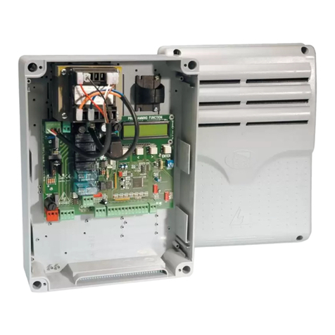
CONNECTIONS TO TERMINAL BOARD
Terminals Function Description
FS1 - FS2 POWER
SUPPLY
board supply input 18,5 V AC – Powered by the toroidal trans-
former housed in the T-ONE3B motor and protected by a fuse
on the 230 V AC power supply.
1 - 3 FIXED SAFETY
EDGE
SENSITIVE EDGE input (resistive sensitive edge or xed safety
edge); Works only when the gate is opening; temporarily stops
the gate and partially closes it by about 20 cm in order to allow
the obstacle to be removed.
1= SENSITIVE EDGE, 3= COMMON.
Note: if a resistive sensitive edge is connected, set dip-
switch no. 9 to ON;
If a xed safety edge with NC contact is connected, set dip-
switch no. 9 to OFF.
2 - 3 PHOTOCELLS
input for PHOTOCELLS OR SAFETY DEVICES active during
closure (Normally Closed contact); They stop the gate during
closing and totally reopen it; they temporarily stop the gate dur-
ing opening in order to allow the obstacle to be removed (if dip
switch n° 3 set to ON). If there is more than one safety device,
connect all the NC contacts in series. 2= PHOTOCELL.
Note: the photocell transmitter must always be supplied
by terminals no. 10 - 11, since the safety system test (pho-
totest) is carried out on it. To override the testing of the
safety system, or when the photocells are not used, set dip-
switch no. 6 to OFF. If the phototest is not successful, the
control unit will not operate.
4 - 5 STOP
STOP pushbutton input (Normally Closed contact); It stops the
gate in any position, temporarily inhibiting its automatic closing,
if programmed. 4= COMMON, 5= STOP.
4 - 6 OPEN/CLOSE
OPEN/CLOSE pushbutton input (Normally Open contact); It
commands the opening and closing of the gate and its operation
is controlled by dip-switches 2 and 4. 5= OPEN/CLOSE.
4 - 7 PEDESTRIAN
PEDESTRIAN pushbutton input (Normally Open contact); It
commands the partial opening and closing of the gate for ~1 m
of travel and its operation is controlled by dip-switches 2 and 4.
7= PEDESTRIAN.
8 - 9 PHOTOCELLS
24 V DC, max. 15 W, output to POWER THE RXs AND ANY
OTHER TXs OF PHOTOCELLS THAT ARE PRESENT, EX-
TERNAL RECEIVERS, etc.; connect a max. of 3 pair of photo-
cells. 8= NEGATIVE, 9= POSITIVE.
10 - 11 PHOTOCELL
TX
24 V DC, output for PHOTOCELL TX (only the one that per-
forms the Phototest) max. no. 1 photocell transmitter.
10= NEGATIVE, 11= POSITIVE.
12 - 13 FLASHING
LIGHT
FLASHING LIGHT output 24 V DC, max. 20 W. The signal is al-
ready modulated for direct use. Flashing frequency during clos-
ing is double. 12= NEGATIVE, 13= POSITIVE.
14 - 15 GATE OPEN
WARNING LIGHT
GATE OPEN LED output 24 V DC, max. 3 W; during opening of
the gate the warning light ashes slowly, when the gate is open
it remains steadily illuminated and during closure it ashes twice
as fast. 14= NEGATIVE, 15= POSITIVE.
ENGLISH


