manuals.online logo
Brands
  1. Home
  2. •
  3. Brands
  4. •
  5. Teknion
  6. •
  7. Indoor Furnishing
  8. •
  9. Teknion hiSpace User manual

Teknion hiSpace User manual

height-adjustable bench - hiSpace
INDEX
By Section
Product Name
Product
Code
Guide
No.
Last
Updated
Product Name
Product
Code
Guide
No.
Last
Updated
Product Name
Product
Code
Guide
No.
Last
Updated
INSTALLATION SUPPORT DOCUMENTS
Typical Installation Sequence Sep 2018
FRAMES AND WORKSURFACE
hiSpace Universal Frame HBBFYS 111
May 2020
hiSpace Rectangular Worksurface HBBWRL
Frame Grommet Cap HHBFGC
SCREENS AND GABLES
hiSpace - Center Casual Screen - Solid HHBCCS 211a May 2017
hiSpace Center Casual Screen - Fabric HHBCCF 211b May 2017
hiSpace - Desk Edge Screen - Solid HHBCDS 212a May 2017
hiSpace - Desk Edge Screen - Fabric HHBCDF 212b May 2017
hiSpace - Desk Edge Screen - Glass HHBCDG 212c May 2017
ELECTRICS
Power Harness HHBEPH 311a May 2017
Power Box HHBEPB
Chicago Power Box HHBEPBCH
Extension Harness HHBEEH
hiSpace Base Feed HHBEBF 311b May 2017
hiSpace Split Base Feed HHBEBFS
hiSpace Chicago Base Feed HHBEBFCH
hiSpace Cable Riser HHBECR
E-Chain - hiSpace HHBEEC 311c May 2017
hiSpace Under Worksurface Cover HHBWUC 311d Aug 2017
hiSpace Cable Tray Cover HHBFCC
hiSpace Ceiling Feed HHBECF 312 May 2017
hiSpace Chicago Ceiling Feed HHBECFCH
hiSpace Power Pole HHBEPP
*Click on the desired Installation Guide to jump to the Guide
page.
May 2020
PAGE 1 OF 1
P1A
hiSpace Universal Frame (HHBFYS), hiSpace Rectangular Worksurface (HHBWRL)
& Frame Grommet Cap (HHBFGC)
A
DB
C
Section:
Description: Page No:
Date:
Rev. No: 5
FRAME & WORKSURFACES ASSEMBLY
FRAMES & WORKSURFACES
May 2020 1 of 11
HABH_111
Installation Guides
height-adjustable bench
D12
Part and Product Identification
Hispace Frame Reconfiguration Kit, Mid
(HHBFRK2) xQty varies
D
D
B
Hispace Frame Reconfiguration Kit, End
(HHBFRK1) x1
Hispace Frame Reconfiguration Kit End Split
(HHBFRK3) x 1
C
B
Part and Product Identification
A1 - Hispace Rectangular
Worksurface
(C05-9246-X)x1
C1 -Gable Frame Sub Assy
(N09-5359)x2 & Front
Covers (A16-3590)x4
Section:
Description: Page No:
Date:
Rev. No: 5
FRAME & WORKSURFACES ASSEMBLY
FRAMES & WORKSURFACES
May 2020 2 of 11
HABH_111
A - Hispace Rectangular Worksurface (HHBWRL)x4
A2 - Rectangular Grommet
(RAGC7)xQty Varies
A3 - Center Electrical Grommet Kit - 3
Outlet & 1 VDM Style Data Opening -
Jacks not included
(CEG1-YEPS301) xQty varies
A4 - Center Electrical Grommet Kit - 3
Outlet & 2 USB Charging Ports
(CEG2-XEPB320) xQty varies
B- End Gable Hispace (N09-5336)x2
B1 -End Gable Out Cover
(A16-3592)x1
B2 -Gable Inner Cover
Sub Assy
(N09-5401)x1
(Comes Assembled)
C- Mid Gable Hispace (N09-5337)xQty varies
C2 -Mid Gable
Top Cover
(A16-3599) x2
C5 -Gable Inner
Cover SubAssy
(N09-5401) x2
D- Cable Tray Assembly (N09-5339)x2
Leg Kit (N09-5785) x2 Worksurface Hardware Kit (X05-0314)x1
D7 -1/4-20 UNC X0.5" 2A
Cross/Sq Comb Sock. Trs
Head Mach Scr Steel Zn
(E01-0110)x12
D8 -Based on Teknion Quebec
part E01-50702: M6 X 1 X
14mm (E01-0602)x8
D9 -#10X0.875" Lg. Screw
Quad Pan Washer
(E07-0077)x8
D1 -Cable Tray Hispace
(N09-5331-X)x1
D2 -Worksurface Channel
Assy Hispace
(N09-5814-X)x2
D3 -Worksurface Angle
(A16-4187L/R)x2
each
D4 -Leg Assenbky
(D06-4132)x2
D5 - Key Pad
(D06-4276) x1
D6 -Control Box with
Anti-collision 100-240
VAC
(D06-4275/650) x1
D10 -#4X0.75" Wood Screw
F.H. Quad Zn
(E04-0081)x6
D11 -M6X16mm Hex Socket
Button Hd Screw Zn
(E01-0967)x16
Installation Guides
height-adjustable bench
A5 - Wood Screw (FS8-5/8PB)x4
D12 - Grommet Cover
(HHBFGC)x1
(Comes Assembled)
(Comes Assembled) (Comes Assembled)
B4 -Gable Frame
Top Plate Sub
Assembly
(N09-5358) x1
C6 -Gable Hex
Head Screw
(E01-0965) x8
B5 -Gable Hex
Head Screw
(E01-0965)x4
B3 -1/4-20 UNC X0.5" 2A
Cross/Sq Comb Sock. Trs
Head Mach Scr Steel Zn
(E01-0110)x8
C3 -1/4-20 UNC X0.5" 2A Cross
/Sq Comb Sock.Trs Head
Mach Scr Steel Zn
(E01-0110)x16
C4 -Gable Frame Top Plate
Sub Assembly
(N09-5358) x2
D13 - Right-Angle Connector
Cable, 1m Lg, Hispace Table
(D06-4277) xvaries
D14 - 3M US/Canada Power
Cord
(D06-4136) xvaries
STEP 2: Insert Frame Top Plate into End Gable, Mid Vertical Tube. Make sure Top Plate &
Vertical Tube align. Secure Top Plate in place.
STEP 1: Pull Gable Inner Cover outward and lift it afterwards, to remove it from End Gable
Section:
Description: Page No:
Date:
REMOVE END GABLES INNER COVER INSTALL END GABLES TOP PLATE
HABH_111
3 of 11
May 2020
ASSEMBLE END GABLES
FRAMES & WORKSURFACES
NOTE: End Gables
are shipped assembled,
except for Top Plate.
B1
Mid Vertical
Tube
B4
B2
B3
B4
B1
Installation Guides
height-adjustable bench
STEP 3: Pull Gable Inner Cover outward and lift it afterwards, to remove it from End Gable.
Repeat, to remove the Inner Cover on the opposite side.
STEP 3: Pull Top Covers upward and remove them from Mid Gable Assembly.
STEP 4: Insert Frame Top Plate into End Gable, Mid Vertical Tube. Make sure Top Plate &
Vertical Tube align. Secure Top Plate in place. Repeat on the opposite side. If specified, Install
Power Module inside of Mid Gable - Refer to HAB_311a for procedure instructions.
Section:
Description: Page No:
Date:
REMOVE MID GABLE TOP COVERS
REMOVE MID GABLE INNER COVERS
INSTALL MID GABLE TOP PLATES
HABH_111
4 of 11
May 2020
ASSEMBLE MID GABLES - IF SPECIFIED
FRAMES & WORKSURFACES
NOTE: Mid Gable is
shipped assembled,
except for Top Plate.
IMPORTANT: If Mid
Gables are not specified,
skip steps 3 to 5 C2
C1
C5
C1
C4
C3
NOTE: For Power
Module installation
inside of Mid Gable
Refer to HAB_311a.
Installation Guides
height-adjustable bench
STEP 5: Loosen the set screws to move them out of the way to avoid scratching the surface of
legs. STEP 6: Insert Legs into Gables. Fasten each Leg in place, using the two M6x20mm Hex Head
Screws located at the bottom of the Gables.
Section:
Description: Page No:
Date:
LOOSEN THE SET SCREWS FROM GABLES INSERT & SECURE LEGS INTO GABLES
HABH_111
5 of 11
May 2020
ASSEMBLE END & MID GABLES
FRAMES & WORKSURFACES
D4
B
C
End Gables
Mid Gables
D4
Installation Guides
height-adjustable bench
B5
C6
NOTE: Before installing
legs, ensure the set screws
on the gables are removed
to prevent scratches.
B
C
End Gables
Mid Gables
Gable
Set Screw
Gable
Set Screw
D13
0.5
STEP 8: Adjust the levelers to bring the legs into the same horizontal plane determined with the self-leveling
laser leveler, before proceeding to the next step.
STEP 7: Place Gables in their Approximate location. Bring over Cable Tray and align round
hole with correspondent Gable Top Plate hole to determine Gable proper location. Fasten
screws into round holes first. Use one of the slot holes on each side of the Cable Tray, after.
Adjust levelers for all Legs to be 0.5" off the edge.
Section:
Description: Page No:
Date:
DETERMINE GABLES PROPER LOCATION ALIGN LEGS
HABH_111
6 of 11
May 2020
FRAME ASSEMBLY
FRAMES & WORKSURFACES
height-adjustable bench
Installation Guides
IMPORTANT: Please refer to HAB_311 for
installation of Electric Components into Cable
Tray & Mid Gable.
D1
BC
D7
D1
Use Cable Tray
round hole, as guide
to properly locate
Gables.
NOTE: Use laser mark tool to check alignment
NOTE: The unit must be levelled at the exact
location of use
Laser Line
STEP 10: Attach Worksurface Angles to Legs with screws provided, as shown. Make sure the
shorter side of the angle faces the user.
STEP 9: Place Worksurface Channels on top of Legs. Make sure the holes align and fasten as
shown, using four screws per leg.
Section:
Description: Page No:
Date:
INSTALL WORKSURFACE CHANNELS INSTALL WORKSURFACE ANGLES TO LEGS
HABH_111
7 of 11
May 2020
FRAME ASSEMBLY
FRAMES & WORKSURFACES
height-adjustable bench
Installation Guides
D2
D4 D11
D2
B
D3
NOTE: End Gable shown for demonstration
D8
D3
STEP 12: To put Gables Inner Cover back, bring it in an angle and make sure the slots at the
bottom of the cover engage in the bottom End/Mid Gable Assembly Lips. For Mid Gables
only, place Top Covers back as shown.
NOTE: Must raise the legs before installing Gable Covers.
STEP 11: Tighten Gables Set Screw to prevent Legs from moving inside of the Gables.
Section:
Description: Page No:
Date:
TIGHTEN GABLES SET SCREW REINSTALL COVERS BACK
HABH_111
8 of 11
May 2020
ASSEMBLE END & MID GABLES
FRAMES & WORKSURFACES
D4
B
C
End Gables
Mid Gables
D4
End Gables
Mid Gables
C2
Mid Gable
Assembly Lip
B2
End Gable
Assembly Lip
Installation Guides
height-adjustable bench
Legs & Cable Tray not
shown for better visibility
Legs & Cable Tray not
shown for better visibility
Gable
Set Screw
D12 C5
Install Grommet
Cap if E-Chain
is not specified.
NOTE: Remove the
covers if needed.
Gable
Set Screw
STEP 13: Place Control Box into Worksurface Channel and slide it onto Worksurface Channel
Support Plate. Connect Legs and Switch to Control Box.
Section:
Description: Page No:
Date:
INSTALL CONTROL BOX DETAIL
HABH_111
9 of 11
May 2020
FRAMES & WORKSURFACES
Underside View
Note: Gables & Cable
Tray not shown
D5
D2
Support Plate -
Worksurface
Channel
D6 D4
D6
To Switch
To Legs
Installation Guides
height-adjustable bench
Front
Back
Make sure to insert
through E-Chain
NOTE: Electrical Power
Plug should be installed
facing the location of the
power box.
D14
Section:
Description: Page No:
Date:
INSTALL WORKSURFACES
May 2020
10 of 11
HABH_111
FRAMES & WORKSURFACES
STEP 14: Bring Worksurfaces on top of Hispace Frame. Align Worksurface holes with Worksurface Angle holes, Worksurface Channel and Control Box. Fasten worksurfaces in place, as shown.
Underside View
Note: Gables, Cable Tray and
Control Box Cable
connections not shown
A1
D7
D9
D7
D9
Installation Guides
height-adjustable bench
STEP 16: When specified, insert Bottom part of Rectangular Grommet into Worksurface cut
out. Bring together Grommet Covers as shown, and insert them into Grommet Bottom part.
For Center Electrical Grommet Kits: Insert from the top, Grommet Cover into Worksurface
rectangular cutout. Fasten Electrical Outlets at the bottom of the Worksurface, as shown.
STEP 15: Align Swithches & Worksurfaces holes. Fasten Switches to Worksurface with screws
provided.
Section:
Description: Page No:
Date:
INSTALL SWITCHES INSTALL GROMMETS - IF SPECIFIED
HABH_111
11 of 11
May 2020
FRAMES & WORKSURFACES
Underside View
Underside View
D10
A4
A1
D10
A4
A2
A2
A4
A1
A1
A2
Installation Guides
height-adjustable bench
A5
A5
hiSpace - Center Casual Screen - Solid (HHBCCS) Part and Product Identification
A - Wood Fixed HT Screen
(C0S-9308) x1
For Customer Support please contact
[email protected]
Section:
Description: Page No:
Date:
Rev. No: 01
May 2017 1 of 3
HABH_211a
height-adjustable bench
B1 - Wood Screen Mounting Bracket
(A16-3622) x4
B2 - 1/4-20 UNC x 0.500" 2A, Cross/
SQ. COMB. Socket, TRS. Head,
Machine Screw, Steel, ZN
(E01-0110) x4
B3 - Murakoshi Screw, 1/4-20x15mm
(JCBB), Zinc
(E01-0635) x8
B4 - Joint Connector Nuts;
1/4-20x17mm; (JN96035)
(E03-0482) x8
B - Mounting Kit Wood Fixed HT Screen (X02-0108) x1
A
B
STEP 2: Fasten Mounting Brackets onto Cable Tray loosely.STEP 1: Secure Mounting Brackets to Casual Screen with Murakoshi Screws and Joint Nuts.
Section:
Description: Page No:
Date:
INSTALL MOUNTING BRACKETS ATTACH SCREEN
HABH_211a
2 of 3
May 2017
height-adjustable bench
A
B4
B3
B1
B2
STEP 3: Ensure Casual Screen is located at the center of the bench, then tighten Screws to secure it in place.
height-adjustable bench
Section:
Description: Page No:
Date:
ADJUST & SECURE SCREEN
May 2017 3 of 3
HABH_211a
C
L
hiSpace Center Casual Screen - FABRIC (HHBCCF) Part and Product Identification
A - Center Casual Screen
(HHBCCF) x1
Fabric Screen shipped pre-assembled
For Customer Support please contact
[email protected]
Section:
Description: Page No:
Date:
Rev. No: 01
May 2017 1 of 4
HABH_211b
height-adjustable table
B1 - Support Bracket - Fabric Screen
(A16-3492) x2
B2 - #8x1-1/4 Type AB Flat Quadrex
Head Self Tapping Screw Steel ZP
(E01-0947) x6
B3 - 1/4-20 UNC x0.500"2A,
Cross/Square COMB. Socket, TRS
Head, Machine Screw, Steel, ZN
(E01-0110) x4
B - Mounting Kit for Fabric Screen(X03-0243) x1
A
B1
STEP 1: Secure Support Brackets to Fabric Screen.
height-adjustable table
B2
A
Section:
Description: Page No:
Date:
MOUNTING BRACKETS ASSEMBLY
May 2017 2 of 4
HABH_211b
B1
B2
STEP 2: Fasten Support Brackets onto Cable Tray with Screws. Make sure to keep Screws loose for adjustment.
height-adjustable table
B3
Section:
Description: Page No:
Date:
FASTEN SCREEN (LOOSELY)
May 2017 3 of 4
HABH_211b
Cable Tray
STEP 3: Ensure Fabric Screen is located at the center of the Cable Tray, then tighten Screws to secure it in place.
height-adjustable table
Section:
Description: Page No:
Date:
ADJUST & SECURE SCREEN
May 2017 4 of 4
HABH_211b
C
L
Top View
Detail View
hiSpace - Desk Edge Screen - Solid (HHBCDS) Part and Product Identification
For Customer Support please contact
[email protected]
Section:
Description: Page No:
Date:
Rev. No: 01
May 2017 1 of 3
HABH_212a
height-adjustable bench
A - Desk Edge Wood Screen -
Hispace (C05-9305) x1
B - Mounting Desk Edge Screen Mounting Kit(X06-0339) x1
B1 - Desk Edge Screen
Bar-Sub-Assembly
for Wood (N09-5045) x1
B2 - Desk Edge Screen
Mounting Bracket
(A16-2959) x1
B3 - Machine Screw,
1/4-20x1-1/8" Long,
Flat, Quadrex, Zinc
(E01-0906) 48"-54" x3
60"-66" x4
72"-96" x5
B4 - #10x1" Pan Quad. Wood
Screw Deep Thread Zn
(E07-0097)
48"x10 54"-60"x14
66"-72"x18 78"-84"x22
90"x26 96"x30
A
B1
B2
NOTE: If 48" & 54" Desk Edge Screen is
specified, Rectangular Grommet CAN NOT
be specified at center.
Desk Edge Screen (HHBCDS1354) shown as
an example.

Other manuals for hiSpace

3

Other Teknion Indoor Furnishing manuals
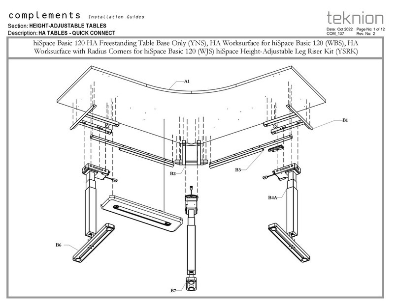
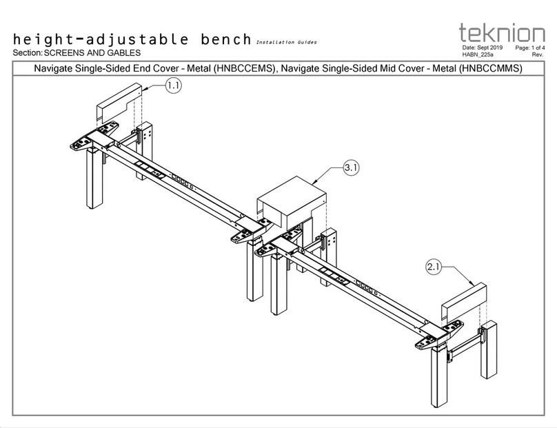
Teknion Navigate End Cover-Metal Operating and maintenance instructions

Teknion

Teknion Navigate End Cover-Metal Operating and maintenance instructions
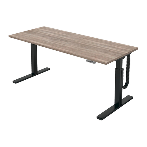
Teknion dossier ZJNL User manual

Teknion

Teknion dossier ZJNL User manual

Teknion HTSFT User manual

Teknion

Teknion HTSFT User manual

Teknion District Operating and maintenance instructions
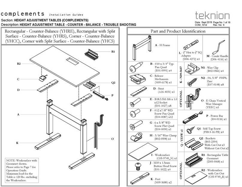
Teknion

Teknion District Operating and maintenance instructions
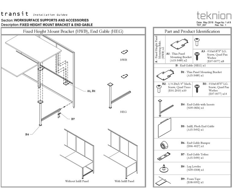
Teknion BGATHB User manual

Teknion

Teknion BGATHB User manual

Teknion Navigate Single-Sided Frame HNBFNZ User manual

Teknion

Teknion Navigate Single-Sided Frame HNBFNZ User manual

Teknion RKXD Operating and maintenance instructions
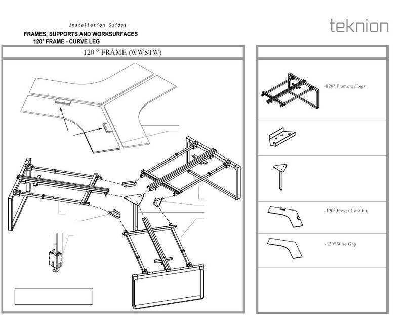
Teknion

Teknion RKXD Operating and maintenance instructions

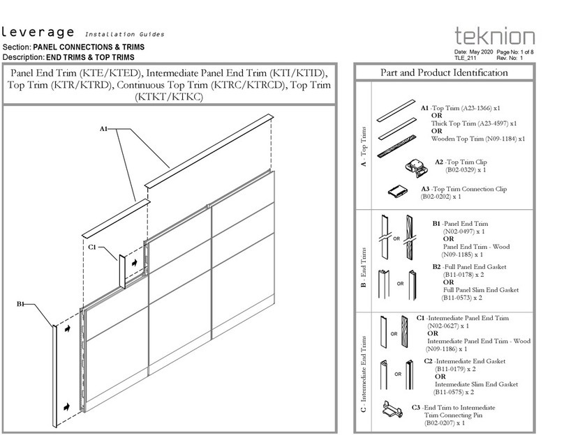
Teknion Leverage Operating and maintenance instructions

Teknion

Teknion Leverage Operating and maintenance instructions

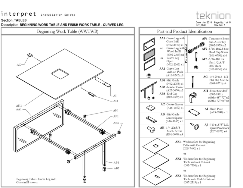
Teknion Beginning Work Table User manual

Teknion

Teknion Beginning Work Table User manual

Teknion mina User manual

Teknion

Teknion mina User manual

Teknion Interpret Operating and maintenance instructions

Teknion

Teknion Interpret Operating and maintenance instructions

Teknion UNSF User manual

Teknion

Teknion UNSF User manual

Teknion zones Operating and maintenance instructions

Teknion

Teknion zones Operating and maintenance instructions

Teknion ZNTLCS Operating and maintenance instructions

Teknion

Teknion ZNTLCS Operating and maintenance instructions

Teknion interpret WWCBSD Operating and maintenance instructions

Teknion

Teknion interpret WWCBSD Operating and maintenance instructions

Teknion Dossier ZJSF Operating and maintenance instructions

Teknion

Teknion Dossier ZJSF Operating and maintenance instructions

Teknion hiSpace Technical manual

Teknion

Teknion hiSpace Technical manual

Teknion HABCCMML Operating and maintenance instructions

Teknion

Teknion HABCCMML Operating and maintenance instructions

Teknion Interpret WWSSB Operating and maintenance instructions

Teknion

Teknion Interpret WWSSB Operating and maintenance instructions

Teknion Interpret Chicago WWEPMCH User manual

Teknion

Teknion Interpret Chicago WWEPMCH User manual

Teknion District Series User manual

Teknion

Teknion District Series User manual

Teknion hiSpace User manual

Teknion

Teknion hiSpace User manual

Teknion complements LIVELLO Operating and maintenance instructions
Teknion

Teknion complements LIVELLO Operating and maintenance instructions
Teknion HWBWBD User manual

Teknion

Teknion HWBWBD User manual

Popular Indoor Furnishing manuals by other brands
RIGHT ANGLE R-Style Tango Assembly instructions

RIGHT ANGLE

RIGHT ANGLE R-Style Tango Assembly instructions

Project Source W3030B Assembly instruction

Project Source

Project Source W3030B Assembly instruction

Frisco 322631 instruction manual

Frisco

Frisco 322631 instruction manual

Dorel Home Products 4024259 Assembly instructions

Dorel Home Products

Dorel Home Products 4024259 Assembly instructions

Otto 762308 Assembly instructions

Otto

Otto 762308 Assembly instructions

Manutti Flex instruction manual

Manutti

Manutti Flex instruction manual

Jysk JERSORE 910-216-1061 manual

Jysk

Jysk JERSORE 910-216-1061 manual

Contour Genie quick start guide

Contour

Contour Genie quick start guide

Munchkin brica Night Light Baby In-Sight owner's manual

Munchkin

Munchkin brica Night Light Baby In-Sight owner's manual

AZZURRA GABRIELLA H.180 Assembly instructions
AZZURRA

AZZURRA GABRIELLA H.180 Assembly instructions
needs&wants Tably1 + Tably2 quick start guide

needs&wants

needs&wants Tably1 + Tably2 quick start guide

Coaster 203503 Assembly instructions

Coaster

Coaster 203503 Assembly instructions

Practical Cabinets B09 Assembly instructions

Practical Cabinets

Practical Cabinets B09 Assembly instructions

Easy EASYindustry Wall installation manual

Easy

Easy EASYindustry Wall installation manual

Die Hausmarke 321 quick start guide

Die Hausmarke

Die Hausmarke 321 quick start guide

Jar Furniture KARLA Assembly instructions

Jar Furniture

Jar Furniture KARLA Assembly instructions

HECOL Moveis RK-2112 Assembly instructions

HECOL Moveis

HECOL Moveis RK-2112 Assembly instructions

Discovery Telecom 80255 manual

Discovery Telecom

Discovery Telecom 80255 manual

manuals.online logo
manuals.online logoBrands
  • About & Mission
  • Contact us
  • Privacy Policy
  • Terms and Conditions

Copyright 2025 Manuals.Online. All Rights Reserved.