manuals.online logo
Brands
  1. Home
  2. •
  3. Brands
  4. •
  5. Teknion
  6. •
  7. Indoor Furnishing
  8. •
  9. Teknion HWBWBT Operating and maintenance instructions

Teknion HWBWBT Operating and maintenance instructions

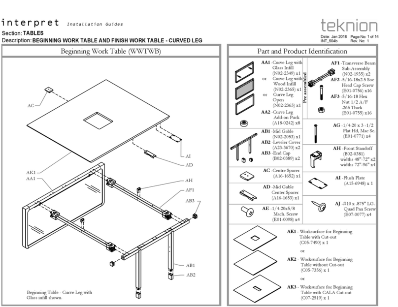
120 Worksurface w/ Square Corners (HWBWBT), 120 Worksurface w/ Radius Corners(HWBWJT), 120 Frame (HWBFYT),
Section:
Description: Page No:
Date:
Rev. No: 0
120 FRAME HAB
HEIGHT ADJUSTABLE BENCH
Sept 2022 1 of 29
HABH_120
height-adjustable bench
Installation Guides
A1 or A2
B1
C1 or C2
C12
D1
G1
G4
Part and Product Identification
Section:
Description: Page No:
Date:
Rev. No: 0
FRAME 120 HAB
HEIGHT ADJUSTABLE BENCH
Sept 2022 2 of 29
HABH_120
height-adjustable bench
Installation Guides
A1 - 120 Worksurface
w/ Square Corners
(HWBWBT) x 1
A- Worksurface
A2 - 120 Worksurface w/
Round Corners
(HWBWJT) x 1
OR
B- Worksurface Frame 120
(N01-7755) x 3
B1 - Leg Mount
Bracket
Weldment
(N09-9873) x 2
B3 -Hi-Space 3
PT Stiffner
(A16-11207X) x 2
B4 - #10
x 0.875" LG.
Screw,
(E07-0077)x85
120 Frame (HWBFYT)
C1-Leg L/R
(N01-4852)x6
C5 - Keypad,
hiSpace Table
(D06-4276) x3
C7 -Hi-Space
Motor Cable
(N09-9455/25)x3
(N09-9455/10)x6
C8 - Cable Clamp
(B02-0558) x30
C9 -5x25mm
Wood Screw
(E01-1415) x6
C11 -3.1x19mm
Wood Screw
(E01-1470) x10
C10 - Control Box
3 Leg BIFMA
(N09-9457) x3
C12 -3.5x15mm
Wood Screw
(E01-1417) x30
C13 -3m Power
Cord
(D06-4136) x3 C14 -Cam Handle
(N09-9814) x9
C3- Leg L/R
(N01-7476) x6
C6 -Toggle
Switch
(N01-7336) x3
120 Frame (HWBFYT)
D-Frame
Connecting Tube
Assy (N01-4877-X)
D1 -Frame
Connecting TubeAssm. DS
(N01-4877-X) x 3
D2 -M8x25mm
Flat SHS
(E01-1410) x12
E -Leveler, M6 x 54mm
Long
(D06-4291) x18
F -Worksurface
Alignment Bracket,
(A16-9660) x3
120 Frame (HWBFYT)
G4-Clamping Sleeve
Assy (N01-8288)x3
G-Frame Link Kit, 120/
Frame LinkKit, 120, Fix
Height(X01-4498)
/(X01-4703) x1
G1-Frame Link Assy
(N07-7481)x1
G2-Arm Cover Assy
(N01-8025)x3
G3-Clamping Plate
(A16-10918)x3
G5-MK-M6x1.0x16mm
(E01-1409)x12
G6-Clamping Plate for
FixedHeight
(A16-11069)x3
G7- Alignment Plate for
FixedHeight
(A16-11125)x1
B2 - Leg Mount
Bracket Short
(N01-4900) x 1
C2-Leg
(N09-9282)x3 C4 - Leg
(N01-7475) x3
Section:
Description: Page No:
Date:
PLACE AND ALIGN WORKSURFACES
Sept 2022 3 of 29
HABH_120
FRAME 120 HAB
HEIGHT ADJUSTABLE BENCH
height-adjustable bench
Installation Guides
STEP 1: Place all the 3 worksurfaces upside down on the ground with the pilot holes facing up and align with each other as shown
A1 or A2
NOTE: Worksurfaces upside down
Section:
Description: Page No:
Date:
ATTACH LEG MOUNT BRACKET WELDMENT ATTACH 3 PT STIFFNER
HABH_120
4 of 29
Sept 2022
FRAME 120 HAB
HEIGHT ADJUSTABLE BENCH
height-adjustable bench
Installation Guides
STEP 2: Attach the Leg Mount Bracket Weldment to Three Worksurfaces and secure with
provided screws.
NOTE: Have Shown only one
Worksurface, follow the same step
for remaining 2 worksurfaces
NOTE: Have Shown only one
Worksurface, follow the same step
for remaining 2 worksurfaces
NOTE: Do not over tighten NOTE: Do not over tighten
STEP 3: Attach the Hi-Space 3 PT Stiffner to the Worksurfaces and secure in place with
provided screws.
B1
B4
B4
B3
B4
B2
Section:
Description: Page No:
Date:
ATTACH LEGS TO BRACKET SECURE LEGS-C1
HABH_120
5 of 29
Sept 2022
FRAME 120 HAB
HEIGHT ADJUSTABLE BENCH
height-adjustable bench
Installation Guides
STEP 4A: Attach Legs to the Leg Mounts by lining up with holes. Brackets should face towards
the back of each Worksurface. STEP 5A: Push Legs towards the outer side of each Worksurface.
NOTE: Make sure
brackets face the back of
the worksurface.
C1 NOTE: C1 Leg (N01-7983) is for
Height adjustable bench
(HWBFYT9E)
NOTE: Have Shown only one
Worksurface, follow the same step
for remaining 2 worksurfaces
NOTE: Have Shown only one
Worksurface, follow the same step
for remaining 2 worksurfaces
NOTE: Either Height Adjustable Leg or Fixed Leg can be attached according to customer's need
C2
C2
C1
Section:
Description: Page No:
Date:
ATTACH LEGS TO BRACKET SECURE LEGS- C2
HABH_120
6 of 29
Sept 2022
FRAME 120 HAB
HEIGHT ADJUSTABLE BENCH
height-adjustable bench
Installation Guides
STEP 4B: Attach Legs to the Leg Mounts by lining up with holes. Brackets should face towards
the back of each Worksurface. STEP 5B: Push Legs towards the outer side of each Worksurface.
NOTE: Make sure
brackets face the back of
the worksurface.
NOTE: C2 Leg (N01-7764) is for
Fixed bench (HWBFYT2F)
NOTE: Have Shown only one
Worksurface, follow the same step
for remaining 2 worksurfaces
NOTE: Have Shown only one
Worksurface, follow the same step
for remaining 2 worksurfaces
C3
NOTE: Either Height Adjustable Leg or Fixed Leg can be attached according to customer's need
C4
C4
C3
Section:
Description: Page No:
Date:
INSTALL CAM HANDLE SECURE CAM HANDLE
HABH_120
7 of 29
Sept 2022
FRAME 120 HAB
HEIGHT ADJUSTABLE BENCH
height-adjustable bench
Installation Guides
STEP 6: Install Cam Handles into Brackets and turn towards Leg to lock. STEP 7: Insert Pins as shown to lock Cam Handles and secure Legs.
NOTE: Have Shown only one
Worksurface, follow the same step
for remaining 2 worksurfaces
C14
Section:
Description: Page No:
Date:
ATTACH LEVELERS TO LEGS
Sept 2022 8 of 29
HABH_120
FRAME 120 HAB
HEIGHT ADJUSTABLE BENCH
height-adjustable bench
Installation Guides
NOTE: Have Shown only one
Worksurface, follow the same step
for remaining 2 worksurfaces
STEP 8: Attach Levelers to Legs as shown. Fasten by rotating clockwise.
E
STEP 10A: Assemble the Clamping Sleeve Assembly with reference to the clamping plateSTEP 9A: Place the clamping plate so that the bottom edge of the clamping plate is touching
the surface of the leg
Section:
Description: Page No:
Date:
PLACE AND ALIGN CLAMPING PLATE ATTACH CLAMPING SLEEVE ASSY
HABH_120
9 of 29
Sept 2022
FRAME 120 HAB
HEIGHT ADJUSTABLE BENCH
height-adjustable bench
Installation Guides
Clamping
plate
(A16-10918)
NOTE: Clamping plate is used as
reference for assembling the
Clamping Sleeve Assy (N01-8288)
NOTE: Make sure Clamping plate
touches the bottom surface of
theLeg
NOTE: Make sure the
Groove is facing Upwards
as shown here
G3
G4
G4
G3
NOTE: flange in the Clamping Sleeve
(N01-8288) & Groove in the Clamping
plate (A16-10918) is assembled as shown
Flange
G3
NOTE: This step is the Clamping Sleeve Assembly for Height Adjustable Bench (HWBFYT9E)
Clamping Plate & Clamping Sleeve Assy
NOTE: Have shown only one
Worksurface, follow the same step
for remaining 2 worksurfaces
NOTE: Have Shown only one
Worksurface, follow the same step
for remaining 2 worksurfaces
Groove
STEP 9Ba: Place and align the Alignment plate (A16-11125) which is used a s a reference to
assemble the Clapmping plate (A16-11069)
STEP 11A: Secure the Clamping Sleeve Assembly
Section:
Description: Page No:
Date:
SECURE CLAMPING SLEEVE ASSY PLACE AND ALIGN ALIGNMENT PLATE
HABH_120
10 of 29
Sept 2022
FRAME 120 HAB
HEIGHT ADJUSTABLE BENCH
height-adjustable bench
Installation Guides
G4
G5
NOTE: This step is the Clamping Sleeve Assembly for Height Adjustable Bench
(HWBFYT9E)
C1
NOTE: This step is the Clamping Sleeve Assembly for Fixed Height(HWBFYT2F)
G7
C3
NOTE: Have Shown only one
Worksurface, follow the same step
for remaining 2 worksurfaces
NOTE: Have Shown only one
Worksurface, follow the same step
for remaining 2 worksurfaces
C2
C4
STEP 10B: Assemble the Clamping Sleeve Assy(N01-8288) with respect to the Clamping Plate
(A16-11069)
STEP 9Bb: Place Clamping plate on the top of the Alignment plate
Section:
Description: Page No:
Date:
PLACE AND ALIGN CLAMPING PLATE ATTACH CLAMPING SLEEVE ASSEMBLY
HABH_120
11 of 29
Sept 2022
FRAME 120 HAB
HEIGHT ADJUSTABLE BENCH
height-adjustable bench
Installation Guides
NOTE: flange in the Clamping Sleeve
Assy (N01-8288) & Groove in the
Clamping plate (A16-11069) is engaged
G4
G4
G6
Flange
G6
Clamping Plate & Clamping Sleeve Assy
NOTE: This step is the Clamping Sleeve Assembly for Fixed Height(HWBFYT2F)
NOTE: Have Shown only one
Worksurface, follow the same step
for remaining 2 worksurfaces
NOTE: Have Shown only one
Worksurface, follow the same step
for remaining 2 worksurfaces
C3
C3
G6
G7
C4
C4
STEP 12: Attach Control Box to Worksurface and fasten using provided screws.STEP 11B: Secure the Clamping Sleeve Assembly
Section:
Description: Page No:
Date:
SECURE CLAMPING SLEEVE ASSY ATTACH CONTROL BOX TO WORKSURFACE
HABH_120
12 of 29
Sept 2022
FRAME 120 HAB
HEIGHT ADJUSTABLE BENCH
height-adjustable bench
Installation Guides
NOTE: This step is the Clamping Sleeve Assembly for Fixed Height(HWBFYT2F)
G4
G5
C3
NOTE: Have Shown only one
Worksurface, follow the same step
for remaining 2 worksurfaces
NOTE: Don't have to attach Control Box Fixed Height(HWBFYT2F)
NOTE: Do not over tighten
C10
C9
NOTE: Have Shown only one
Worksurface, follow the same step
for remaining 2 worksurfaces
NOTE: Alignment plate is used as a reference for placing and aligning the clamping
plate. Alignment plate is removed after step 11B
Section:
Description: Page No:
Date:
ATTACH CONNECTOR
Sept 2022 13 of 29
HABH_120
FRAME 120 HAB
HEIGHT ADJUSTABLE BENCH
height-adjustable bench
Installation Guides
STEP 13: Attach the Control Box to the Legs using Hi-Space Motor Cable as shown
NOTE: Middle Leg is hidden for
the sake of illustration.
NOTE: Don't have to attach Control Box Fixed Height(HWBFYT2F)
C1
C7
NOTE: Have Shown only one
Worksurface, follow the same step
for remaining 2 worksurfaces
C7
Section:
Description: Page No:
Date:
ATTACH SWITCH AND POWER CORD
Sept 2022 14 of 29
HABH_120
FRAME 120 HAB
HEIGHT ADJUSTABLE BENCH
height-adjustable bench
Installation Guides
STEP 14A: Secure one Keypad to the Worksurface and Connect it to the appropriate Control Box Using attached cable. Attach Power cords to the Control box.
NOTE: Either Keypad or Toggle switch can be attached according to customer's need
NOTE: Don't have to Attach
keypad & Power cord for fixed
height (HWBFYT2F)
NOTE: Middle Leg is hidden for
the sake of illustration.
NOTE: Have Shown only one
Worksurface, follow the same step
for remaining 2 worksurfaces
C12
C5
C13 C13
C10
C7
C5
Section:
Description: Page No:
Date:
ATTACH SWITCH AND POWER CORD
Sept 2022 15 of 29
HABH_120
FRAME 120 HAB
HEIGHT ADJUSTABLE BENCH
height-adjustable bench
Installation Guides
STEP 14B: Secure one Keypad to the Worksurface and Connect it to the appropriate Control Box Using attached cable. Attach Power cords to the Control box.
NOTE: Either Keypad or Toggle switch can be attached according to customer's need
NOTE: Don't have to Attach
keypad for fixed height
(HWBFYT2F)
C6
C11 NOTE: Middle Leg is hidden for
the sake of illustration.
NOTE: Have Shown only one
Worksurface, follow the same step
for remaining 2 worksurfaces
Section:
Description: Page No:
Date:
SECURE LOOSE WIRE
Sept 2022 16 of 29
HABH_120
FRAME 120 HAB
HEIGHT ADJUSTABLE BENCH
height-adjustable bench
Installation Guides
STEP 15: Secure loose wire to Worksurface using Cable clamps
C12
C8
NOTE: Don't have to Secure loose wire for fixed height (HWBFYT2F)
NOTE: Do not over tighten
NOTE: Middle Leg is hidden for
the sake of illustration.
NOTE: Have Shown only one
Worksurface, follow the same step
for remaining 2 worksurfaces
Section:
Description: Page No:
Date:
ATTACH AND SECURE CONNECTING TUBES
Sept 2022 17 of 29
HABH_120
FRAME 120 HAB
HEIGHT ADJUSTABLE BENCH
height-adjustable bench
Installation Guides
STEP 16A: Attach and Secure Connecting tube to one side of the Leg
D1
D2
D1
Section:
Description: Page No:
Date:
FLIP OVER TABLE
Sept 2022 18 of 29
HABH_120
FRAME 120 HAB
HEIGHT ADJUSTABLE BENCH
height-adjustable bench
Installation Guides
STEP 16B: Flip over the Table
NOTE: Please make sure to have at
least two people for this step.
NOTE: Have Shown only one
Worksurface, follow the same step
for remaining 2 worksurfaces
Section:
Description: Page No:
Date:
ALIGN ALL 3 WORKSURFACE -1
Sept 2022 19 of 29
HABH_120
FRAME 120 HAB
HEIGHT ADJUSTABLE BENCH
height-adjustable bench
Installation Guides
STEP 17: Bring all the 3 work surface together.
Section:
Description: Page No:
Date:
ATTACH FRAME CONNECTING TUBES
Sept 2022 20 of 29
HABH_120
FRAME 120 HAB
HEIGHT ADJUSTABLE BENCH
height-adjustable bench
Installation Guides
STEP 18: Attach frame connecting tube

This manual suits for next models

2

Other Teknion Indoor Furnishing manuals
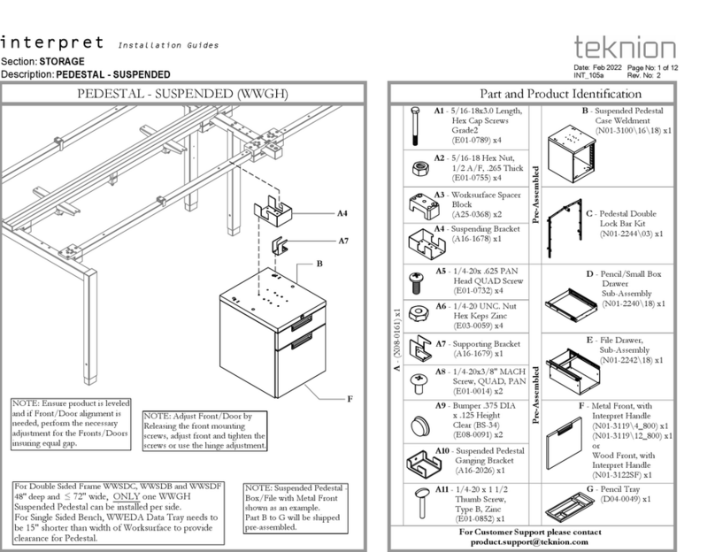
Teknion Interpret Operating and maintenance instructions
Teknion

Teknion Interpret Operating and maintenance instructions
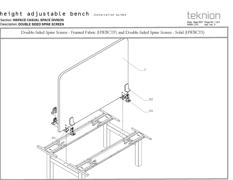
Teknion HWBCTF User manual

Teknion

Teknion HWBCTF User manual

Teknion INTERPRET WORK TABLE Operating and maintenance instructions

Teknion

Teknion INTERPRET WORK TABLE Operating and maintenance instructions

Teknion WWComplements WWCOMP HA Operating and maintenance instructions

Teknion

Teknion WWComplements WWCOMP HA Operating and maintenance instructions

Teknion Dossier ZJRP Operating and maintenance instructions

Teknion

Teknion Dossier ZJRP Operating and maintenance instructions

Teknion hiSpace User manual

Teknion

Teknion hiSpace User manual
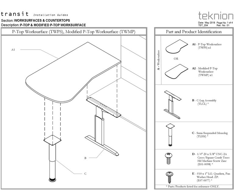
Teknion hiSpace User manual

Teknion

Teknion hiSpace User manual

Teknion transit Operating and maintenance instructions
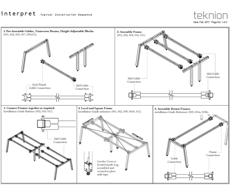
Teknion

Teknion transit Operating and maintenance instructions

Teknion Interpret User manual

Teknion

Teknion Interpret User manual
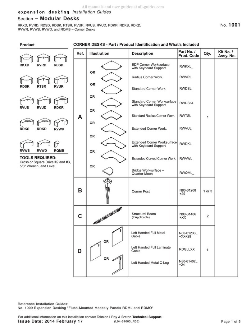
Teknion RKXD Operating and maintenance instructions
Teknion

Teknion RKXD Operating and maintenance instructions

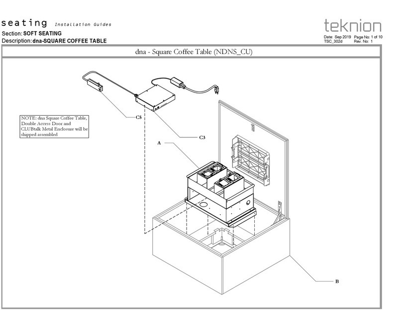
Teknion dna-SQUARE COFFEE TABLE User manual
Teknion

Teknion dna-SQUARE COFFEE TABLE User manual

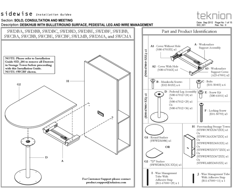
Teknion Sidewise SWDBA User manual

Teknion

Teknion Sidewise SWDBA User manual
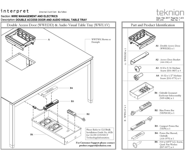
Teknion Interpret Operating and maintenance instructions

Teknion

Teknion Interpret Operating and maintenance instructions

Teknion PUNT Stockholm Storage Operating and maintenance instructions

Teknion

Teknion PUNT Stockholm Storage Operating and maintenance instructions
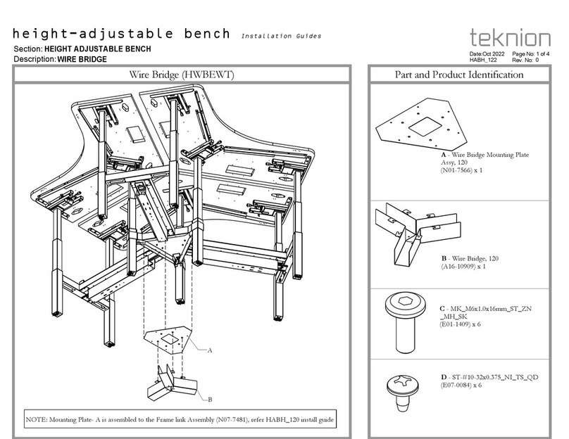
Teknion HWBEWT Operating and maintenance instructions

Teknion

Teknion HWBEWT Operating and maintenance instructions
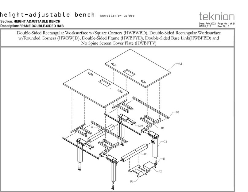
Teknion HWBWBD User manual

Teknion

Teknion HWBWBD User manual

Teknion interpret WWSDC Operating and maintenance instructions
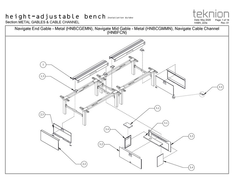
Teknion

Teknion interpret WWSDC Operating and maintenance instructions

Teknion Height-adjustable bench Operating and maintenance instructions

Teknion

Teknion Height-adjustable bench Operating and maintenance instructions
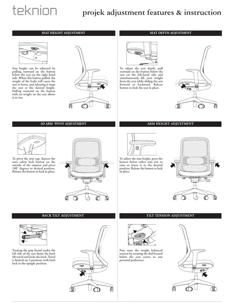
Teknion Projek Owner's manual

Teknion

Teknion Projek Owner's manual
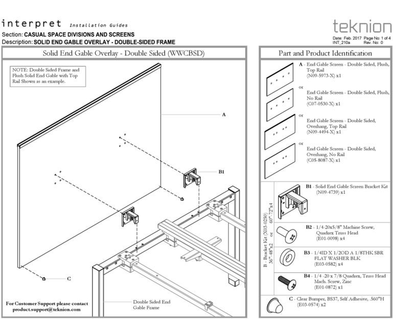
Teknion interpret WWCBSD Operating and maintenance instructions

Teknion

Teknion interpret WWCBSD Operating and maintenance instructions

Teknion Synapse Wood Guest Chair NSYN Operating and maintenance instructions

Teknion

Teknion Synapse Wood Guest Chair NSYN Operating and maintenance instructions

Teknion Marini Owner's manual

Teknion

Teknion Marini Owner's manual

Teknion Interpret User manual

Teknion

Teknion Interpret User manual

Teknion Single-Sided Rectangular Worksurface User manual

Teknion

Teknion Single-Sided Rectangular Worksurface User manual

Popular Indoor Furnishing manuals by other brands

Seconique 55049 Assembly instructions

Seconique

Seconique 55049 Assembly instructions

American Standard Town Square Wall Sconce 2555.081 installation instructions

American Standard

American Standard Town Square Wall Sconce 2555.081 installation instructions

Greentouch 1030FM-28-227 Assembly / care & use instructions
Greentouch

Greentouch 1030FM-28-227 Assembly / care & use instructions

Donco PRINCETON STAIR BUNK 2204 Assembly instructions

Donco

Donco PRINCETON STAIR BUNK 2204 Assembly instructions

Songmics LBS04 manual

Songmics

Songmics LBS04 manual

SUNON UP1 Assembly instruction

SUNON

SUNON UP1 Assembly instruction

DETAIL Fox Brooklyn II manual

DETAIL

DETAIL Fox Brooklyn II manual

Maintal Yanis Assembly instructions

Maintal

Maintal Yanis Assembly instructions

JWA OTTAWA 68321 Assembly instruction

JWA

JWA OTTAWA 68321 Assembly instruction

BRW ALVEO B24-RTV1D1S manual

BRW

BRW ALVEO B24-RTV1D1S manual

Sanus Systems CFAV34 instruction manual

Sanus Systems

Sanus Systems CFAV34 instruction manual

Rauch M2582 Assembly instructions

Rauch

Rauch M2582 Assembly instructions

Gautier Office 210 Assembly instructions

Gautier Office

Gautier Office 210 Assembly instructions

Coaster 206361F Assembly instructions

Coaster

Coaster 206361F Assembly instructions
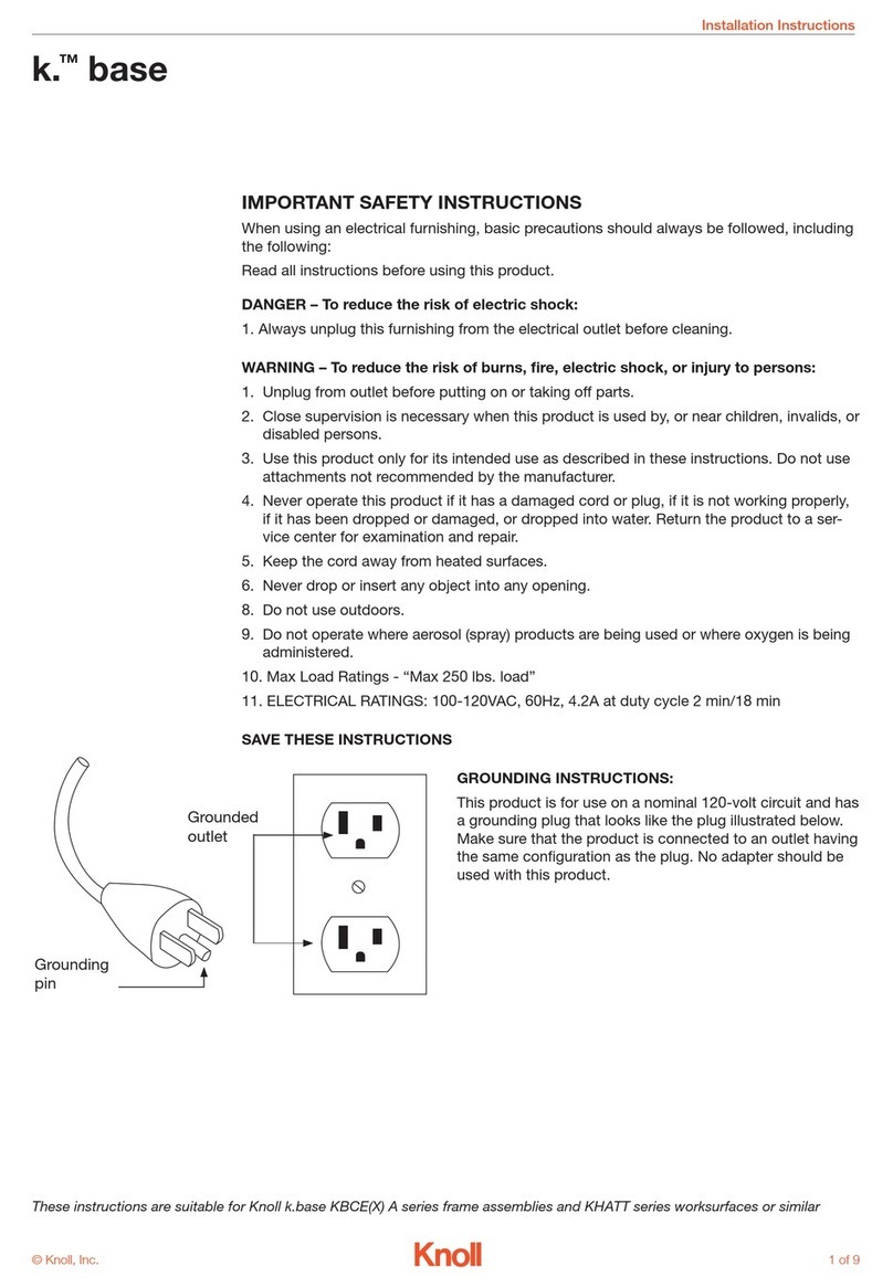
Knoll k. base installation instructions

Knoll

Knoll k. base installation instructions

IKEA BILLY BYOM GLASS 15 3/4x13 3/4" instructions

IKEA

IKEA BILLY BYOM GLASS 15 3/4x13 3/4" instructions

Monarch Specialties I 7955P Assembly instructions

Monarch Specialties

Monarch Specialties I 7955P Assembly instructions

Crosley Catalina CO7120-BR quick start guide

Crosley

Crosley Catalina CO7120-BR quick start guide

manuals.online logo
manuals.online logoBrands
  • About & Mission
  • Contact us
  • Privacy Policy
  • Terms and Conditions

Copyright 2025 Manuals.Online. All Rights Reserved.