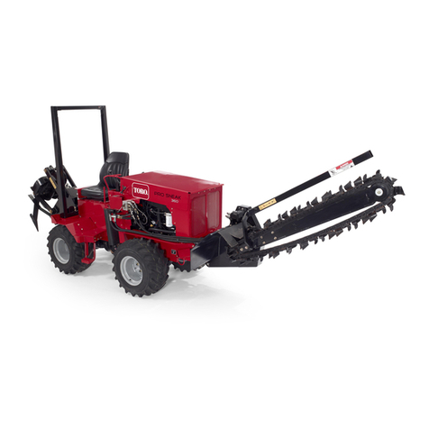
Toro Outcross 9060 Series User manual

FormNo.3433-349RevA
CargoBed
Outcross9060SeriesTractionUnit
ModelNo.07530
InstallationInstructions
Safety
SafetyandInstructionalDecals
Safetydecalsandinstructionsareeasilyvisibletotheoperatorandarelocatednearanyarea
ofpotentialdamage.Replaceanydecalthatisdamagedormissing.
decal93-9852
93-9852
1.Warning—readtheOperator’sManual.2.Crushinghazard—installthecylinderlock.
93-9899
decal93-9899
93-9899
1.Crushinghazard—installthecylinderlock.
decal105-4215
105-4215
1.Warning—avoidpinchpoints.
decal115-7739
115-7739
1.Falling,crushinghazard—donotcarrypassengers.
decal138-4107
138-4107
1.Crushinghazardofthehand—keephandsawayfromthe
pinchpoint.
©2019—TheToro®Company
8111LyndaleAvenueSouth
Bloomington,MN55420
Registeratwww.Toro.com.OriginalInstructions(EN)
PrintedintheUSA
AllRightsReserved*3433-349*A

decal138-8166
138-8166
1.Attention—read
theOperator’s
Manualbefore
performing
maintenance.
5.Removethe
rod.
9.Raisethebed
usingajack.
2.Keep
bystanders
away.
6.Lowerthebed.10.Slowlydrive
forward.
3.Raisethebed.7.Removethe
quick-release
pin.
11.Disconnect
thehydraulic
hoses.
4.Rotatetheleg
forward.
8.Removethe
lanyard.
12.Disconnectthe
wireharness.
2

Installation
LooseParts
Usethechartbelowtoverifythatallpartshavebeenshipped.
ProcedureDescriptionQty.Use
1Nopartsrequired–Preparethemachine.
2Nopartsrequired–Removethestandardbedanddrawbar.
Leftpivotbracket1
Rightpivotbracket1
Capscrew(1/2x1-3/4inches)8
3Flangelocknut(1/2inch)8
Installthepivotbrackets.
Cylinderliftassembly1
4Flange-headcapscrew(1/2x1-3/4
inches)2Installthecylinderlift.
Hydrauliccylinderandhoses1
Cylinderpin1
5Lynchpin2
Assemblethehydrauliccylindertothe
machine.
Lanyardbracket1
Flange-headcapscrew(1/2x1-1/4
inches)2
6Flangelocknut(1/2inch)2
Installthelanyardbracket.
Proximity-sensorjumper1
7Cabletie1Installtheproximity-sensorjumper.
Cargobed1
Pushrod1
Lanyard1
Shoulderbolt2
Flangelocknut(5/16inch)9
Wingnut1
Forwardpanel1
Carriagebolt(5/16x2-1/2inches)4
Carriagebolt(5/16x2-3/4inches)2
Mudap2
Capscrew(5/16x1inch)8
8
Washer(5/16x1-1/2inches)8
Assemblethecargobed.
Mudap2
Capscrews(5/16x1inch)6
9Washers(5/16x1-1/2inches)6
Installtheforwardbedhardwareand
mudaps.
3

1
PreparingtheMachine
NoPartsRequired
Procedure
1.Removeanyrearattachments,theloaderand
ballastbox;refertotheinstallationinstructions
foryourattachmentsortheOperator’sManual
foryourtractionunit.
2.Parkthemachineonalevelsurfaceandmove
theshiftlevertotheNEUTRALposition.
3.Fullylowerthe3-pointhitch;refertothe
Operator’sManualforyourtractionunit.
4.Engagetheparkingbrake,shutofftheengine,
removethekey,andwaitforallmovementto
stopbeforeyouleavetheoperator’sposition.
2
RemovingtheStandard
Bed,Drawbar,andTopLink
NoPartsRequired
Procedure
Removethestandardbed,drawbar,andtoplink;
refertotheOperator’sManualforyourtractionunit.
3
InstallingthePivotBrackets
Partsneededforthisprocedure:
1Leftpivotbracket
1Rightpivotbracket
8Capscrew(1/2x1-3/4inches)
8Flangelocknut(1/2inch)
Procedure
1.Identifytheleftandrightpivotbracketsasshown
inFigure1.
g258968
Figure1
1.Leftpivotbracket2.Rightpivotbracket
2.Removethe2capscrews(1x1-1/4inches)
and2angelocknuts(1/2inch)thatsecure
thebulkheadplatefortherear,hydraulic
quick-connectcouplingstotheright,rearframe
gusset(Figure2).
4

g287289
Figure2
1.Capscrew(1x1-1/4
inches)
3.Bulkheadplate(rear
hydraulicquick-connect
couplings)
2.Framegusset(rightrear)4.Flangelocknut(1/2inch)
3.Aligntheholesintheleftpivotbracketwiththe
holesinthegussetplateattheleftframerail
(Figure3).
g258969
Figure3
1.Capscrew(1/2x1-3/4
inches)
4.Flangelocknut(1/2inch)
2.Gussetplate(leftframe
rail)
5.Rightpivotbracket
3.Leftpivotbracket
4.Assemblethepivotbrackettothegussetplate
with4capscrews(1/2x1-3/4inches)and4
angelocknuts(1/2inch).
5.Torquethecapscrewsandnutsto91to113N∙m
(67to83ft-lb).
6.Aligntheholesintherightpivotbracketwiththe
holesinthegussetplateandbulkheadplateat
therightframerail(Figure3).
7.Repeatsteps4and5fortherightpivotbracket.
4
InstallingtheCylinderLift
Partsneededforthisprocedure:
1Cylinderliftassembly
2Flange-headcapscrew(1/2x1-3/4inches)
Procedure
1.Removethetop2ange-headcapscrews(1/2
x1-1/2inches)andtop2angelocknuts(1/2
inch)thatsecurethelink-attachbrackettothe
frameofthemachine(Figure4).
Note:Younolongerneedthe2ange-head
capscrews(1/2x1-1/2inches).
g286329
Figure4
1.Flangelocknut(1/2inch)3.Flange-headcapscrews
(1/2x1-1/2inches)
2.Link-attachbracket
2.Aligntheholesinthecylinderliftwiththeholes
intheframeofthemachineandlink-attach
bracketasshowninFigure5.
5

g290078
Figure5
1.Flangelocknut(1/2inches)3.Flange-headcapscrew
(1/2x1-3/4inch)
2.Cylinderlift
3.Assemblethecylinderlifttotheframeofthe
machineandlink-attachbracketwith2ange
locknut(1/2inches)thatyouremovedinstep1
andthe2ange-headcapscrews(1/2x1-3/4
inch)asshowninFigure5.
4.Torquethecapscrewsandlocknutsto91to113
N∙m(67to83ft-lb).
5
AssemblingtheHydraulic
CylindertotheMachine
Partsneededforthisprocedure:
1Hydrauliccylinderandhoses
1Cylinderpin
2Lynchpin
AssemblingtheHydraulicCylinder
totheMachine
1.Removethe3ange-headboltsthatsecurethe
drive-shaftcovertothemachine,andremove
thecover(Figure6).
g258980
g258955
Figure6
1.Flange-headbolts(5/16x
3/4inch)
2.Drive-shaftcover
2.Assemblethestationaryendofthehydraulic
cylindertothecylindersupportwiththecylinder
pinand2lynchpins(Figure7).
g260027
Figure7
1.Lynchpin3.Cylindersupport
2.Hydrauliccylinder4.Cylinderpin
3.Assemblethedrive-shaftcovertothechassisof
themachinewiththe3ange-headbolts(5/16x
3/4inch)thatyouremovedinstep1.
6

g260058
Figure8
1.Flange-headbolts(5/16x
3/4inch)
2.Drive-shaftcover
ConnectingtheHydraulicHoses
1.Routethe2hydraulichosestothequick-connect
panelfortherearattachmentsasshownin
Figure9.
Note:Ensurethatthereisclearancebetween
thehydraulichosesandrotatingorhot
componentsofthetractorortractionunit.
g260110
Figure9
1.Retracthose3.Quick-connectpanel
2.Extendhose
2.Identifythequick-disconnectttingsforthe
rearattachment-liftandlowercircuitsforthe
machine.
3.Removethedustcoversforthequick-connect
ttingsofthehydraulichosesandthecapsof
themachine(Figure10).
g290080
Figure10
1.Quick-connecttting
(extendhydraulic
hose—reddustcap)
3.Quick-connecttting
(retracthydraulic
hose—blackdustcap)
2.Quick-connectcoupling
(rearattachment-extend
circuit—reddustplug)
4.Quick-connectcoupling
(rearattachment-retract
circuit—blackdustcap)
4.Plugthequick-connectttingfortheretracthose
(withtheblackdustcap)intothequick-connect
couplingfortherearattachment-retractcircuit
(bottomport—withtheblackdustcap)asshown
inFigure10.
5.Plugthequick-connectttingfortheextendhose
(withthereddustcap)intothequick-connect
couplingfortherearattachment-extendcircuit
(topport—withthereddustcap)asshownin
Figure10.
6
InstallingtheLanyard
Bracket
Partsneededforthisprocedure:
1Lanyardbracket
2Flange-headcapscrew(1/2x1-1/4inches)
2Flangelocknut(1/2inch)
Procedure
1.Attheleftpivotbracketforthecargobed,align
theholesinthelanyardbracketwiththeholesin
theleftframechannelasshowninFigure11.
7

g286413
Figure11
1.Flangelocknut(1/2inch)4.Leftframechannel
2.Leftpivotbracket(cargo
bed)
5.Lanyardbracket
3.Flange-headcapscrew
(1/2x1-1/4inches)
2.Securethebrackettotheframe(Figure11)with
2ange-headcapscrews(1/2x1-1/4inches)
and2angelocknuts(1/2inch).
3.Torquethecapscrewsandnutsto91to113N∙m
(67to83ft-lb).
7
Installingthe
Proximity-SensorJumper
Partsneededforthisprocedure:
1Proximity-sensorjumper
1Cabletie
Procedure
Important:Theproximity-sensorjumperlimits
themaximumheightofthe3-pointhitch.
Installtheproximity-sensorjumpertoprevent
accidentallydamagingthecargoboxwiththe
3-pointhitch.
1.Attherightframechannelofthemachine,
removetheplugfromthe3-pinconnectorofthe
wireharnesslabeledBEDREARDOWN(Figure
12).
g286414
Figure12
1.Plug5.Backofthemachine
2.3-pinconnector(BEDREAR
DOWN)
6.Hydraulictube
3.Proximity-sensorjumper7.Cabletie
4.Rightframerail
2.Inserttheproximity-sensorjumperintothe3-pin
connector(Figure12).
3.Securetheproximity-sensorjumpertothe
hydraulictubewithacabletie(Figure12).
8

8
AssemblingtheCargoBed
Partsneededforthisprocedure:
1Cargobed
1Pushrod
1Lanyard
2Shoulderbolt
9Flangelocknut(5/16inch)
1Wingnut
1Forwardpanel
4Carriagebolt(5/16x2-1/2inches)
2Carriagebolt(5/16x2-3/4inches)
2Mudap
8Capscrew(5/16x1inch)
8Washer(5/16x1-1/2inches)
AssemblingtheCargoBedtothe
Hinges
Liftingequipmentcapacity:300kg(660lb)
1.Useliftingequipmenttoalignthecargobedto
theframeofthemachinewiththejackatthe
backofthemachine(Figure13).
g260065
Figure13
2.Alignthehingepinsofthecargobedwiththe
pivotbrackets,andlowerthebed(Figure14).
g260111
Figure14
1.Hingepins(cargobed)2.Pivotbrackets
3.Atthebackofthemachine,securethecargo
bedtothepivotbracketswith2quick-release
pins(Figure15).
g286494
Figure15
1.Quick-releasepins3.Bed-pivotstraps
2.Pivotbracket
9

InstallingthePushRodtothe
CargoBed
1.Usetheliftingequipmenttotiltthecargobedso
thatyoucanaccessthebedstraps.
2.Attheleftsideofthecargobed,assemblethe
pushrodthroughtheovalopeningsinthe2left
bed-pivotstraps(Figure16).
g290082
Figure16
1.Bed-pivotstraps(leftside
ofthecargobed)
2.Pushrod
3.Alignthebedpinattheendofthepushrodwith
theslotintheleftliftplate(Figure17).
g290081
Figure17
1.Liftplate(left)2.Bedpin(pushrod)
AssemblingtheHydraulicCylinder
totheCargoBed
1.Haveanotherpersonstarttheengineandmove
theauxiliary-hydraulicleverrearwardtoextend
therodendofthehydrauliccylinder(Figure18).
g290083
Figure18
1.Floatposition(detent)3.Cylinderextend(raisethe
bed)
2.Cylinderretract(lowerthe
bed)
4.Auxiliary-hydrauliclever
g260112
Figure19
1.Hydraulic-cylinderrod2.Slot(bed-liftplate)
2.Whentheholeinthehydraulic-cylinderrod
alignswiththeslotsinthebed-liftplate,movethe
auxiliary-hydrauliclevertotheneutralposition,
shutofftheengine,andremovethekey.
3.Movethepushrodinwardtosecurethe
hydrauliccylindertotheliftplate,androtatethe
pushrodcounterclockwisesothatthehandle
restsonthelockplate(Figure20).
10

g260114
Figure20
1.Lockplate2.Pushrod
Important:Ensurethatthebedpinatthe
endofthepushrod(Figure21)extends
throughtheslotintherightliftplate.
g290084
Figure21
1.Liftplate(right)3.Rightsideofthemachine
2.Bedpin
InstallingtheCargoBedLanyard
totheBracket
1.Alignthewingnutattheendofthelanyardwith
theslotsinthelanyardbracket(Figure22).
g290085
g286524
Figure22
1.Lanyardbracket3.Lanyard
2.Wingnut
2.Insertthewingnutthroughtheslotsinthe
bracket(Figure22).
3.Alignthewingnut,shoulderboltandlanyard
downinthelowerslotinthebracket(Figure22).
4.Removetheliftingequipmentfromthecargo
bed.
5.Starttheengine,movetheauxiliaryhydraulic
leverforwardtolowerthecargobed(Figure18),
shutofftheengineandremovethekey.
InstallingtheRearMudFlaps
1.Assembleamudaptothemudapbracket
with4capscrews(5/16x1inch)and4washers
11

(5/16x1-1/2inches),andtightenthecapscrews
byhand(Figure23).
g260221
Figure23
1.Capscrew(5/16x1inch)3.Mudap
2.Washer(5/16x1-1/2
inches)
4.Clipnut
2.Repeatstep1forthemudapattheotherside
ofthemachine.
9
InstallingtheForwardMud
Flaps
Partsneededforthisprocedure:
2Mudap
6Capscrews(5/16x1inch)
6Washers(5/16x1-1/2inches)
Procedure
1.Starttheengine,fullyraisethebed,shutoffthe
engine,andremovethekey.
2.Installthecylinderlock;refertoInstallingthe
CylinderLock(page14).
3.Assembleamudaptotheforwardangeofthe
receiver(Figure24)with4capscrews(5/16x1
inch)and4washers(5/16x1-1/2inches).
g260208
Figure24
1.Capscrew(5/16x1inch)3.Mudap
2.Washer(5/16x1-1/2
inches)
4.Nutclip
4.Repeatstep3fortheforwardmudapatthe
othersideofthemachine.
5.Stowthecylinderlock;refertoStowingthe
CylinderLock(page15).
6.Starttheengine,lowerthecargobed,shutoff
theengine,andremovethekey.
12

ProductOverview
Specications
Widthx185cm(52
inches)
Length132cm(73
inches)
Interiordimensions
Height40cm(16inches)
Cargoboxload2041kg(4,500lb)
Operation
OpeningtheTailgate
1.Pullthetailgate-latchhandle(Figure25).
g260316
Figure25
2.Rotatetheretainerawayfromthelatchpin
(Figure25).
3.Repeatsteps1and2forthetailgatelatchatthe
othersideofthemachine.
4.Lowerthetailgate.
RaisingtheCargoBed
Movetheauxiliaryhydraulicleverrearwardtoraise
thecargobed(Figure26).
g290083
g260317
Figure26
1.Floatposition(detent)3.Cylinderextend(raisethe
bed)
2.Cylinderretract(lowerthe
bed)
4.Auxiliary-hydrauliclever
13

LoweringtheCargoBed
CAUTION
Movingtheauxiliaryhydrauliclevertothe
oatpositionwhenthecargo-bedloadis
behindthehingesmaycausethebedtorotate
backwardunexpectedly(Figure27).
Movetheauxiliaryhydraulicleveronlytothe
cylinderretractpositionwhenloweringthe
cargobed.
g287312
Figure27
Movetheauxiliaryhydraulicleverforwardtolower
thecargobed;refertoFigure26inRaisingtheCargo
Bed(page13).
InstallingtheCylinderLock
1.Unloadthecargobox.
2.Engagetheparkingbrake,fullyraisethecargo
bed,shutofftheengine,removethekey,and
waitforallmovementtostopbeforeyouleave
theoperator’sposition.
3.Removethathairpinandclevispinthatsecure
thecylinderlocktothebottomoftheouter,right
bed-pivotstrapofthecargobed(Figure28).
g286561
Figure28
1.Clevispin3.Hairpin
2.Outer,rightbed-pivotstrap4.Cylinderlock
4.Alignthecylinderlockovertherodofthe
hydrauliccylinder(Figure29).
g286560
Figure29
1.Clevispin3.Hydrauliccylinderrod
2.Cylinderlock4.Hairpin
5.Securethecylinderlocktothecylinderrodwith
theclevispinandhairpin(Figure29).
14

StowingtheCylinderLock
1.Removethehairpinandclevispinthatsecures
thecylinderlocktothecylinderrod(Figure30).
g286562
Figure30
1.Clevispin3.Hydrauliccylinderrod
2.Cylinderlock4.Hairpin
2.Aligntheholesinthecylinderlockgrommets
withtheholeintheouter,rightbed-pivotstrapof
thecargobed(Figure31).
g286563
Figure31
1.Clevispin3.Hairpin
2.Outer,rightbed-pivotstrap4.Cylinderlock
3.Securethecylinderlocktothestrapwiththe
clevispinandhairpin(Figure31).
RemovingtheCargoBed
PreparingtoRemovetheCargo
Bed
1.Unloadthatcargobedandlatchthetailgate.
2.Movethemachinetoalevelsurface.
3.Ifinstalled,lowerthe3-pointhitchtothelowest
position(Figure32).
g290086
Figure32
4.Shutofftheengineandengagetheparking
brake.
5.Removethehairpinandclevispinthatsecure
thedrawbartothedraw-barsupport,and
removethedrawbar(Figure33).
g290276
Figure33
1.Clevispin3.Hairpin
2.Draw-barsupport4.Drawbar
15

RemovingtheJackandRear
Cargo-BedLeg
1.Atthebackofthecargobed,removethe
self-lockingpinthatsecuresthejacktotherear
cargo-bedleg,andremovethejackfromthe
cargo-bedleg(Figure34).
g261938
g261936
Figure34
1.Rearcargo-bedleg2.Jack
2.Removetheself-lockingpinthatsecuresthe
rearcargo-bedlegtothejackbracketofthe
cargobed(Figure35).
g260233
Figure35
1.Self-lockingpin3.Rearcargo-bedleg
2.Jackbracket(cargobed)
DisconnectingtheHydraulic
CylinderfromtheCargoBed
1.Starttheengine,fullytiltthecargobed,andshut
offtheengine(Figure36);refertoRaisingthe
CargoBed(page13).
g261939
Figure36
2.Rotatethepushrodclockwisetoclearthelock
plate(Figure37).
g261953
Figure37
1.Hydrauliccylinderrod3.Bedpin(pushrod)
2.Slot(bed-liftplate)4.Lockplate
3.Pullthepushroduntilthebedpinclearstheslot
inthebed-liftplate(Figure37).
4.Starttheengine,fullyretractthehydraulic
cylinder,andshutofftheengine.
16

ExtendingtheForwardCargo-Bed
Legs
1.Removetheself-lockingpinthatsecuresthe
forwardcargo-bedlegtothereceiver(Figure
38).
g261941
Figure38
1.Self-lockingpin3.Receiver(cargo-bedleg)
2.Forwardcargo-bedleg
2.Removethecargo-bedlegfromthereceiverand
rotateitdown90°(Figure38).
3.Insertthecargo-bedlegintothereceiverand
securethelegwiththeself-lockingpinasshown
inFigure38.
4.Repeatsteps1through3fortheforward
cargo-bedlegattheothersideofthemachine.
5.Tiltthecargobedbyhandisuntilthefrontlegs
contacttheground.
g261942
Figure39
DisconnectingtheLanyard
1.Movethewingnut,shoulderboltandlanyardup
intheslotinthelanyardbracket(Figure40).
g286745
Figure40
1.Lanyardbracket3.Lanyard
2.Shoulderboltandwingnut
2.Movethewingnutoutthroughtheslotsinthe
bracket(Figure40).
17

SeparatingtheCargoBedfrom
theMachine
1.Atthebackofthemachine,removethe2
quick-releasepinsthatsecurethecargobedto
thepivotbrackets(Figure41).
g286494
Figure41
1.Quick-releasepins3.Bed-pivotstraps
2.Pivotbracket
2.Inserttherearcargo-bedlegintotherear-leg
receiver(Figure42).
g262016
Figure42
1.Rear-legreceiver3.Rearcargo-bedleg
2.Quick-releasepin
3.Securethelegtothereceiverwiththe
quick-releasepin(Figure42).
4.Ensurethatthejackisfullycompressed,
assemblethejacktothebackoftherear
cargo-bedlegtube,andsecurethejacktothe
legwiththeself-lockingpin(Figure43).
g262020
Figure43
1.Tube(rearcargo-bedleg)2.Jack
5.Raisethecargobedwiththejackuntilthejack
isfullyextended(Figure44).
g262018
Figure44
6.Carefullydrivethetractionunitawayfromthe
cargobed(Figure45).
g262021
Figure45
7.Parkthemachine,engagetheparkingbrake,
shutofftheengine,andwaitforallmovement
tostop.
18

DisconnectingtheCargoBed
HydraulicHoses
1.Movetheauxiliaryhydraulicleverfullforward
(FLOAT)positiontorelievepressure,andthen
rearwardtothecenterNEUTRALposition(Figure
46).
g290083
Figure46
1.Floatposition(detent)3.Cylinderextend(raisethe
bed)
2.Cylinderretract(lowerthe
bed)
4.Auxiliary-hydrauliclever
2.Disconnectthehosesforthehydrauliccylinder
(Figure47)fromthequick-disconnectttingsof
themachine.
g290080
Figure47
1.Quick-connecttting
(extendhydraulic
hose—reddustcap)
3.Quick-connecttting
(retracthydraulic
hose—blackdustcap)
2.Quick-connectcoupling
(rearattachment-extend
circuit—reddustplug)
4.Quick-connectcoupling
(rearattachment-retract
circuit—blackdustcap)
3.Assemblethedustcoverontothe
quick-disconnectttings(Figure47)and
stowthehosesalongsidethecylinder.
RemovingtheProximity-Sensor
Jumper
1.Attherightframechannelofthemachine,
removetheproximity-sensorjumperfromthe
3-pinconnectorofthewireharnesslabeledBED
REARDOWN(Figure48).
g286749
Figure48
1.Proximity-sensorjumper3.Plug
2.3-pinconnector(BEDREAR
DOWN)
2.Inserttheplugintothe3-pinconnector(Figure
48).
Installingthe3-PointLiftLinkages
Ifremoved,installthelinkagesforthe3-pointlift;refer
totheInstallingtheSway,Draft,andLiftLinksinthe
Operator’sManualforyourtractionunit.
19

MountingtheCargoBed
PreparingtoMounttheCargoBed
1.Parkthemachineonalevelsurface,movethe
shiftlevertotheNEUTRALposition.
2.Ifinstalled,removeanyrearattachments
ortheloaderandballastbox;refertothe
installationinstructionsforyourattachmentsor
theOperator’sManualforyourtractionunit.
3.Fullylowerthe3-pointhitch;refertothe
Operator’sManualforyourtractionunit.
4.Engagetheparkingbrake.
InstallingtheProximity-Sensor
Jumper
Important:Installtheproximity-sensorjumperto
preventaccidentallydamagingthecargoboxwith
the3-pointhitch.
1.Attherightframechannelofthemachine,
removetheplugfromthe3-pinconnectorofthe
wireharnesslabeledBEDREARDOWN(Figure
49).
g286750
Figure49
1.Plug3.Proximity-sensorjumper
2.3-pinconnector(BEDREAR
DOWN)
2.Inserttheproximity-sensorjumperintothe3-pin
connector(Figure49).
AssemblingtheCargoBedtothe
Machine
1.Raisethecargobedwiththejackuntilthejack
isfullyextended(Figure50).
g263287
Figure50
1.Jack
2.Alignthetractionunitbetweenthefrontlegsof
thecargobed(Figure50).
3.Carefullybackthetractionunitunderthecargo
beduntilthepivotbracketsalignbelowthehinge
pinsofthecargobed(Figure51).
g260111
Figure51
1.Hingepins(cargobed)2.Pivotbrackets
4.Engagetheparkingbrake,shutofftheengine,
andremovethekey.
20
Other manuals for Outcross 9060 Series
2
This manual suits for next models
1
Table of contents
Other Toro Farm Equipment manuals

Toro
Toro Dingo TX 22306 User manual

Toro
Toro 41216 User manual

Toro
Toro 25464 User manual

Toro
Toro Sand Pro 5040 User manual

Toro
Toro Sand Pro 2040Z User manual

Toro
Toro VS-400 User manual

Toro
Toro Reelmaster 33455 User manual

Toro
Toro MB-1600 User manual

Toro
Toro 03621 User manual

Toro
Toro Workman 3000 Series User manual

Toro
Toro 23106 User manual

Toro
Toro Multi Pro 1200 User guide

Toro
Toro ProCore SR Series User manual

Toro
Toro Groundsmaster 4500-D User manual

Toro
Toro 133-6314 User manual
Toro
Toro Pro Sneak 360 User manual

Toro
Toro 41614 User manual

Toro
Toro 2226 Quick start guide

Toro
Toro 41245 User manual

Toro
Toro 31526 User manual