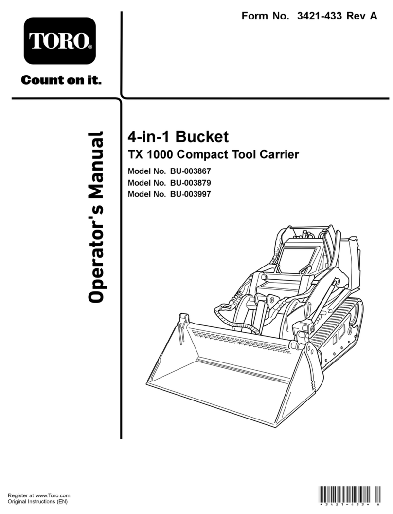
Toro 03667 User manual
Other Toro Tractor Accessories manuals
Toro
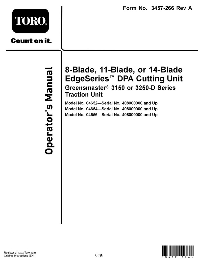
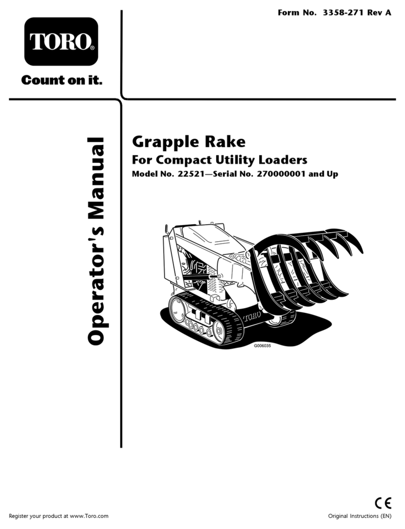
Toro 22521 User manual
Toro
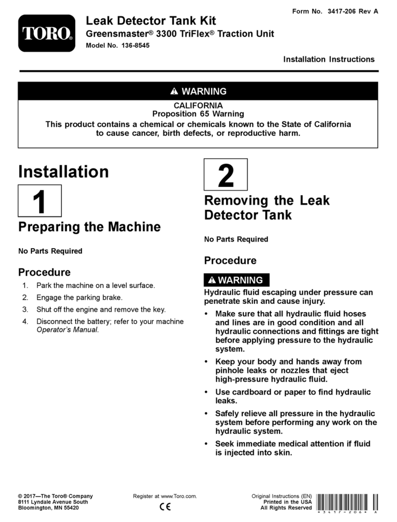
Toro 136-8545 User manual

Toro
Toro Field Pro 604 User manual

Toro
Toro Z MASTER 79402 User manual
Toro
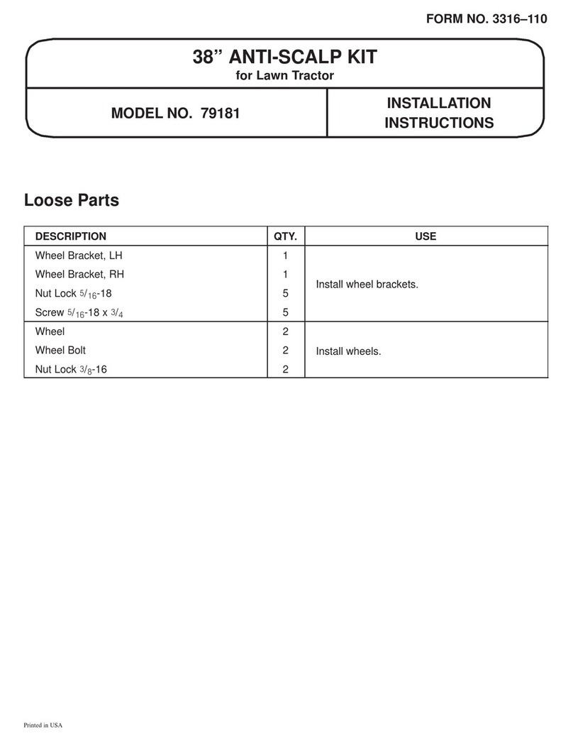
Toro 79181 User manual
Toro
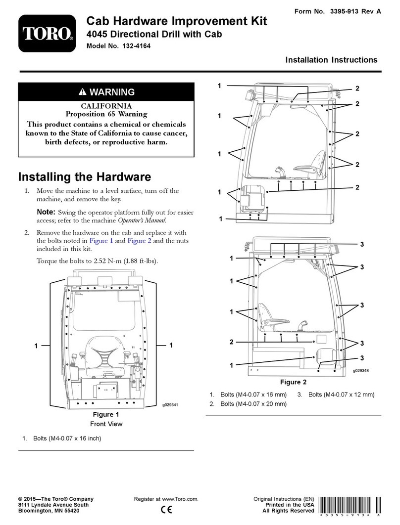
Toro 132-4164 User manual

Toro
Toro Greensmaster TriFlex 3300 Series User manual

Toro
Toro 04720 User manual

Toro
Toro Direct Drive Power Box Rake User manual
Toro
Toro 79362 User manual

Toro
Toro 30728 User manual
Toro
Toro 04651 User manual

Toro
Toro 04504 User manual

Toro
Toro 22414 User manual

Toro
Toro 119-9604 User manual

Toro
Toro Wheel Horse 79361 User manual
Toro
Toro Sitework Systems 22420 User manual
Toro
Toro 111-6032 User manual
Toro
Toro Wheel Horse XT Series User manual
Toro
Toro 04479 User manual
Popular Tractor Accessories manuals by other brands

Original Tractor Cabs
Original Tractor Cabs 4421381 Assembly instructions and parts list

Grouser Products
Grouser Products 760 Owner's manual & parts book

Degelman
Degelman Landroller Operator's & parts manual

Bush Hog
Bush Hog BS1 Series Operator's manual

MX
MX MX A104 user manual
Bush Hog
Bush Hog DSP8 Operator's manual
