TFP1515
Page 3 of 4
damage the seat material. Be sure to
center the valve and do not damage
the liner. Relax the separation of the
anges, install, and hand-tighten all
ange bolts. Slowly open the valve,
checking for free movement of the disc.
If valve opens freely, leave the valve in
the open position, and using a cross-
draw sequence, tighten all ange bolts
until the valve is metal-to-metal with
both mating anges. Recommended
tightening torques are listed in Table A.
Be certain to keep ange faces as paral-
lel as possible during and after tighten-
ing bolts or studs. After nal tightening,
again check the valve for full opening
and closing.
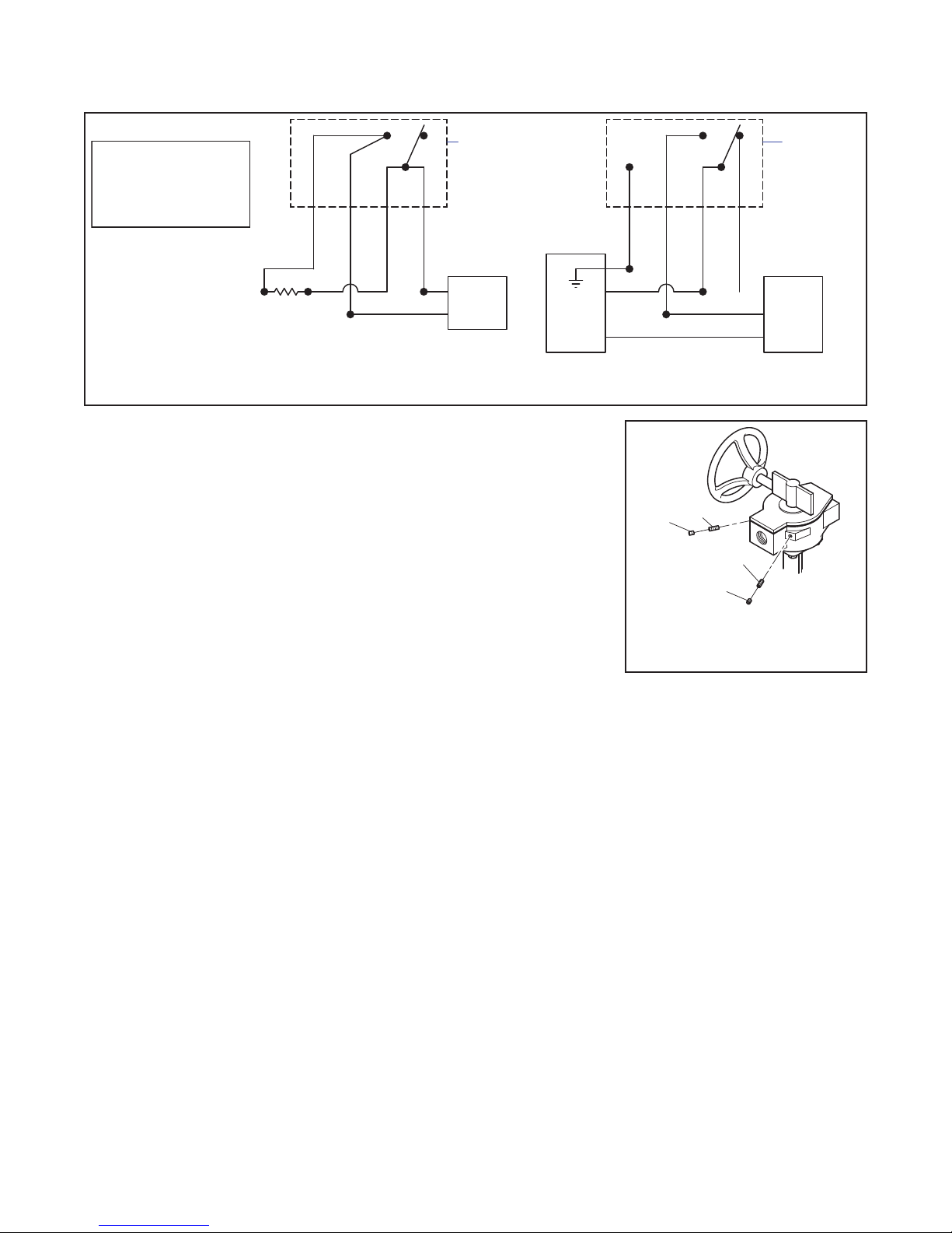
As applicable, refer to Figure 2 for the
internal switch wiring diagram.
Conduit and electrical connections
are to be made in accordance with the
authority having jurisdiction and/or the
National Electrical Code. With reference
to Figure 2, the supervisory switch is
intended for connection to the supervi-
sory circuit of a re alarm control panel
in accordance with NFPA 72. The auxil-
iary switch is intended for the unsuper-
vised connection to auxiliary equipment
in accordance with NFPA 70, National
Electric Code.
NOTE: For outdoor applications with
internal supervisory switches, it is rec-
ommended that wiring connections
be made at a temperature above 15°F
(-9°C), in order to insure sufficient flex-
ibility of the wire lead insulation.
Stop Adjustment Procedure
The gear operator’s OPEN and SHUT
position have been factory set. The
following procedure should be used if
slight adjustments are needed. Refer to
Figure 3.
Step 1. Turn the Handwheel until the
valve is fully closed.
Step 2. Remove the two Lock Screws
(A) from the gear operator body.
Step 3. Turn the Shut Stop Screw (B)
clockwise until snug.
Step 4. Turn the Handwheel until the
valve is fully open.
Step 5. Turn the Open Stop Screw (C)
clockwise until snug.
Step 6. Close the valve by turning the
Handwheel until the valve is fully in
the closed position. Ensure the disc
has returned to the fully closed posi-
tion and the disc is centered in the seat
area. Readjust the Shut Stop Screw if
necessary.
Step 7. Replace the two Lock Screws
(A) into the gear operator body, locking
the stops into position.
Care and
Maintenance
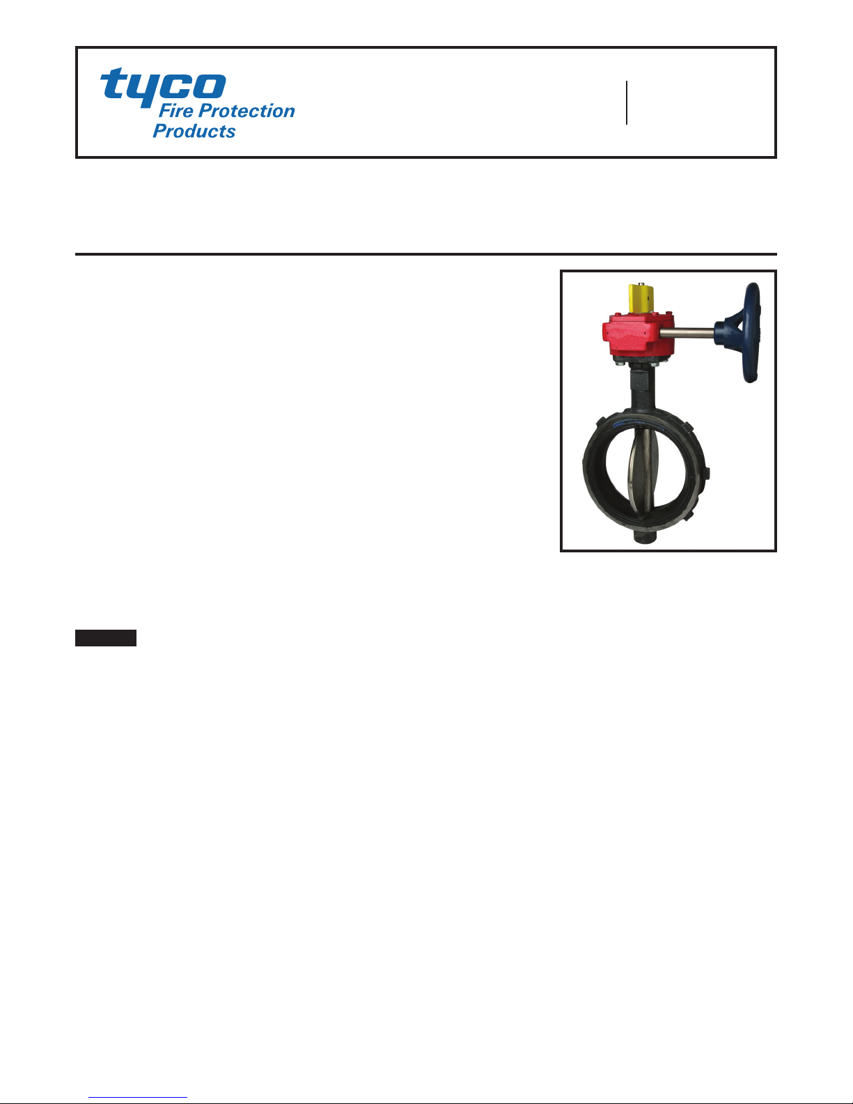
The TYCO Model BFV-N Wafer Style
Buttery Valves must be maintained
and serviced in accordance with this
section.
Before closing a re protection system
control valve for maintenance or inspec-
tion work on either the valve or re
protection system which it controls, per-
mission to shut down the affected re
protection systems must be obtained
from the proper authorities and all per-
sonnel who may be affected by this
decision must be notied.
The owner is responsible for the
inspection, testing, and maintenance of
their re protection system and devices
in accordance with the applicable stan-
dards of the National Fire Protection
Association (e.g., NFPA 25), in addi-
tion to the standards of any authority
having jurisdiction. Contact the install-
ing contractor or product manufacturer
with any questions. Any impairment
must be immediately corrected.
It is recommended that automatic
sprinkler systems be inspected, tested,
and maintained by a qualied inspec-
tion service.
1/2A @ 125 VDC
1/4A @ 250 VDC
15.1A/12HP @ 125, 250 VAC
5A @ 125 VAC "L"
END OF LINE
RESISTOR
PANEL
ORANGE
ORANGE
YELLOW
YELLOW
SUPERVISORY
SWITCH
SWITCH SHOWN
WITH VALVE
FULL OPEN
GREEN
VIOLET
AUXILIARY
WITH VALVE
FULL OPEN
BLUE
RED
BELL
SWITCH
GND
POWER
+
- -
+
CONTACT RATING:
AC
A
B
OPEN
FIGURE 2
MODEL BFV-N BUTTERFLY VALVE
INTERNAL SWITCH WIRING DIAGRAM WITH VALVE IN OPEN POSITION
FIGURE 3
MODEL BFV-N WAFER STYLE
BUTTERFLY VALVE
OPERATOR ADJUSTMENT