manuals.online logo
Brands
  1. Home
  2. •
  3. Brands
  4. •
  5. U-Line
  6. •
  7. Power Tools
  8. •
  9. U-Line H-3070 User manual

U-Line H-3070 User manual

Other manuals for H-3070

1

Other U-Line Power Tools manuals

U-Line SWINGLINE H-3067 User manual

U-Line

U-Line SWINGLINE H-3067 User manual

U-Line Shrinkfast 975 User manual

U-Line

U-Line Shrinkfast 975 User manual

U-Line H-2028 User manual

U-Line

U-Line H-2028 User manual

U-Line SWINGLINE LIGHT TOUCH H-2323 User manual

U-Line

U-Line SWINGLINE LIGHT TOUCH H-2323 User manual

U-Line H-1980 User manual

U-Line

U-Line H-1980 User manual

U-Line H-1993 User manual

U-Line

U-Line H-1993 User manual

U-Line H-738 User manual

U-Line

U-Line H-738 User manual

U-Line SHRINKFAST H-6098 User manual

U-Line

U-Line SHRINKFAST H-6098 User manual

U-Line H-1028 User manual

U-Line

U-Line H-1028 User manual

U-Line H-2027 User manual

U-Line

U-Line H-2027 User manual

U-Line H-1993 User manual

U-Line

U-Line H-1993 User manual

U-Line Н-863 User manual

U-Line

U-Line Н-863 User manual

U-Line H-491 User manual

U-Line

U-Line H-491 User manual

U-Line H-1024 User manual

U-Line

U-Line H-1024 User manual

U-Line H-1302 User manual

U-Line

U-Line H-1302 User manual

U-Line H-915 User manual

U-Line

U-Line H-915 User manual

U-Line H-2027 User manual

U-Line

U-Line H-2027 User manual

U-Line H-995 User manual

U-Line

U-Line H-995 User manual

U-Line H-3070 User manual

U-Line

U-Line H-3070 User manual

U-Line H-10157 User manual

U-Line

U-Line H-10157 User manual

U-Line H-10066 User manual

U-Line

U-Line H-10066 User manual

U-Line RIPACK 3000 User manual

U-Line

U-Line RIPACK 3000 User manual

U-Line SHRINKFAST 998 User manual

U-Line

U-Line SHRINKFAST 998 User manual

U-Line H-1030 User manual

U-Line

U-Line H-1030 User manual

Popular Power Tools manuals by other brands

ISLAND HOPPER Power Egg HT-309 operating instructions

ISLAND HOPPER

ISLAND HOPPER Power Egg HT-309 operating instructions

Sioux Tools SSR6P25 Instructions-parts list

Sioux Tools

Sioux Tools SSR6P25 Instructions-parts list

Makita HM1317C technical information

Makita

Makita HM1317C technical information

ABB Smart Tool + quick start guide

ABB

ABB Smart Tool + quick start guide

Baumr-AG BMJK-24S user manual

Baumr-AG

Baumr-AG BMJK-24S user manual

Bosch Professional GST 18 V-LI S Original instructions

Bosch

Bosch Professional GST 18 V-LI S Original instructions

Ronix RA-2702 quick start guide

Ronix

Ronix RA-2702 quick start guide

Nordson ProBlue user guide

Nordson

Nordson ProBlue user guide

aoyue int6028 instruction manual

aoyue

aoyue int6028 instruction manual

Hitachi CJ 65VA2 Instruction manual and safety instructions

Hitachi

Hitachi CJ 65VA2 Instruction manual and safety instructions

Makita HM1304 instruction manual

Makita

Makita HM1304 instruction manual

Kurtz Ersa Ersa X-TOOL VARIO operating instructions

Kurtz Ersa

Kurtz Ersa Ersa X-TOOL VARIO operating instructions

SCHUNK KSO 65 Installation and operating instruction

SCHUNK

SCHUNK KSO 65 Installation and operating instruction

Harken LokHead 500 user manual

Harken

Harken LokHead 500 user manual

Senco DuraSpin ExTPro installation instructions

Senco

Senco DuraSpin ExTPro installation instructions

Ferm JSM1020 Original instructions

Ferm

Ferm JSM1020 Original instructions

Milwaukee M12 FUEL 2559-20 Operator's manual

Milwaukee

Milwaukee M12 FUEL 2559-20 Operator's manual

EINHELL BT-CD 12/2 operating instructions

EINHELL

EINHELL BT-CD 12/2 operating instructions

manuals.online logo
manuals.online logoBrands
  • About & Mission
  • Contact us
  • Privacy Policy
  • Terms and Conditions

Copyright 2025 Manuals.Online. All Rights Reserved.

PAGE 1 OF 4 0412 IH-3070
πH-3070
KIHLBERG PNEUMATIC
BOTTOM STAPLER
1-800-295-5510
uline.com
PREPARATION
LOADING MAGAZINE
NOTE: Always use Josef Kihlberg original staples.
The correct designation is marked on each
stapling head.
1. Pull the pusher (1) back and lift up the magazine
breech (2). (See Figure 1)
2. Insert staple strips (3) from the rear. (See Figure 1)
WARNING! Do not overload the magazine, as
this may damage the pusher when the breech
is closed.
Never release the pusher directly from the rear
when the magazine is empty; carefully guide it
forward by hand.
ADJUSTING ANVIL
Though the tool is tested carefully before delivery, it may
have seen rough treatment during transport and the
anvil may therefore have to be adjusted.
1. Slide down a staple (4) by hand until the staple legs
are visible. (See Figure 2)
2. Move the staple towards the anvil (5) until the
staple legs hit the anvil symmetrically. (See Figure 2)
3. If necessary, loosen the screw (6) and center the
anvil to the staple. Lock screw after adjusting.
(See Figure 2)
4. Make a test-stapling in a piece of carton. When
everything is in order, you can start using the tool.
1
2
3
Figure 1
4
5
6
Figure 2
PAGE 2 OF 4 0412 IH-3070
PREPARATION CONTINUED
NOTE: The stapler does not need lubrication.
Connect and adjust the air pressure to 5,0 bars
(72 psi) for proper functioning.
STAPLING GAP
• Maximum: 100 mm
• Preset: 95 mm
ADJUSTING STAPLING GAP
1. Disconnect the air supply
2. Loosen the nut (8). (See Figure 3)
3. Turn the piston rod (7) to set the required gap.
4. Relock the nut (8)
SPEED
Upon delivery the speed is set at 80 strokes/min.
The air pressure is set at 72 psi.
ADJUSTING SPEED
1. Loosen the nut (9).
2. Unscrew the silencer (10) to obtain the desired
speed. The setting is stepless, max. 160 strokes/min.
3. Relock the nut (9).
7
8
9
10
Figure 3
MAINTENANCE
CAUTION! Disconnect the tool from the air
supply before performing any maintenance.
LUBRICATION
• Linkage bearings are greased at delivery.
• Lubricate linkage bearings with oil when needed.
• Oil the stapling head bearings periodically.
• Lightly oil the moving parts in the stapling head.
ADJUSTING STAPLING HEAD BEARING
1. Loosen nut (12) and screw (11). (See Figure 4)
2. Tighten screw (11) to obtain just enough play. Lock
with nut (12).
CHANGING FEEDER SPRING
1. Push out the tension pin (13) and remove the spring (14).
(See Figure 5)
2. Unhook the spring from the staple pusher (15)
3. Mount a new spring.
4. Replace the tension pin.
12
11 Figure 4 13
14
15
Figure 5
PAGE 3 OF 4 0412 IH-3070
CHANGING RETURN SPRING
1. Loosen both screws (16). (See Figure 6)
2. Split the head (20) and exchange the springs (17).
3. Assemble in reverse order.
CHANGING DRIVER
1. Unscrew screws (18). (See Figure 7).
2. Loosen the four screws (19) and split the head (20).
3. Loosen screw (21) and split the driver guide.
4. The driver (22) is now free.
5. Loosen both screws (23), change the driver (24) and
reassemble.
NOTE: The chamber of the driver should face
the magazine.
CHANGING RETURN SPRING
1. Loosen screw (25). (See Figure 8)
2. Press the stapling head together and take the staple
trip block (26) away.
3. Let the lower part of the stapling head down (27).
4. Replace the driver (28) and spring (29).
CHANGING THE STAPLING HEAD
1. Loosen the screws (30, 31). (See Figure 9)
NOTE: In order to loosen the rear screw (31)
the stapling head must be lifted 90°.
2. Mount a new head and make a course lateral
adjustment.
3. Tighten the screws and reassemble.
MAINTENANCE CONTINUED
16
20
17
18
19
21
22
20
24
23
25
26
27
28
29
Figure 6
Figure 7
Figure 8
30
31
Figure 9
PAGE 4 OF 4 0412 IH-3070
SAFETY
• Never use oxygen, combustible gases, CO2, steam
or high pressure gas tanks as power sources for the
this tool. The tool could explode and cause serious
injury.
• Use only dry, clean, pressure-regulated compressed
air to drive the tool.
• Connect the tool to the compressed air system
before the fastener unit is loaded.
• The maximum permitted air pressure for the tool is
116 p s i .
• The maximum supply pressure is 127 psi.
• Avoid excessive pressure drop by ensuring that the
minimum internal diameter of the air hose is 3/8"
and that of the nipple is a minimum of 6/32".
• The stapler and its hose are equipped with a
connection nipple that automatically exhausts air
from the tool after it has been disconnected.
• Adjust the air pressure to the lowest level that will
bend the staples correctly. Start at approximately
5.0 bar and raise this by 0.5 bar increments until the
correct pressure is found. Never exceed 8 bar.
• Low air pressure will result in low maintenance costs.
• When working with small cartons, there is a risk of
injury to fingers holding the item.
• Never hold your hand under or close to the stapling
head.
• Keep hands clear of arms carrying the stapling
head when operating the foot valve.
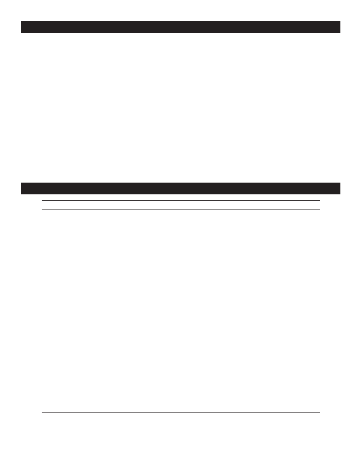
TROUBLESHOOTING
OPERATING ISSUE RECOMMENDATIONS
Staples are not fed properly •Checkthattherighttypeofstaplesarebeingused
•CheckthatthefeederspringisOK
•CheckthatthestaplepusherisOK
•Checkthatthestapletrackiscleanwithnodirtinside
•CheckthatthereturnspringinthestaplingheadisOK
•CheckthatthestaplingheadtripspringsareOKonhead
•CheckthatthesideplatesareOKonhead
Staples are deformed when inserted •Checkthatthestaplingheadbearinghasnoplay
•Checkthattheanvilisproperlycentered
•Checkthatthedriverisnotdamaged
•Checkthatthestaplechannelisclean
Noise level is too high •Checkthattheairpressureisat70psi
•Checkthatthestrokespeedisnotunnecessarilyhigh
The carton is damaged by the stapling head •Checkthattheairpressureisat70psi
•Checkthatthestrokespeedisnotunnecessarilyhigh
The carton is not pressed together properly •Checkthatthelengthofthepistonrodisadjustedproperly
A staple is stuck in the staple head •Removethestaple:
1. Pull the pusher back to take the pressure off the staple strip
2. Loosen the screws that hold the front plate
3. Pull the staple downward to remove
4. Retighten the screws
πCHICAGO•ATLANTA•DALLAS•LOSANGELES•MINNEAPOLIS•NYC/PHILA•SEATTLE•MEXICO•CANADA
1-800-295-5510
uline.com