manuals.online logo
Brands
  1. Home
  2. •
  3. Brands
  4. •
  5. Vimar
  6. •
  7. Control Unit
  8. •
  9. Vimar XT BY-ME PLUS 32002 User manual

Vimar XT BY-ME PLUS 32002 User manual

Viale Vicenza 14
36063 Marostica VI - Italy
www.vimar.com
32002 032306
32002
SMART AUTOMATION BY-ME PLUS
XT electronic control device for By-me home automation system with 100-240
V 50/60 Hz relay output for 500 W incandescent lamps, 100 W LED lamps, 250
VA electronic transformers, 120 W fluorescent lamps, 1 roller shutter operated
by 2 A cosØ 0.6 motor, to be installed on XT mounting frames, to be complet-
ed with By-me XT front modules.
CHARACTERISTICS.
• Rated supply voltage: BUS 29 V derived from the electrified XT mounting frame through spring
contacts.
• Maximum absorption from the BUS: 10 mA (the device does not absorb current from the
power supply node 32001).
• Terminals:
- 2 for L and N (voltage 100-240 V~ 50/60 Hz);
- 2 for the OUT 1 and OUT 2 voltage outputs that control 2 lights or a roller shutter.
• Buttons 1 and 2 for manual relay control.
• LED and OFF push button for configuration/reset.
• Switching on zero crossing.
• Protection degree: IP20.
• Operating temperature: -5 °C ÷ +45°C (indoor use).
• Overall dimensions: 1 module measuring 22.5 mm.
CONTROLLABLE LOADS (20.000 Cycles).
• With the outputs used to control 2 lights:
Max loads for
each output
100 V~ 250 W 50 W 60 W 125 VA
240 V~ 500 W 100 W 120 W 250 VA
• With the outputs used as a single roller shutter output:
Maximum loads Roller shutter motor
100 V~ 2 A cos ø 0.6
240 V~ 2 A cos ø 0.6
N.B. The device is not suitable for controlling relays configured in climate control applica-
tions.
MANUAL MANAGEMENT.
CAUTION: In order to function, the actuator must be installed in the electrified XT mounting
frame together with the related power supply node. The buttons should be pressed once
the device is installed.
The 2 front buttons can always be used for the manual control of the 2 outputs
•If the device has not been configured (in other words the factory values are set) the relays are
controlled by buttons 1 and 2 for the UP () and DOWN () functions respectively; there is
a reversal time in the passage from UP () to DOWN () to protect any motor connected to
the outputs.
•If the device has been configured:
- with the relays configured individually, relay 1 is controlled in toggle mode by button 1 while
relay 2 is controlled by button 2;
-with the relays configured to control the roller shutter, they are controlled by buttons 1 and
2 for the UP () and DOWN () functions with a reversal time in the passage from UP ()
to DOWN ().
CONFIGURATION with View Pro App.
For full details, see the manuals, which can be downloaded from the website www.vimar.
com.
INSTALLATION RULES.
•Installation and configuration must be carried out by qualified persons in compliance with the
current regulations regarding the installation of electrical equipment in the country where the
products are installed.
• The device should be installed on electrified XT mounting frames with:
- 2 modules art. 32602.x (for 2-module mounting box)
- 3 modules art. 32603.x (for 3-module rectangular mounting box)
- 4 modules art. 32604.x and 32614.x (for 4-module rectangular mounting box)
• To install the actuator, slide up the protection flap on the back of the mounting frames.
• The relay output power supply circuit must be protected against overloads by installing a fuse
device with a nominal breaking capacity of 1500 A or automatic 1-way switch type C, with a
rated current not exceeding 10 A.
WEEE - User information
The crossed bin symbol on the appliance or on its packaging indicates that the product at the end of its life must be
collected separately from other waste. The user must therefore hand the equipment at the end of its life cycle over to
the appropriate municipal centres for the differentiated collection of electrical and electronic waste. As an alternative to
independent management, you can deliver the equipment you want to dispose of free of charge to the distributor when
purchasing a new appliance of an equivalent type. You can also deliver electronic products to be disposed of that are
smaller than 25 cm for free, with no obligation to purchase, to electronics distributors with a sales area of at least 400
m2. Proper sorted waste collection for subsequent recycling, processing and environmentally conscious disposal of the
old equipment helps to prevent any possible negative impact on the environment and human health while promoting the
practice of reusing and/or recycling materials used in manufacture.
FRONT AND REAR VIEW
LED and configuration/reset push button
Button 1
Button 2
1
CONF
2
6 mm
N L 1 2
100-240V~ 50/60Hz µ
REGULATORY COMPLIANCE.
LV Directive. EMC directive. RoHS directive.
IEC 60669-2-1, EN 50491-2, EN IEC 63044, EN IEC 63000 standards.
REACH (EU) Regulation no. 1907/2006 – Art.33. The product may contain traces of lead.
Viale Vicenza 14
36063 Marostica VI - Italy
www.vimar.com
32002 032306
CONNECTION TO CONTROL TWO LIGHTS CONNECTION TO CONTROL ONE ROLLER SHUTTER
L
N
6 mm
N L 1 2
100-240V~ 50/60Hz µ
DOWN
UP
INSTALLATION EXAMPLE
L
N
6 mm
N L 1 2
100-240V~ 50/60Hz µ
Observe the direction of installation specified as UP. The hooking and unhooking of the device takes place on the back of the mounting frame regardless of the adjacent connector blocks and
in any position.
MA DE I N ITA LY
32603
VIMAR SPA
VIALE VICENZA 14
36063 MAROSTICA VI
ITALY
6 mm
N L 1 2
100-240V~ 50/60Hz µ
32002
ACTUATOR
UP
MADE IN ITALY
2 x 500W 240V~
2 x 250W 100V~
32001POWER SUPPLY
UP
MADE IN ITALY
+ BU S –
MA DE I N ITA LY
32603
VIMAR SPA
VIALE VICENZA 14
36063 MAROSTICA VI
ITALY
32001POWER SUPPLY
UP
MADE IN ITALY
+ BU S –
6 mm
N L 1 2
100-240V~ 50/60Hz µ
32002
ACTUATOR
UP
MADE IN ITALY
2 x 500W 240V~
2 x 250W 100V~
UP
UP
XT
UP
REMOVING THE DEVICEHOOKING THE DEVICE
MA DE I N ITA LY
32603
VIMAR SPA
VIALE VICENZA 14
36063 MAROSTICA VI
ITALY
32001POWER SUPPLY
UP
MADE IN ITALY
+ BUS –
6 mm
N L 1 2
100-240V~ 50/60Hz µ
32002
ACTUATOR
UP
MADE IN ITALY
2 x 500W 240V~
2 x 250W 100V~
32002
UP
32002
UP
32002
UP
Click
1 2 3
MA DE I N ITA LY
32603
VIMAR SPA
VIALE VICENZA 14
36063 MAROSTICA VI
ITA LY
32001POWER SUPPLY
UP
MADE IN ITALY
+ BU S –
6 mm
N L 1 2
100-240V~ 50/60Hz µ
32002
ACTUATOR
UP
MADE IN ITALY
2 x 500W 240V~
2 x 250W 100V~
32002
UP
1
2

Other Vimar Control Unit manuals

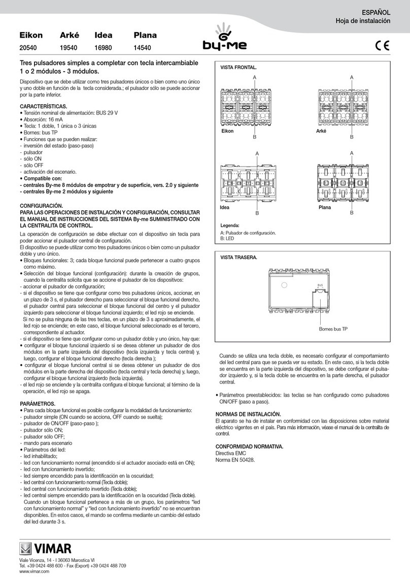
Vimar 6153/682 Assembly instructions

Vimar

Vimar 6153/682 Assembly instructions

Vimar 21125 User guide

Vimar

Vimar 21125 User guide

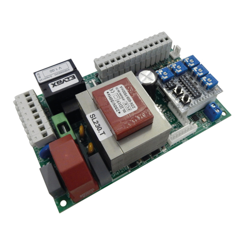
Vimar ELVOX SL230.T User manual

Vimar

Vimar ELVOX SL230.T User manual

Vimar ELVOX EMC.W User manual

Vimar

Vimar ELVOX EMC.W User manual

Vimar by-me Eikon 20527.1 User manual

Vimar

Vimar by-me Eikon 20527.1 User manual

Vimar SL24.W User manual

Vimar

Vimar SL24.W User manual

Vimar by-me Eikon 20540 User manual

Vimar

Vimar by-me Eikon 20540 User manual

Vimar NEVE UP 09591.0 User manual

Vimar

Vimar NEVE UP 09591.0 User manual

Vimar Eikon User manual

Vimar

Vimar Eikon User manual

Vimar by-me Eikon TACTIL User manual

Vimar

Vimar by-me Eikon TACTIL User manual

Vimar 03981 User manual

Vimar

Vimar 03981 User manual

Vimar ELVOX SW24.W User manual

Vimar

Vimar ELVOX SW24.W User manual

Vimar LINEA 30506 User manual

Vimar

Vimar LINEA 30506 User manual

Vimar Elvox 8051/0 Assembly instructions

Vimar

Vimar Elvox 8051/0 Assembly instructions

Vimar Eikon User manual

Vimar

Vimar Eikon User manual

Vimar Elvox ECP2 User manual

Vimar

Vimar Elvox ECP2 User manual

Vimar BY-ALARM PLUS 0K03800 User manual

Vimar

Vimar BY-ALARM PLUS 0K03800 User manual

Vimar Elvox 12TS User manual

Vimar

Vimar Elvox 12TS User manual

Vimar by-me Eikon 20520 User manual

Vimar

Vimar by-me Eikon 20520 User manual

Vimar ELVOX ECP1 User manual

Vimar

Vimar ELVOX ECP1 User manual

Vimar ELVOX ECG1 User manual

Vimar

Vimar ELVOX ECG1 User manual

Vimar ELVOX 69DV Assembly instructions

Vimar

Vimar ELVOX 69DV Assembly instructions

Vimar Elvox ECGF User manual

Vimar

Vimar Elvox ECGF User manual

Vimar 00801 User manual

Vimar

Vimar 00801 User manual

Popular Control Unit manuals by other brands

Feig Electronic cVEND plug Installation

Feig Electronic

Feig Electronic cVEND plug Installation

Ross W74 Series quick start guide

Ross

Ross W74 Series quick start guide

Phasemation CM-1000 owner's manual

Phasemation

Phasemation CM-1000 owner's manual

Extron electronics IRCM-DVplus Setup guide

Extron electronics

Extron electronics IRCM-DVplus Setup guide

National Instruments sbRIO-9205 Getting started guide

National Instruments

National Instruments sbRIO-9205 Getting started guide

Doyson S 400 user manual

Doyson

Doyson S 400 user manual

Kinova Gripper adapter  KR11703-01 installation guide

Kinova

Kinova Gripper adapter KR11703-01 installation guide

DeZurik APCO AVV-140 instructions

DeZurik

DeZurik APCO AVV-140 instructions

Oasis SV104 instruction manual

Oasis

Oasis SV104 instruction manual

Danfoss SVA-S 6-10 installation guide

Danfoss

Danfoss SVA-S 6-10 installation guide

Burkert 0283 operating instructions

Burkert

Burkert 0283 operating instructions

Emerson QC54 FOUNDATION installation guide

Emerson

Emerson QC54 FOUNDATION installation guide

Ariston NIMBUS HYBRID MODULE NET user manual

Ariston

Ariston NIMBUS HYBRID MODULE NET user manual

Kahlenberg M-511C instruction sheet

Kahlenberg

Kahlenberg M-511C instruction sheet

Edyn ED01-001 user manual

Edyn

Edyn ED01-001 user manual

Advantech EPD-132 user manual

Advantech

Advantech EPD-132 user manual

Mitsubishi Electric AJ65BT-68TD user manual

Mitsubishi Electric

Mitsubishi Electric AJ65BT-68TD user manual

Zte mg3732 user manual

Zte

Zte mg3732 user manual

manuals.online logo
manuals.online logoBrands
  • About & Mission
  • Contact us
  • Privacy Policy
  • Terms and Conditions

Copyright 2025 Manuals.Online. All Rights Reserved.