WolfVision VZ-27plus User manual

R
Check out our Internet Homepage for additional information
ENGLISH / DEUTSCH
www.wolfvision.com/support
INSTRUCTIONS
BEDIENUNGSANLEITUNG
INSTRUCTIONS
VZ-27plus / VZ-57plus
BEDIENUNGSANLEITUNG

Printed in Austria, September 2005 Design and specifications subject to change!
USE THIS MACHINE ONLY WITH THE CORRECT VOLTAGE AS SHOWN ON THE TYPE LABEL !
DO NOT EXPOSE THE UNIT TO EXTREME HEAT OR MOISTURE !
DO NOT CARRY THE VISUALIZER HOLDING IT ONLY BY ITS MIRROR ARM (#1) !
PROTECT THE UNIT FROM EXCESSIVE SHOCKS !
Make sure that sufficient air circulation for cooling the unit is possible (ventilation slots on the left and
right side of the unit)!
If there is any abnormality (abnormal noise, smell, smoke etc.) disconnect the unit from mains immediately
and contact your Visualizer dealer!
Do not use a damaged power cord.
This may cause short circuits or electrical shocks!
Do not modify the Visualizer or operate it without the cover panel firmly in place, to prevent danger!
Do not expose the Visualizer to water, metallic objects or any flammable material.
Avoid installing the Visualizer in environments where there is radiation.
Avoid installing the Visualizer in locations exposed to strong magnetic fields or electrical currents. This
could cause monitor image distortion or damage to the CCD camera.
If the Visualizer is not used for a long time, disconnect it from mains!
Precautions
LASER RADIATION
DO NOT STARE INTO BEAM
CLASS 2 LASER PRODUCT
OUTPUT POWER <1mW
WAVELENGTH 650nm
EN 60825-1 March 1997
AVOID EXPOSURE -
Laser radiation is emitted
from this aperture. FDA accession
number:
9912688-00
This device
complies with
21 CFR 1040.10
and 1040.11
LASER RADIATION - DO NOT
STARE INTO BEAM
650nm, P<1mW
CLASS II LASER PRODUCT
1
ENGLISH
Risk of electric shock
Dangerous voltage inside
WARNING!
Please follow these precautions:
Precautions for built-in laser pointer:
The professional WolfVision Visualizer system was developed and designed by WolfVision in Austria.
Patents (examples): US 5027219, FRG 3833908, CH 678576.
This equipment has been tested and found to comply with the limits for a Class B digital device, pursuant to Part
15 of the FCC Rules. These limits are designed to provide reasonable protection against harmful interference when
the equipment is operated in a commercial environment. This equipment generates, uses, and can radiate radio
frequency energy and, if not installed and used in accordance with the instruction manual, may cause harmful
interference to radio communications. Operation of this equipment in a residential area is likely to cause harmful
interference in which case the user will be required to correct the interference at his own expense.
This product is built according to Directive EMC and to Directive electrical equipment.
Inspections, tests and evaluation according to UL 60950. CSA22.22-60950
Inspections, tests and evaluation according the CB-Scheme

CONTROL PANEL:
1
2
3
6
7
8
9
10
4
11 5
REMOTE
CONTROL:
#12 Upper MIRROR up and down (for scrolling)
(Can also be moved by hand! This does not
cause any harm to the motor of this mirror!)
#13 ZOOM keys
#14 Three user programmable PRESETS
(see page 7)
#15 IMAGE TURN key (see page 6)
#16 TEXT Enhancement key improves the
contrast for better readability (see page 7)
#17 FREEZE key to freeze the current image
(see page 7)
#18 MACRO
For bigger enlargements (see page 5)
#19 Manual FOCUS adjustment (see page 5)
#20 EXT / INT switches between Visualizer
image and external input (see page 8)
#21 LIGHT switches between "Top light",
"Bottom light" and "Light off"
#22 WHITE activates one push
WHITE BALANCE adjustment (see page 7)
#23 MENU activates the on-screen menu
(see page 9)
#24 Manual IRIS makes image brighter or darker
(see page 5)
#25 HELP activates the on-screen help for the
on-screen menu. This key is only available
after pressing the MENU key (#23) for 1 sec.
#26 SELECT keys for on-screen menu (only
available after pressing the MENU key (#23)
for 1 sec.)
#27 Motorized ARM up and down
#28 (Standby) POWER on and off
#29 Power indication LED (red=off, green=on)
Only on remote control:
#30 ALL-key for displaying all 9 pictures of the
memory as split image (see page 8)
#31 MEMORY keys 1-9 (see page 8)
#32 LASER pointer key
Important: Do not stare directly into the beam.
This would be bad for your eyes!
2
#1 Arm
#2 Base mirror
#3 Top mirror (sensing head)
#4 Control panel
#5 Synchronized lightfield (top light)
#6 Remote Control
#7 Ventilation, air outlet
#8 Ventilation, air inlet
#9 Working surface with built-in
Bottom light (removable)
#10 Connectors on the back
(see page 11, 12)
#11 Lamp exchange cover
under the removable bottom light
(see page 10)
MENU POWER
ZOOM MIRROR
LASER
EXT / INT ALLTEXT
FOCUS IRIS
12 3
A
A
AF
MEMORY
123
456
789
HELP
PRESETS IMAGE TURN
LIGHT
A
A
FREEZE
EXT/INT
WHITE
AF

BASIC PREPARATIONS
1. Connect the power cable to the unit (#35) and plug it in.
2. If you would like to use a control monitor, connect it to the following outputs:
Computer monitors: Preview RGB output (#39)
Video monitors: Y/C (S-Video) output (#43) or Composite Video output (#44).
3. Connect a large viewing monitor or a projector to one of the outputs of the Visualizer.
For choosing the right output please read page 11 and 12!
4. Turn the main power switch (#33, on the back of the unit) to "I". The red power indicator
(#29) on the control panel indicates that power is supplied.
5. If the arm is folded down press the ARM-key (#27) on the control panel, then the arm
comes up automatically.
6. Press the POWER-key (#28) on the control panel.
The Visualizer now runs the "power-on preset" (=automatic focusing of anA5 format on
the working surface) during which the green LED light (#29) is flashing. As soon as
the green LED light stays illuminated you can start working with the Visualizer.
(The behaviour of the unit once that power is supplied to the unit or after the POWER-
key is pressed can be changed in the unit's menu - see page 9 and on-screen help)
3
HOW THE VISUALIZER WORKS
a
e
c
b
f
g
d
a) light projector
b) camera
c) light path
d) image path
e) base mirror
f) top mirror
g) pickup area /
synchronized
lightfield
A light projector (a) inside the unit projects a
lightfield (g) the same size as the pick-up
area of the built-in camera via the base mirror
(e) and the top mirror (f) onto the working
surface. The image is recorded by the camera
(b) using the same path.
The lenses of the light projector (a) and the
camera (b) are synchronized. Thus the size of
the light field on the working surface changes
when the user changes the zoom range of the
camera.
This scanning and illumination system is a
worldwide patent from WolfVision.

WORKING ON THE WORKING SURFACE
Synchronized
lightfield
1. Place your subject material on the working surface.
A synchronized lightfield on the working surface marks the pick-up area
of the built-in camera! Just place your subject material in the illuminated
area.
2. Select the enlargement required with the ZOOM-keys (#13).
3. Use the MIRROR-keys (#12) on the control panel or the remote control to
change the vertical position of the pick-up area. The upper mirror can also
be moved by hand! This does not cause any harm to the motor of this
mirror!
DO NOT TOUCH THE MIRROR SURFACE, AS FINGERPRINTS
CAUSE BRIGHT AND HAZY SPOTS ON THE PICTURE ! ALWAYS
KEEP THE MIRROR CLEAN ! - see page 13
CAUTION: SENSITIVE FRONT COATED MIRROR!
SYNCHRONIZED LIGHTFIELD
If the top light of the Visualizer is used (normal working condition) a synchronized lightfield
always marks the pick-up area of the built-in camera on the working surface.
The alignment of this lightfield is made for working on the working surface. Because of the oblique
mounting of the camera and the light projector of the Visualizer the lightfield shifts to the left when the
distance between the Visualizer and the scanned object is increased (when capturing images outside
of the working surface). This means that the lightfield no longer exactly shows the recorded area. In this
case switch off the Visualizer’s top light with the LIGHT-key (#21) and work with room light.
4
WORKING OUTSIDE THE WORKING SURFACE
700mm (27.6")
to infinity
For showing 3-dimensional objects with the WolfVision Visualizer, just place them on the working
surface and adjust ZOOM and FOCUS (as mentioned). Due to a special WolfVision lens the object can
be up to 25 cm (9.7") in height. If the object is to big for the working surface or if you want to show it
from the side just place it behind or in front of the unit and tilt the top mirror by hand or using the
MIRROR-keys (#12).
In this way it is also possible to make
recordings of objects in the room or
surrounding area, just like with a video
camera.
Due to the great focal range it is possible to
show details in every distance to the unit.
If you want to record people you should turn
off the light with the LIGHT-key (#21), so that
they are not blinded by the light.

FOCUSING +
When the Visualizer is turned on the focus automatically adjusts to the working
surface level. As a result it is not necessary to readjust the focus if you are only working with flat
material (text, photos etc.). Furthermore, due to the great depth of focus of the Visualizer it is rarely
necessary to readjust the focus.
Only very high objects require a focus adjustment.
Pressing both FOCUS-keys (#19) simultaneously, activates a One-Push Auto focus.
(Please note that this is a new function, introduced in Mai 2005 with firmware Version 1.13a.
Units with older firmware perform an Auto focus for flat objects with this key combination.)
AUTO IRIS / MANUAL IRIS
WolfVision Visualizers are equipped with auto-iris. That means that the brightness of
the camera image adjusts automatically. Using the IRIS-keys (#24) the auto iris function is switched off.
In this mode the Iris can be adjusted manually.
When using the ZOOM-keys (#13) the auto iris function is switched on again. Before the iris closes
completely, the Visualizer automatically dims the light.
The standard auto iris level can be set brighter or darker in the unit's menu
- see page 9 and on-screen help.
5
MACRO MODE / 4x DIGITAL ZOOM
In the fully extended position of the arm, the smallest pick-up
area is 42 x 33mm (1.6" x 1.3").
When pressing the MACRO-key (#18) the length of the arm is
automatically reduced, this allows greater enlargements. In the
macro mode the smallest pick-up area with full optical
resolution is: 30 x 22mm (1.2" x 0.9"). When zooming in, the
zoom stops at this size.
Laser
center
marker
Plea ee:
s not
Itisv im antth nos ray
ery port at t
ligh shine ot ec n,
t sont h sree
ast ism ayin te t evideoh erfer h
projtionp tue.ec ic r
Fu her or it sals importantrtm e i o
t atth au ienc or hes e erh edet p ak
on get b edb a brigh ligt
d ot lindy t h
a ark omind ro.
Pleasenote:
Itis very important that no stray
h
lightshines onto t e screen,
asthis may interfere the video
projectionpicture.
Furthermoreit is also important
e
thatth audience or the speaker
oid notget blinded by a brightl ght
ina dark room.
If you press the ZOOM IN-key again after the stop, the unit activates its digital zoom extension. In this
mode you can zoom into a picture as small as 8 x 6mm (0.3" x 0.2”).
Please note that the resolution in the digital zoom area is lower!
The MACRO-key is illuminated in red color if the macro function is activated.
Please note that the macro mode has the following limitations:
- The depth of focus and the object height that can be focused is not as large as in the fully
extended arm position.
- The largest pick-up size is only about 42 x 33 mm (1.6" x 1.3").
- When zooming the Synchronized Lightfield stays at a larger size and no longer marks the pick-up
area of the built-in camera. The Laser Center Marker (see next chapter) is activated as a substitute.
If sufficient depth of focus and focusing high objects in the macro mode is more important than big
enlargements, it is possible to switch the Visualizer from 12x zoom to 11x zoom in the Visualizer's
menu (see page 9). The smallest pick-up size in the 11x macro mode is only 33 x 25mm (1.3" x 1"), but
the depth of focus is larger than in the 12x macro mode.

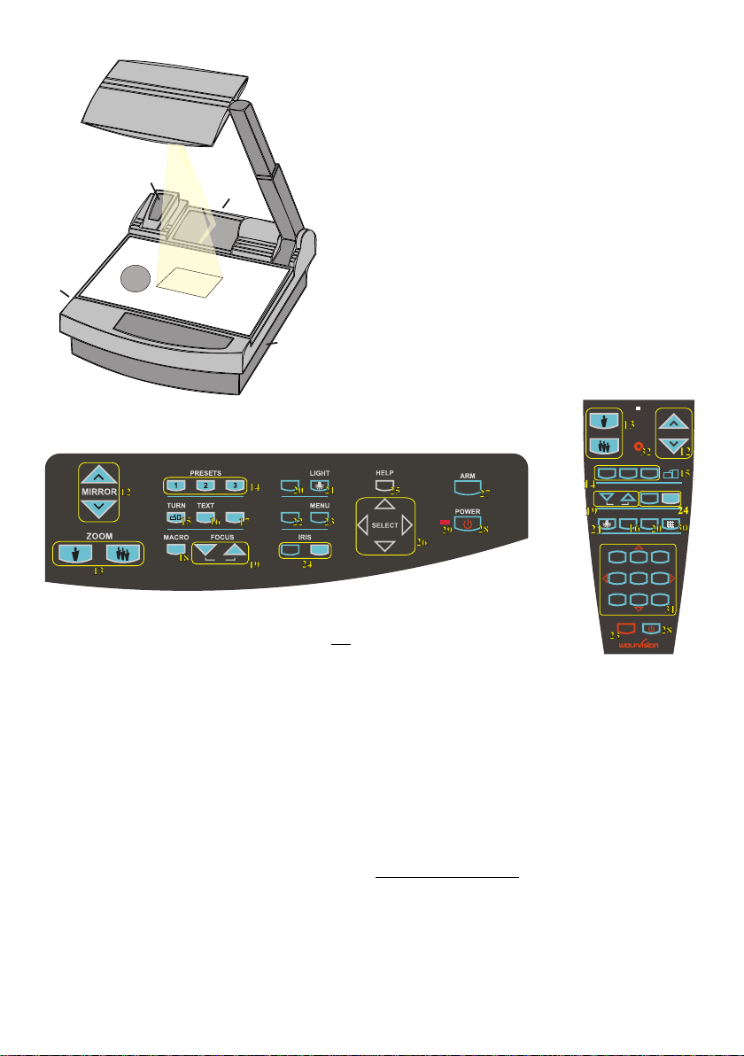
BOTTOM LIGHT / LASER CENTER MARKER
Laser
center
marker
The LIGHT-key (#21) can be used to switch between:
"Top light" (with Synchronized Lightfield)
"Bottom light" with Laser Center Marker
"Light off"
The bottom light should be used for dark transparent materials such as x-
rays or for very small transparent material such as slides.
Using the bottom light has the disadvantage that the Synchronized Lightfield
of the top light no longer marks the pick-up area of the built-in camera.
However as a substitute the Visualizer has a built-in Laser Center Marker,
which marks the center of the pick-up area. This can also be used for
positioning of objects (especially with big enlargements, like when picking
up a slide).
The Laser Center Marker is only visible on the working surface and NOT on the picture the audience
sees. For safety reasons the Laser Center Marker is automatically switched off when the top mirror is
tilted to record outside of the working surface. If required the Laser Center Marker can also be switched
off completely in the unit's menu (see page 9 and on-screen help menu).
Please note that for technical (optical) reasons the laser center marker can not show the exact middle
center of the pickup area in every position of the arm. This is not a failure of the unit! However it is
always very close to the center.
6
WORKING WITH TRANSPARENCIES
Pleasenote:
Itisveryimportantthatnostray
lightshinesontothescreen,
asthismayinterferethe video
projectionpicture.
Furthermoreitisalsoimportant
thattheaudienceor the speaker
donotgetblinded by a bright light
inadarkroom.
The working surface of the Visualizer (#9) has a special crystalline white color,
which is especially designed for perfect reproduction of transparencies.
Even though the professional Visualizers have a built-in bottom light it is
recommended to use the top light for transparencies, because of the better
color reproduction and the advantage that the Synchronized Lightfield still
shows the pickup-area of the built-in camera.
However in these situations it is recommended to use the bottom light:
- If the transparency is very dark
- If the transparency is very wavy and causes reflections
- If the room light causes reflections on a transparency
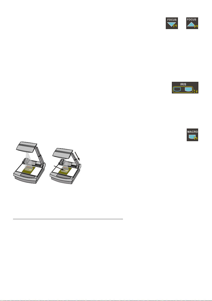
IMAGE TURN MODE (for higher resolution)
Picking up a complete vertical (portrait) document or
A4 page has always been a critical issue for a
Visualizer, because the image is always picked up in
a horizontal (landscape) format.
The camera could only use 50% of its pixels to pick
up a vertical (portrait) page. WolfVision's Image turn
mode solves this problem.
Just place your document (or other vertical object)
º
on the working surface horizontally and zoom in on it
completely, so that about 90% of the pixels of the built-in camera are used to pick up the document.
Then press the IMAGE TURN-key (#15) one time. The Visualizer turns the picture electronically 90
and outputs it the right way up with a much higher resolution than in normal mode. The left and right
margins are black.
The IMAGE TURN-key (#15) can also be used to rotate the image 90, 180 and 270 degrees.
Each time this key is pressed, the image rotates 90 degrees.
A
A
AA
Working surface: Output picture:
Normal mode:
Image turn mode:
Only 50% of the
pixels are used to
pick up the document
90% of the pixels
are used to pick
up the document

WolfVision Visualizers offer the possibility of programming three presets for the functions: Zoom,
Focus, Iris, Light, Text, Macro, White Balance, Mirror position*, Positive/Negative and Black/White.
They can be recalled by pressing one of the three PRESET-keys (#14) on the control panel or the
remote control.
This function is very useful for example if a user requires one preset for papers on the working surface,
one for working with slides (bottom light) and one for an object placed in front of the unit. During his
presentation the user just has to press one of the PRESET-keys when he changes from one object to
.
PRESET FUNCTION
Quickly pressing: Recalling a preset
More than 2 seconds: Saving a new preset * You can select in the unit's on-screen menu if
the mirror position should be stored in a
preset or not (see page 9). Default is: YES.
WHITE BALANCE ADJUSTMENT IMPORTANT
Each time the lighting condition changes, the user should adjust the white balance of the Visualizer's
camera, in order to optimize the color reproduction. The Visualizer's top- and bottom-light have the
same color temperature so normally a new white balance adjustment is not necessary when changing
from one light to the other, but if there is also room light or sun light shining on the working surface,
the white balance should be adjusted.
Top light: First, zoom in on a white object (for example a white paper) until there is only white on the
screen. Then press the WHITE-key (#22).
Bottom light: Turn on the bottom light with the LIGHT-key (#21). Remove everything from the working
surface. Zoom to the smallest picture. Then press the WHITE-key (#22).
You can adjust the white balance either for the top or for the bottom light and it works well with both
lights. When the white balance adjustment is finished successfully the message "WHITE OK" appears
on the monitor after a few seconds. The new white balance is stored automatically and is preserved
even if the power supply is interrupted.
7
WHITE
TEXT ENHANCEMENT IMPORTANT
For improving the readability of text, sketches and x-rays press the TEXT-key (#16). This mode
enhances the contrast of the picture. Please note that in this mode the colors are darker than usual. To
switch off the text enhancement mode press the TEXT-key again.
While the text mode is activated the TEXT-key on the control panel is illuminated red.
FREEZE
The current image can be frozen by pressing the FREEZE-key 7 .
The FREEZE-key is red illuminated if the freeze function is activated. The FREEZE-key also works as
image memory key if pressed for 2 seconds (see page 8).
The behavior of the FREEZE-key can be changed in the on-screen menu (see page 9).
(#1 )
FREEZE
For programming a preset just adjust every function as required and then keep one of the PRESET
keys pressed for more than 2 seconds. The on-screen menu tells you when the preset is stored.
When the presets are stored as mentioned above, all current settings like zoom-, focus- or mirror-
position are stored. Contrary to this, a user also has the opportunity to assign only specific functions
such as "Freeze", "Iris open/close", "Negative", "Negative/Blue", "Black/White" etc. to a PRESET-key.
This can be done in the on-screen menu of the Visualizer (see page 9).

9-IMAGE MEMORY
Split image of 9 picture memory
When pressing the ALL-key (#30) for 4 seconds, a menu appears on the screen asking if you would
like to erase all stored pictures (black picture) or if you would like to fill the memory with “snapshots”.
When choosing “snapshot” the Visualizer stores a new image every second until the 9 memory
locations are full.
The Visualizer is equipped with a memory backup battery. It stores the pictures in the memory when the
power supply is disconnected for up to 4 weeks. Images can also be stored by pressing the FREEZE-
key (#17) for 2 seconds. The image will be stored in the next available memory (1-9). If the memory is
full, an on-screen message will appear.
The functional settings of the memory feature can be changed in the on-screen menu (see page 9).
You can store 9 images and recall them by just pressing one of the
numerical keys (#31) on the infrared remote control:
Storing an image: Press one of the MEMORY-keys (#31)
for more than 2 seconds
Recalling an image: Press one of the MEMORY-keys (#31)
quickly
By pressing the ALL-key (#30) a split image with all 9 pictures of the
memory can be displayed.
8
The LAN connection (10BASE-T/100BASE-TX) can be used for controlling the Visualizer over a
computer network, image transfers and firmware updates.
The following protocols are supported: TCP/IP, ICMP and ARP.
:Supported Browsers are Internet Explorer, Netscape Navigator and Mozilla.
Standard settings (changeable): IP-address and Subnet-mask from DHCP-Server
Image Transfer Resolution: Still Image: 1024x768 (or 512x384), Live Image: 160x120
Please check the special ETHERNET/LAN manual on our homepage at:
www.wolfvision.com/support.
ETHERNET / LAN
A Computer can be connected to the External RGB input (#41) of the Visualizer.
By pressing the EXT/INT-key (#20), you can switch between the Visualizer image and the image of the
external input to displayed to the audience.
The extern mode can also be used for only one output. The behavior can be changed in the on-screen
menu (see page 9). The Visualizer has a built-in scaler (A/D-converter) in order to digitize the analog
RGB signal from the computer and output it on all outputs in the selected format (allowed signals: from
VGA to SXGA/75Hz). As the built-in scaler allows the image from the external input to be output on the
PAL/NTSC video outputs, the Visualizer can also be used as a computer to video image converter.
EXTERNAL INPUT / SCALER EXT/INT
USB-PORT
CERTIFIED
HI-SPEED
TM
The USB 2.0 port of the Visualizer can be used to capture and
transfer Visualizer images onto a computer.
In this way the Visualizer can be used as a scanner for
3-dimensional objects for your computer. Just connect the USB
port (#37) of the Visualizer to the USB port of your computer, using
the supplied USB cable. The software is fully Twain compatible.
The USB 2.0 output of the Visualizer is fully USB 1.1 compatible
(less speed with USB 1.1).
The WolfVision USB-software can be found on the supplied CD-ROM. Please check our Internet
homepage at: www.wolfvision.com/support if an update of this software is available as a free-
download. The software works under Windows 98/ME/2000/XP and MAC OS10 (or later).
Windows 95 and NT will not work, because they do not support USB.

For standard use of the WolfVision Visualizer it is not necessary to enter the on-screen menu
of the Visualizer and change settings. Inexperienced users should not make any adjustments here.
To enter the on-screen menu press the MENU-key (#23) for one second. Settings of the Visualizer's
basic functions and the built-in camera can be made here using the 4 select keys (#26, = the numerical
keys with red arrows on the remote control - #31).
Please note that some basic settings in the menu can only be changed if you set the menu item
"Format protect" to "OFF" first.
If more information on a function in the on-screen menu is required just set the cursor in the respective
line and press the HELP key (#25, or the Number 5 key #31, this key has a double function). A detailed
description of this function appears on the screen. If you want to reset the selected item to the default
setting, just press the HELP key (#25, or Number 5 key #31) for 2 seconds!
The functions of the on-screen menu are not described in detail in this user manual as the help menu is
an integrated part of the Visualizer's software (firmware). The information you see on your screen
always belongs to the current Visualizer firmware.
ON-SCREEN MENU / ON-SCREEN HELP
SWITCHING to NEGATIVE, NEGATIVE/BLUE and BLACK/WHITE
The output image of the Visualizers can be switched from positive to negative in the on-screen menu.
In addition, the background of a negative image can be switched to blue for better readability of text.
You can also switch between color and black/white in the on-screen menu.
TIP: If you often switch to negative, negative/blue or black/white images you can assign this function to
one of the PRESET-keys (#14) in the on-screen menu (see page 7).
AUTO POWER OFF
In the "Power control" settings in the on-screen menu you can select that the Visualizer will be
automatically switched off, if not used for a certain amount of time.
CHANGING THE STANDARD CONTRAST (color) SETTINGS
If the picture or the colors on your screen appear to be too dark, you can lower the overall contrast of
the picture in the "Color settings" menu of the on-screen menu. The settings can be made separately
for the normal mode and the text-mode.
RESET of ON-SCREEN MENU SETTINGS
All settings in the on-screen menu can be set back to the factory defaults. "Reset" is one item in the on-
screen menu. In case you can not read the menu on a screen you can also set the unit back to the
factory defaults by simultaneously pressing the EXT/INT-keys (#20) and the MENU-key (#23) on the
unit.
If you only want to reset a currently selected item to the default setting, press the Help-key (#25, or
Number 5-key on the remote control #31) for 2 seconds!
FIRMWARE UPGRADES
The software (firmware) of your Visualizer (including the o ) can easily be upgraded to
the latest version.
First download the latest firmware and WolfVision's firmware update utility program from Wolfvision's
internet homepage at www.wolfvision.com/support.
Then connect the Visualizer to your computer and run the firmware update utility program. More details
on the firmware updates can be found on WolfVision's internet homepage.
n-screen HELP
The firmware update can be done via USB, Ethernet (LAN) or RS232.
9

Please note that an infrared remote control can only be used up to a certain distance from the unit.
Objects situated between the Visualizer and the infrared remote control, and weak batteries, interfere
with the reception. If the Visualizer can only be controlled from a close distance, or if it cannot be
controlled at all with the infrared remote control, you may have to change the batteries. Open the cover
on the back of the remote control by hand and replace the two 1.5 V AA batteries with new ones.
Check the polarity of the batteries!
on-
screen menu, by pressing the menu-key (#23) for one second, go
to
(#14)
(#13) - each time this key combination is used, the code switches from A
to B, C, D ... A ...etc. For resetting the remote control to code A
simultaneously p .
The LED shows the selected code (it flashes one-time for code A,
two-times for code B, three-times for code C and four-times for code D)
If a user wants to work with a number of WolfVision Visualizers
simultaneously, each unit can be set to a different infrared code,
so up to 4 units can be controlled individually with their remote controls.
To change the infrared codes on the Visualizer, enter the
"Misc. Settings" and set the "IR Code" to A, B, C or D (code A is
default). To change the infrared code on the remote control,
simultaneously press PRESET 1, PRESET 2 and ZOOM TELE
ress PRESET 1, PRESET 2 and ZOOM WIDE
10
INFRARED REMOTE CONTROL
front back (open)
-
+
-
+
XX
MENU POWER
ZOOM MIRROR
LASER
EXT / INT ALLTEXT
FOCUS IRIS
12 3
A
A
AF
MEMORY
123
456
789
HELP
PRESETS IMAGE TURN
LIGHT
AUTOMATIC LAMP CHANGER
The Visualizer is fitted with an automatic lamp changer. If one lamp fails, there is no need
to replace it immediately, as the automatic lamp changer automatically switches to the second (spare)
lamp. When the unit changes lamps there is an on-screen message saying: "Changing lamp".
When switching on the unit the Visualizer checks if both lamps are working. If one lamp fails there will
be an on screen message for a couple of seconds displaying "Lamp x blown". This prevents a user
from forgetting to change a defective lamp.
If a lamp is not fully defective but worn out and as a result the light output is quite weak, you can switch
manually to the second lamp by pressing the LIGHT-key (#21) for 2 seconds.
THERMOSTAT
If the unit gets too hot (improper ventilation or air extraction) a built in thermostat will switch off the light
of the Visualizer. Verify that proper ventilation and air extraction is available and allow the unit to cool.
EXCHANGING LAMPS
1. Turn the unit off (#28) and disconnect the
power cord!
2. Remove the bottom light (#9) by pulling the
two spring catches (situated left and right of
the control panel) to the front and lift up the
bottom light plate.
3. Remove the lamp exchange cover (#11)
by turning anti-clockwise and lift it.
4. Change the lamp (or both lamps)
Before changing the lamp allow it to cool or use a cloth to avoid burning a finger! When pressing a new
lamp into the socket use a cloth to prevent fingerprints on the lamp!
Only use 12 V/100 W halogen lamps (socket: GY 6,35), type: Osram HLX 64623,
Ansi EVA, LIF M/28 NAED 54052. These are relatively inexpensive standard OHP lamps.
Lamp exchange
cover (#11)

#33 Main POWER switch
#34 FUSE (see page 13)
#35 POWER connection
#36 DVI output (see below and page 13)
#37 USB port (see page 8)
#38 RS-232 port for external remote
controlling (see page 13)
CONNECTORS
#39 PREVIEW RGB output for control monitor
#40 RGB output 15-pin (see below)
#41 EXTERNAL Input for Computers (see page 8)
#42 RGB output BNC connectors (see below)
#43 PAL/NTSC S-Video (Y/C) output (see page 12)
#44 PAL/NTSC Composite video output (see page 12)
#45 LAN 10/100 TBASE (see page 8)
33
35
34
The RGB-, Preview- and DVI-outputs can output a signal in the following formats:
- VGA / 60 (4:3 - 640x480 Pixel) at 60Hz
- SVGA (4:3 - 800x600 Pixel) at 60Hz, 75Hz or 85Hz
- XGA (4:3 - 1024x768 Pixel) at 60Hz, 75Hz or 85Hz - native image
- SXGA- (4:3 - 1280x960) at 60Hz or 85Hz
- SXGA (4:3 - 1280x1024 Pixel) at 60Hz, 75Hz or 85Hz
- SXGA+ (4:3 - 1360x1024) at 60Hz or 75Hz
- UXGA (4:3 - 1600x1200 Pixel) at 60Hz
- XGA 16:9 at 60Hz (special format for not HDTV-capable 16:9-Plasma displays)
- WXGA/60 (16:9 Widescreen - 1366x768 Pixel at 60Hz)
- WSXGA+/60 (16:10 Widescreen - 1680x1050 Pixel at 60Hz)
- 720p/50 (16:9 Widescreen HD/HDTV - 1280x720 Pixel at 50Hz)
- 720p/60 (16:9 Widescreen HD/HDTV - 1280x720 Pixel at 60Hz)
- 1080p/50 (16:9 Widescreen HD/HDTV - 1920x1080 Pixel at 50Hz)
- 1080p/60 (16:9 Widescreen HD/HDTV - 1920x1080 Pixel at 60Hz)
The "Auto Resolution" function is activated by default. In this mode the Visualizer constantly checks
which devices are connected to RGB (#39, 40) and DVI output (#36) and automatically sets the optimal
output mode for each connected device separately.
Please note that the Visualizer can not check the possible resolution, if the connected units or the
cables* are not "Plug and Play" compatible. If the Visualizer can not detect the resolution of the
connected device, the output is set to the default of XGA (1024x768)/60Hz.
(* Cables with plug and play compatibility must have a 15-pin plug on both ends with all pins connected, pin 9 is not used)
If you can not use the “Auto Resolution” function, you can select the output mode manually in the on-
screen menu of the Visualizer. Resolution and refresh rate can be adjusted separately for the outputs.
In order to achieve the best picture quality you must set the outputs of the Visualizer to match the native
resolution of your display unit (e.g. LCD or DLP projector or monitor).
Important: What matters is the native resolution of the projector or monitor, not the maximum resolution
that it can display (in compressed mode). The native resolution is the actual number of pixels of the built
in LCD display or DLP chip of a projector or monitor. Most LCD or DLP projectors can also display higher
resolutions than their native resolution, but only in compressed mode and with inferior picture quality. Do
NOT set the output of the Visualizer to a higher standard than the native resolution of your
display unit!
If you output the Visualizer image on a CRT-monitor or CRT-projector, use an output mode with 75Hz or
85Hz, because 60Hz may show a slight image flickering. For LCD/DLP-projectors or -monitors and video
conferencing units 60Hz is the best choice. If you are unsure what is the best mode, check the user
manual of the connected units.
Do not set a higher refresh rate than your monitor or projector can display, otherwise the monitor
or projector can be damaged! Follow the instructions in the user manual of the connected units!
Choosing the right output mode
11
FUSE
T3,15A
RGB 40
PREVIEW
EXTERN IN 39
41
R G B 42
DVI USB
38 S-VIDEO
Video
36 37
43
44
LAN 45
RS-232
VH

PAL / NTSC VIDEO OUTPUTS
The Y/C (S-video) (#43) and Composite (#44) video outputs can be switched between PAL and NTSC
in the units . e FREEZE-17
14 unit
he picture quality of both video outputs is BY FAR NOT AS
GOOD as the picture quality of the data outputs
on-screen menu Switching can also be done by pressing th key (# ) together
with the Preset 1 (for PAL) or Preset 2 (for NTSC) (# ) key on the .
Please note, that the picture quality of the Y/C (S-video) (#43) output is BETTER than the quality of the
Composite (#44) video output. However t (#39, 40, 42 and 36). This is because of the
limitations of the PAL/NTSC video system and because of the fact that this is just a converted
Progressive Scan signal and not an original video signal.
12
Widescreen is supported since Firmware Version 1.20a (Older units may need a Firmware
update for Widescreen support).
Please note that WolfVision added widescreen support to the Visualizers in order to assure
100% compatibility with all display units on the market. However the native image ratio of
the Visualizer camera is 4:3. Therefore 25% of the picture (4:3) is cut off when the
Visualizer outputs in 16:9 or 16:10 widescreen format, while the resolution of the image
stays the same.
Upscaling to HD/HDTV does not bring any improvement in resolution. However if you are
using a display device with an aspect ratio of 16:9 or 16:10, the picture quality usually is
better, when the Visualizer scales the image to the widescreen format, and not the display
device. This is because the Visualizer scales the picture at the image source with high end
electronics.
HDTV is developed for digital television. For compatibility, the image can be also output on
the analogue RGB-output (#39, 40 and 42) in HD/HDTV format. The DVI-output (#36) is
HDMI-compatible (A DVI-HDMI adapter or a DVI-HDMI cable can be used).
Please note, if a 4:3 and a 16:9 or 16:10 display is used simultaneously, the 4:3 display
shows black bars on top and bottom (the black bars are also visible on the built-in preview
display). This is necessary to ensure that all displays show the same image content.
Display modes of monitors or projectors (Overview)
(for details please read the user manual of your display unit)
- "Aspect" keeps the original aspect ratio of the picture and will display black bars when
the not-native ratio of the display device is used.
- "Fill" always fills the screen of the display unit and will show a horizontally or vertically
stretched image on display units of the "wrong" format.
- "1:1" the display unit shows the image in the original number of pixels.
Parts which can not be displayed are cut off.
Special information for Widescreen Support
16:9 image on 16:9 display 4:3 image on 16:9 display
with "Fill"display setting 4:3 image on 16:9 display
with display setting "Aspect"
4:3 image on 4:3 display 16:9 image on 4:3 display
with "Fill"display setting 16:9 4:3
isplay setting "Aspect"
image on display
with d

SERIAL PORT / SERIAL PROTOCOL
9-pin D-Sub connector
on unit, male, front side
5
9
2
7
34
8
1
6
Pins: 2: RX, 3: TX, 5: GND, 7: RTS, 8: CTS
Baud rate: 9200, 19200, 38400, 57600 or 115200 (selectable)
databits: 8, stopbit: 1, parity: no
Please note: DecimaI-Codes (=ASCII-Codes or Hex-Codes) must be sent as one
single byte (e.g. 199 and not: 1 + 1 + 9) !
The serial port can be used to control the Visualizer through an external device, like a remote control
system for a complete conference room.
A detailed description of the serial protocol (including status report and position setting) can be
downloaded from our website: http://www.wolfvision.com/support.
DVI PORT
13
Pin 24
Pin 8
Pin 1
Pin 9
Pin 17 C4
C1 C2
C3 C5
1- T.M.D.S. Data2- 9 -T.M.D.S. Data1- 17 - T.M.D.S. Data0-
2- T.M.D.S. Data2+ 10 -T.M.D.S. Data1+ 18 - T.M.D.S. Data0+
3- T.M.D.S. Data2/4 Shield 11 -T.M.D.S. Data1/3 Shield 18 - T.M.D.S. Data0+
4- T.M.D.S. Data4- (*) 12 - T.M.D.S. Data3- (*) 19 - T.M.D.S. Data0/5 Shield
5- T.M.D.S. Data4+(*) 13 - T.M.D.S. Data3+ (*) 20 - T.M.D.S. Data5- (*)
6- DDC Clock 14 - +5V Power 21 - T.M.D.S. Data5+ (*)
7- DDC Data 15 - Ground (return for +5V, 22 - T.M.D.S. Clock+
8- Analog Vertical Sync HSync and Vsync) 23 - T.M.D.S. Clock-
C1 - Analog Red 16 - Hot Plug Detect 24 - Analog Vertical Sync
C4 - Analog Horizontal Sync C2 - Analog Green C3 - Analog Blue
C - Analog Ground
(analog R, G & B return) *...not used
Before changing a fuse disconnect the power cable. The fuse (#34)
is situated behind a small lid above the power socket and the main
power switch. It can easily be opened with a small screwdriver etc..
Please put the new fuse(s) carefully into the socket, and put the socket
the right way round into the socket holder.
The type of fuse is: T 3,15A. Do not use any other type !
Change the fuse for a new one and switch the unit on. If the fuse fails
again contact your WolfVision Visualizer dealer!
EXCHANGING A FUSE
IMPORTANT
MIRROR - CLEANING
Mirror: Please note that dust on the base mirror (#2) inside the unit
has little effect on the picture quality (as it is out of the
focal range). However the top mirror (#3) always has to be kept clean!
Wipe the mirror gently with the supplied WolfVision cleaning tissue!
Normal dry cleaning or cleaning together with breathing a bit on the mirror should be sufficient
(If not, use a special optical cleaner only!)
Please note: Switch off the power before cleaning a mirror in order to make sure that the Laser Center
Marker is off.
CAUTION: Sensitive front coated mirror!
Move the tissue in vertical direction only ! (horizontal scratches
would cause ugly reflections) Avoid high pressure !
DO NOT USE ORDINARY GLASS CLEANER OR ALCOHOL
- THE RESULT WOULD BE A SLIGHTLY BLUE MIRROR SURFACE !
The glass covering the mirror inside the unit should also be kept clean.
Cabinet: Clean the cabinet by gently wiping it with a soft cloth.
Never use strong cleaning agents such as benzene or alcohol!

TECHNICAL DATA
DIMENSIONS Specifications and availability subject to change!
28 to 40mm
required
for cables
Cooling Air Inlet
Cooling Air
Outlet
IMPORTANT NOTE:
DO NOT BLOCK COOLING
AIR INLET AND OUTLET
15
20
28
85
100
130
mm
430
28
290
225
100
100
750
R = 600
All measurements in Millimeters
185
225
290
430
580
600
750
0,59
0,79
1,10
3,35
3,94
5,12
7,28
8,86
11,42
16,93
22,83
23,62
29,53
Inch
(for inch see list)
85
130
185
20
15 580
15 15
14
VZ-27plus VZ-57plus
Camera 1/3" 1-CCD Progressive Scan 1/3" 3-CCD Progressive Scan
Pictures per second 30 frames per second (as picked up by the camera) 30 frames per second (as picked up by the camera)
Horizontal resolution (Progressive Scan) 640 lines (measured with a test card) 1000 lines (measured with a test card)
Vertical resolution (Progressive Scan) 820 lines (in Image Turn mode) 1300 lines (in Image Turn mode)
Total Pixels of CCD 850,000 2,550,000
Effective Pixel (=actually used pixels) 1 x 1024 x 768 (=786,462) 3 x 1024 x 768 (=2,359,296)
Color reproduction very good colors 100% lifelike colors
Laser center marker
Output signals
Vertical image-frequency
Horizontal image-frequency Progressive Scan: 29.820 – 91.375 kHz, PAL/NTSC: 15.7 kHz
Signal format
Iris
White balance adjustment
Synchronized Lightfield
Text enhancer
On screen menu
Menu reset function
Lens / Zoom
Digital Zoom (additional to optical zoom)
Max. pick-up area on working surface
Max. pick-up area outside working surface
Min. pick-up area on working surface
Max object height on working surface
Depth of focus (Depth of field)
Shadow free illumination
Illumination of hollow objects
Disturbing stray light
Blinding of audience or speaker
Reflection free area
Upgradeable firmware
USB-software
Light source
Automatic lamp changer
Motorized top mirror
Motorized arm
User programmable presets
Special working surface for transparencies
Bottom light
Image memory
Show all function
Image turn mode
Alternative image display
Infrared remote control
Progressive Scan outputs
PAL/NTSC Video outputs (switchable)
ETHERNET (LAN) port
Inputs
Weight
Optional accessories
Made in
yes
HD/HDTV, WSXGA+, WXGA, UXGA, SXGA, XGA or SVGA (switchable); PAL or NTSC (switchable); USB 2.0, LAN, DVI
Progressive Scan: 85 Hz, 75 Hz, 60 Hz or 50 Hz (switchable), PAL: 50 Hz, NTSC: 60 Hz
non-interlaced (Progressive Scan) and interlaced (PAL/NTSC video)
automatic and manual
yes (in size of the pick-up area of the built-in camera – for easy positioning of objects)
yes (in color, improves the contrast and the readability of text)
yes (for operation functions, camera settings and on-screen help)
yes (user programmable menu setups also available)
two telezoom lenses (12 x optical zoom, incl. Macro), f = 15 – 128mm
4 x digital zoom (total: 48 x zoom)
Normal mode: Length: 270 mm (10.8), Width: 360 mm (14.4); Image Turn mode: Length: 360 mm (14.4), Width: 270 mm (10.8)
unlimited (works like a video camera)
8 x 6 mm (0.3 x 0.2)
250mm (9.7)
70mm (2.75) on small pickup-area (42x33mm) / 250mm (9.7) on large pickup-area (360x270mm)
yes
yes
none at all
none at all
whole working surface
yes (updates downloadable from www.wolfvision.com)
included on CD-ROM (for Windows 98/ME/2000/XP and Macintosh, Twain compatible, available formats TIF, JPG and BMP,
updates available at www.wolfvision.com)
standard halogen lamp (12V/100W), 3200 Kelvin (continuous light spectrum)
yes (with built-in spare lamp)
yes (for scrolling text with remote control)
yes (for moving up and down and macro zoom function)
yes
3 (plus 8 fixed presets through RS232), Presets for specific functions also available
built-in, size: 380 x 280mm (15 x 11) = whole working surface, light source: 4 x CCFL
9 image-memories and 1 FREEZE-memory
displays all 9 images in the memory at once (split screen)
improves the resolution of vertical (Portrait) documents significantly
Negative, Negative/Blue, Black/White
included
17 kg (36 lbs)
Carry case, Shipping case (with wheels), Extension cable for built-in lightbox
Austria (European Community)
RGB (2x 15-pin D-Sub and 5x BNC plugs), DVI-I (digital and analogue), USB 2.0
S-Video (converted Progressive Scan, 4-pin plug), Composite Video (converted Progressive Scan, BNC-plug)
10/100 T-Base, IP-addressable, DHCP supported
RGB (15-pin D-Sub plug) for PCs (the computer signal is signal processed to all outputs) Serial input (RS232) for controlling
and firmware updates

rear
bottom
inside
bottom
inside
front
top
inside
top
inside
front
rear
top
rear front
top inside
bottom
front
rear
bottom inside
Please make sure that you pack up the Visualizer in the supplied box as explained in this graphic.
This is very important to avoid damage to mirror, arm and other sensitive parts of the unit!
IMPORTANT
In order to prevent damage to the mirror during transportation, always put the
supplied mirror protection cover on the mirror. If this is not available place some
soft material between the mirror and the working surface !!!
TRANSPORTATION
15
Mirror
protection

R
16
CONTROL PANEL:
REMOTE
CONTROL:
CODES
Storing Presets:
Press one of the PRESET-keys (#14) for 2 sec.
Storing Images:
Press one of the MEMORY-keys (#31) for 2 sec. (on the remote control).
By pressing the FREEZE-key (#17) for 2 seconds, the image is stored in the next free memory (1-9). If the memory is
full, a message appears on the screen.
Activating the on-screen menu:
Press the MENU-key (#23) for 1 sec.
One-Push Auto focus:
Press both FOCUS-keys (#19) simultaneously.
Manual change to second lamp:
Press the LIGHT-key (#21) for 2 sec. (on the unit).
Switching the output mode:
Higher mode: Simultaneously press the FREEZE-key (#17) and the MIRROR UP-key (#12) (on the unit)
Lower mode: Simultaneously press the FREEZE-key (#17) and the MIRROR DOWN-key (#12) (on the unit)
Resetting the output mode to the default of "auto resolution":
Simultaneously press the FREEZE-key (#17) and both MIRROR-keys (#12) (on the unit).
Resetting of the Visualizer menu:
For resetting the whole menu simultaneously press the EXT/INT-key (#20) and the MENU-key (#23) (on the unit).
For resetting only the selected item press the NUMBER 5 -key (#31) for 2 sec. (on the remote control) .
Video output (PAL or NTSC):
PAL: Simultaneously press the FREEZE-key (#17) and the Preset 1-key (#14) (on the unit)
NTSC: Simultaneously press the FREEZE-key (#17) and the Preset 2-key (#14) (on the unit).
Filling the memory quickly:
Press the ALL-key (#30) for more than 4 sec. (on the remote control). Then follow the instructions of the on-screen
menu (Press MEMORY 1-key (#31) for snapshot or MEMORY 3-key (#31) to erase the memory).
Change ir-code:
Change the ir-code in the "Misc. Settings" (codeA is default). Change the ir-code on the remote
control too by pressing simultaneously PRESET 1, PRESET 2 and ZOOM TELE-key ress
PRESET 1, PRESET 2 and ZOOM WIDE-key
on-screen menu (#14) (#13) (on the remote
control) to switch from code A to B, C, D ... A ...etc. For resetting the remote control to code A simultaneously p
(#14) (#13) (on the remote control).
MENU POWER
ZOOM MIRROR
LASER
EXT / INT ALLTEXT
FOCUS IRIS
12 3
A
A
AF
MEMORY
123
456
789
HELP
PRESETS IMAGE TURN
LIGHT
A
A
FREEZE
EXT/INT
WHITE
AF


LASER RADIATION
DO NOT STARE INTO BEAM
CLASS 2 LASER PRODUCT
OUTPUT POWER <1mW
WAVELENGTH 650nm
EN 60825-1 March 1997
AVOID EXPOSURE -
Laser radiation is emitted
from this aperture. FDA accession
number:
9912688-00
This device
complies with
21 CFR 1040.10
and 1040.11
LASER RADIATION - DO NOT
STARE INTO BEAM
650nm, P<1mW
CLASS II LASER PRODUCT
Vorsichtsmaßregeln für den eingebauten Laserpointer:
DAS GERÄT NUR MIT DER AUF DEM TYPENSCHILD ANGEGEBENEN NETZSPANNUNG BETREIBEN !
DAS GERÄT VOR FEUCHTIGKEIT SCHÜTZEN !
DAS GERÄT NIEMALS AM ABTASTKOPF BZW. ARM HOCHHEBEN ODER BEWEGEN (#1) !
DAS GERÄT VOR ERSCHÜTTERUNGEN SCHÜTZEN !
Es ist darauf zu achten, dass eine ausreichende Luftzirkulation zur Kühlung des Gerätes möglich ist
(Lüftungsschlitze links und rechts unbedingt freihalten)!
Bei jeder Art von Störungsanzeichen (abnorme Geräusche, Geruch Rauchentwicklung etc.) das Gerät
sofort abschalten. Setzen Sie sich in solchen Fällen bitte mit Ihrem Visualizer Händler umgehend in
Verbindung!
Niemals beschädigte Netzkabel verwenden.
Andernfalls kann es zu Kurzschlüssen und zu elektrischen Schlägen kommen!
Am Gerät keinerlei Umbauten vornehmen und das Gerät niemals ohne Gehäusedeckel in Betrieb nehmen!
Keine entflammbaren oder metallische Gegenstände oder Flüssigkeiten in das Geräteinnere dringen
lassen!
Das Gerät nicht im Wirkungsbereich von Röntgenstrahlung betreiben.
Das Gerät nicht im Wirkungsbereich von magnetischen oder elektromagnetischen Feldern betreiben.
Das Gerät bei längerer Nichtbenutzung vom Netz trennen (Hauptschalter)!
Angeführte Vorsichtsmaßregeln unbedingt beachten:
Elektroschockrisiko -
Gefährliche Spannungen
im Geräteinneren
ACHTUNG!
Vorsichtsmaßnahmen
1
Das professionelle WolfVision Visualizer-System wurde von WolfVision in Österreich entwickelt.
Patente (Auszug): US 5027219, FRG 3833908, CH 678576.
Gedruckt in Österreich, September 2005 Technische Änderungen jederzeit vorbehalten!
DEUTSCH
This equipment has been tested and found to comply with the limits for a Class B digital device, pursuant to Part
15 of the FCC Rules. These limits are designed to provide reasonable protection against harmful interference when
the equipment is operated in a commercial environment. This equipment generates, uses, and can radiate radio
frequency energy and, if not installed and used in accordance with the instruction manual, may cause harmful
interference to radio communications. Operation of this equipment in a residential area is likely to cause harmful
interference in which case the user will be required to correct the interference at his own expense.
This product is built according to Directive EMC and to Directive electrical equipment.
Inspections, tests and evaluation according to UL 60950. CSA22.22-60950
Inspections, tests and evaluation according the CB-Scheme

BEDIENFELD:
1
2
3
6
7
8
9
10
4
11 5
FERNBEDIENUNG:
#12 Oberer SPIEGEL zum Auf- und Ab-”scrollen”
(Kann auch händisch bewegt werden! Der
Spiegelmotor wird dadurch nicht beschädigt!)
#13 ZOOM Tasten (Vergrößerung)
#14 Drei benutzerprogrammierbare PRESETS
(siehe Seite 7)
#15 IMAGE TURN Taste (siehe Seite 6)
#16 TEXT Enhancement Taste
verbessert die Text-Lesbarkeit (siehe Seite 7)
#17 FREEZE Taste um das aktuelle Bild
einzufrieren (siehe Seite 7)
#18 MACRO Taste für erweiterte Vergrößerung
(siehe Seite 5)
#19 manuelle FOKUS Tasten (siehe Seite 5)
#20 EXT / INT Taste schaltet zwischen Visualizer
und externem Signal um (siehe Seite 8)
#21 LIGHT Taste zum Umschalten zwischen
"Oberlicht", "Lichtbox" und "Licht aus"
#22 WHITE Taste aktiviert den One-Push
Weißabgleich (siehe Seite 7)
#23 MENU Taste aktiviert das On-Screen Menü
(siehe Seite 9)
#24 manuelle IRIS Tasten (Blende) (siehe Seite 5)
#25 HELP Taste aktiviert die On-Screen Hilfe
vom On-Screen Menü. Diese Taste ist
sichtbar wenn die Menü-Taste (#23) für 1s
gedrückt wurde
#26 SELECT Tasten für das On-Screen Menü
(Navigation). Diese Tasten sind sichtbar wenn
die Menü-Taste (#23) für 1s gedrückt wurde
#27 motorisierter ARM (auf und ab)
#28 (Standby) POWER ein und aus
#29 Power LED (rot=aus, grün=ein)
Nur auf der IR-Fernbedienung:
#30 ALL-Taste zur Darstellung aller 9
gespeicherten Bilder (siehe Seite 8)
#31 MEMORY Tasten 1-9 (siehe Seite 8)
#32 LASER Pointer Taste
Achtung: Nicht in den Laserstrahl blicken.
Dies wäre schlecht für Ihre Augen!
#1 Arm
#2 unterer Spiegel (Umlenkspiegel)
#3 oberer Spiegel (Abtastkopf)
#4 Bedienfeld
#5 Synchronisiertes Lichtfeld (Oberlicht)
#6 Fernbedienung
#7 Lüftung, Abluft
#8 Lüftung, Zuluft
#9 Arbeitsplatte mit eingebauter
Lichtbox (abnehmbar)
#10 Anschlüsse an der Rückseite
(siehe Seite 11 und 12)
#11 Abdeckung für Lampenwechsler
unter der abnehmbaren Lichtbox
(siehe Seite 10)
2
MENU POWER
ZOOM MIRROR
LASER
EXT / INT ALLTEXT
FOCUS IRIS
12 3
A
A
AF
MEMORY
123
456
789
HELP
PRESETS IMAGE TURN
LIGHT
A
A
FREEZE
EXT/INT
WHITE
AF
Other manuals for VZ-27plus
1
This manual suits for next models
1
Table of contents
Languages:
Other WolfVision Document Camera manuals

WolfVision
WolfVision VZ-27plus Operator's manual

WolfVision
WolfVision VZ-8plus3 User manual

WolfVision
WolfVision VZ-8.UHD User manual

WolfVision
WolfVision VZ-9plus3 User manual

WolfVision
WolfVision VZ-17 User manual

WolfVision
WolfVision VZ-8plus User manual

WolfVision
WolfVision VZ-15b User manual

WolfVision
WolfVision Visualizer VZ-15 User manual

WolfVision
WolfVision Visualizer VZ-7D User manual

WolfVision
WolfVision VZ-8plus4 User manual