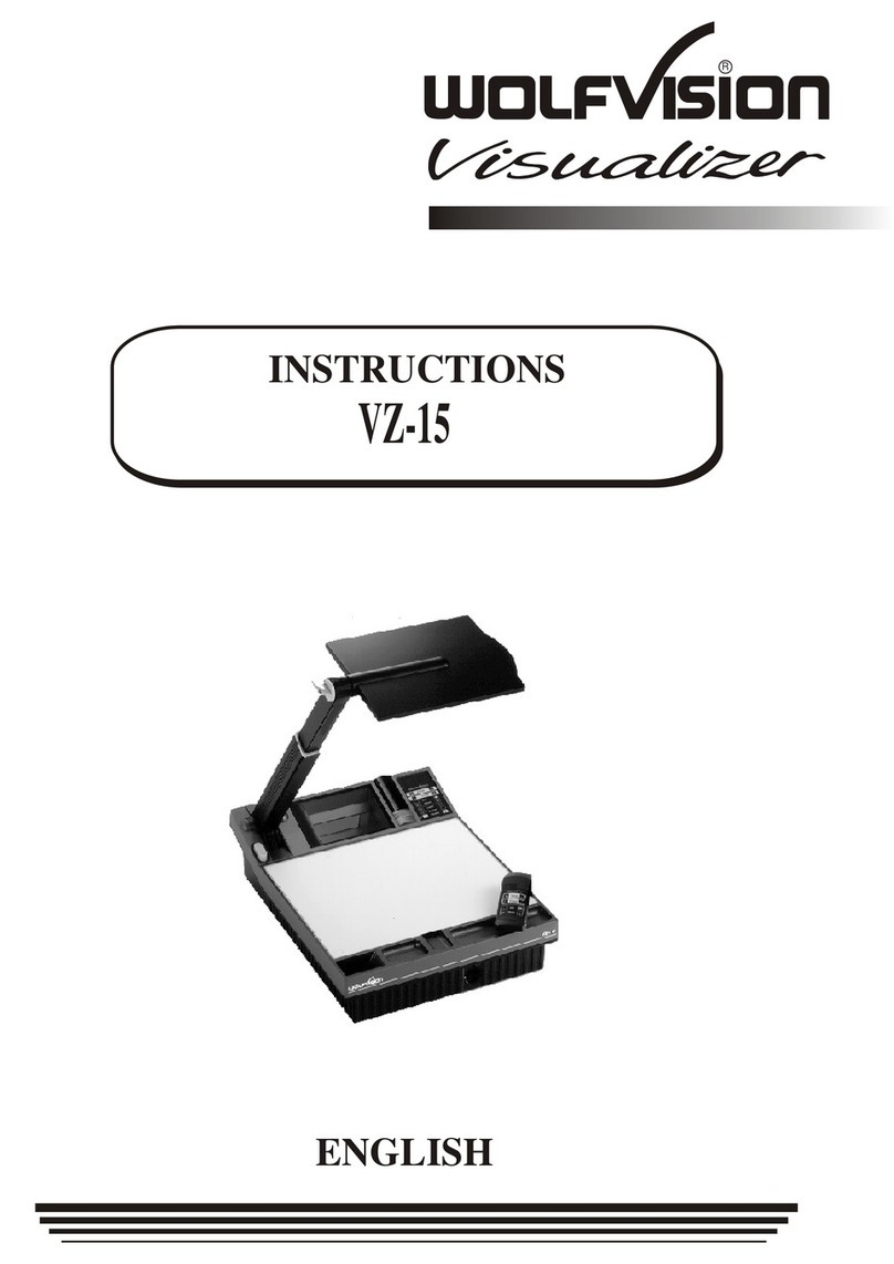
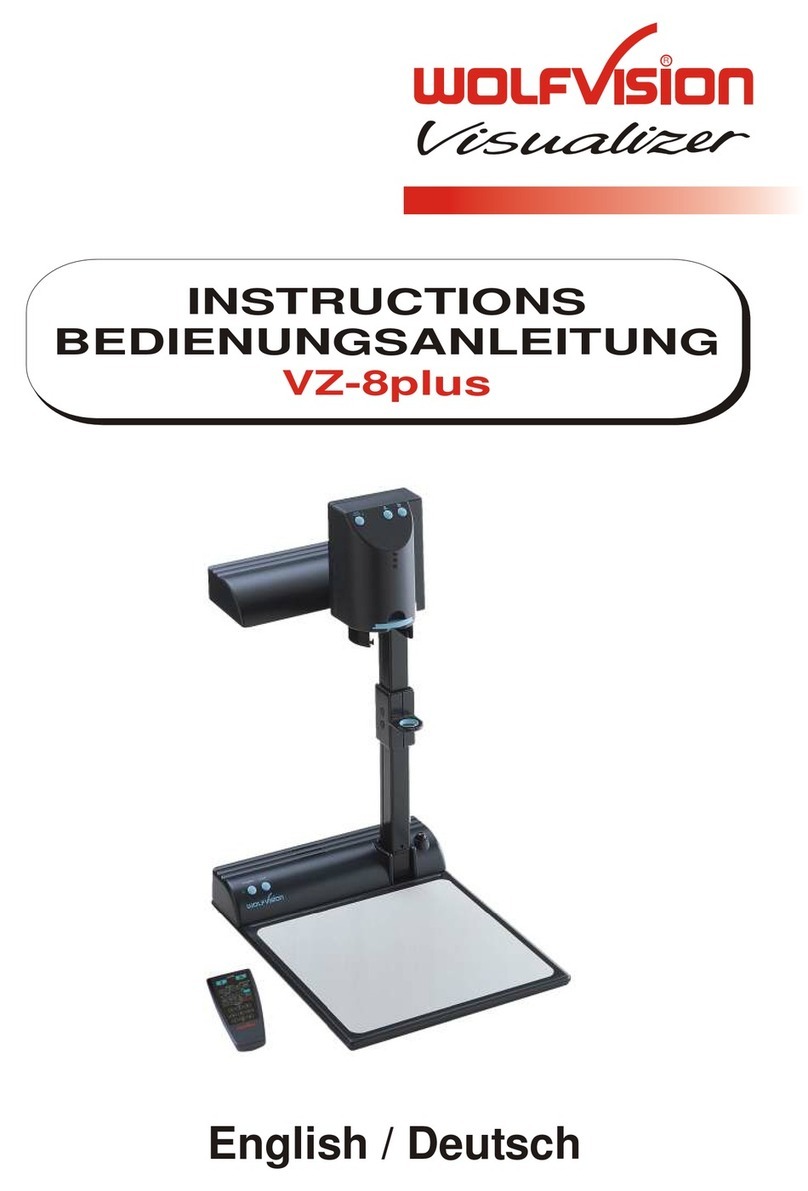
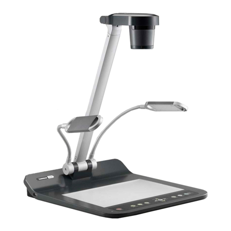
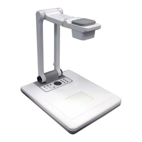
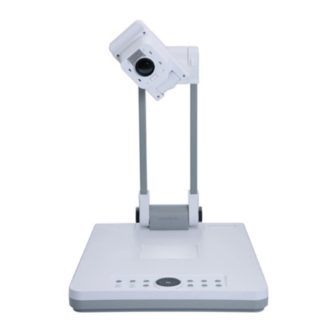
WolfVision VZ-9plus3 User manual

Check out our Internet Homepage for additional information
www.wolfvision.com/support
³
VZ-9plus
INSTRUCTIONS
BEDIENUNGSANLEITUNG
INSTRUCTIONS
BEDIENUNGSANLEITUNG
ENGLISH / DEUTSCH
R
³
VZ-9plus

ENGLISH
Please observe the following:
Risk of electric shock
Dangerous voltage inside
WARNING!
Precautions
1
UsethisVisualizeronlywiththecorrectvoltageasshownonthetypelabel!
DonotexposetheVisualizertoheatormoisture!
ProtecttheVisualizerfromexcessiveshocks!
Make sure that sufficient air circulation for cooling the Visualizer is possible (ventilation slots on
thelamphousing)!
If there is any abnormality (abnormal noise, smell, smoke etc.) disconnect the Visualizer from
mainsimmediatelyandcontactyourVisualizerdealer!
Do not use a damaged power supply / power cord. This may cause short circuits or electrical
shocks!
Topreventdanger,donotmodifytheVisualizeroroperatewithoutthecoverpanelfirmlyinplace!
DonotexposetheVisualizertowater,metallicobjectsoranyflammablematerial.
Avoid installing the Visualizer in locations exposed to strong magnetic fields or electrical
currents.
Avoid installing the Visualizer in environments where there is radiation. This could cause
monitorimagedistortionordamagetotheCCDcamera.
Donotpulltheplugfromthepowersocketwithwethands!
IftheVisualizerisnotusedforalongtime,disconnectitfrommains!
The external power supply has to be approved by CSAor UL in accordance to CSA22.2-60950 or
UL1950.TheoutputshavetobeLPS(limitedpowersource)rated!
Precautions for laser pointer and laser center marker:
Laser light - Do not stare into beam!
Do not modify the laser! Do not view the laser beam with optical instruments!
Information for laser pointer
FDAaccession number: 9912688-00
This device complies with 21 CFR 1040.10 and 1040.11
Information for synchronized laser markers
The laser beam of the
centre marker exits the
unit through the camera
lens.
The laser beam exits the
remotecontrolthroughthe
smaller (left) opening on
thefront.
Technicaldata:
λ=635-680nm
P<1mW
Θ2mrad
This label will be found on the
underneath of the remote
control.
Technicaldata:
λ=635nm
P<1mW
cw/cp=2-28ms
This label will be
found on the camera
arm.

2
EU 1 483 529 RU 2265284 FR 03 02886
RU 2279602 US 7,035,011 JP 3 096 342
US 7,104,512 TW I 226969 and others
TW I 247964 DE 202 03 785.1
KR 0576806 AT-U 7841
FCCinformation:
Thisdevicecomplieswithpart15oftheFCCrules.Operationissubjecttothefollowing two conditions: (1)
thisdevicemaynotcauseharmfulinterference,and (2) this device must accept any interferencereceived,
includinginterferencethatmaycauseundesiredoperation.
Note:
Thisequipmenthasbeentested and found tocomplywiththelimitsfor a class Bdigitaldevice,pursuantto
part15oftheFCCrules.
Informationtouser:
Theusermanualorinstructionmanualforanintentionalorunintentionalradiatorshallcautiontheuserthat
changes or modifications not expressly approved by the party responsible for compliance could void the
user'sauthoritytooperatetheequipment.
ThisproductisbuiltaccordingtoDirectiveEMCandtoDirectiveelectricalequipment.
Inspections,testsandevaluationareaccordingtoUL60950.CSA22.22-60950
Inspections,testsandevaluationareaccordingtotheCB-Scheme
Inspections,testsandevaluationareaccordingtothePCT-Scheme
Marks on the unit:
Approval
Worldwide Patents
Copyright Information
Copyright©byWolfVision.Allrightsreserved.
WolfVision,WofuVisionand areregisteredtrademarksofWolfVisionHoldingAG,Austria.
No part of this document may be copied, reproduced, or transmitted by any means, without prior written
permissionfromWolfVision.Exceptdocumentationkeptbythepurchaserforbackuppurposes.
In the interest of continuing product improvement, WolfVision reserves the right to change product
specificationswithoutnotice.
Informationinthisdocumentmaychangewithoutnotice.
Disclaimer:WolfVisionshallnotbeliablefortechnicaloreditorialerrorsoromissions.
Theunitsare"MADEINEU/AUSTRIA”
PrintedinAustria,May2010
US
C
L
I
S
T
E
D
9902476
Tested to complywith
FCC standards for
home or office use

PRESET
FREEZE
FOCUS- FOCUS+
EXTERN
MENU
?
AF
Components of the Visualizer
#4
#17
#3
#1
#6
#10
#5
#2
#7
#16
#8
#9
#11
#12
#13 #14
#15
#1 Turn Table / Alternative Antitheft security (found underneath the unit as shown on page 19)
#2 Working surface (see page 7)
#3 IR-remote control (see pages 4, 5 and 18)
#4 LIGHT key (see page 6)
#5 POWER key (see page 6)
#6 IR-receiver base
#7 Preview monitor (see page 7)
#8 Light field for slides (see page 7)
#9 Connectors (on the back as shown on next page)
#10 Pull ring to lift the arm up/down (see page 7)
#11 Close up lens for camera (see page 8)
#12 Camera keys (see page 6)
#13 Zoom wheel (see page 6)
#14 IR-receiver camera head
#15 Light source (see page 18)
#16 Slot for Kensington lock® (see page 19)
#17 USB port to Client (to peripheral devices, for external storage units) (see pages 11 and 17)
3

4
Connectors (#9)
#18 RS-232 serial control input RS232 (see page 15)
#19 LAN port (see page 13)
#20
#21 USB-port to Host (to computer) (see page 13)
#22 RGB output (15pin) (see pages 14 and 15)
#23 DVI-I output (see page 14)
#24 (see page 15)
#25 Power connection 12V
#26 DC-output for lightbox (see page 17)
10/100 TBase
USB port to Client (to peripheral devices, for external storage units) (see pages 11 and 17)
External Input for Computer RGB-signals (15pin)
#35
#34 #37
#38
#31
#30 #39
#41
#28
#27 #42
#40
EXTERN POWER
TELE WIDE
LASER
IRIS
FREEZE
12 3
A
A
MEMORY
123
456
789
PRESETS IMAGE TURN
VIEW
#36
AF FOCUS
#33
#32
HELP
MENU
ENTER
SNAPSHOT
Infrared Remote Control (#3)
#29
LAN DVI
RGB
USB EXTERN
RS-232 POWER LB
#22
#21 #25 #26
#23
#19
#18 #24#20

5
#27 EXTERNkey/MENUkey
SwitchesbetweenVisualizerimageandexternalinput(formoredetails-seepage15).
PressingEXTERNkeyfor2secondactivatestheon-screenmenu(seepage16).
#28 HELP/RESETkeyforon-screenmenu(doublefunctionofMemorykeys)
While you are in the on-screen menu you can activate the on-screen help by pressing the HELP key.
Pressingthiskeyfor2secondsresetstheselectedmenuitem(seepage16).
#29 MENUNAVIGATIONkeys(MEMORYkeys2,4,6and8)
Fornavigatingthroughtheon-screenmenu(seepage16).
#30 FREEZEkey
Freezesthecurrentimage(seepage10).
#31 VIEWkey
FordisplayingallpicturesofthememoryassplitimageandtostarttheViewmode(seepage11).
#32 AUTOFOCUS(AF)key
PressingthiskeyactivatestheAutoFocus(seepage9).
#33 SNAPSHOTkey
PressingthiskeyactivatestheSNAPSHOTfunction(seepage11).
#34 PRESETkeys(programmablesettings)
For storing a preset, press one of the PRESET keys for more than 2 seconds. For recalling a preset, press
thePRESETkeyquickly(seepage9).
#35 ZOOMkeys
UsingtheZOOMkeysalsoswitchesautoirisonagain.
#36 LASERPOINTERkey
Important:Donotstaredirectlyintothelaserbeam.Thisishazardousforyoureyes!
#37 IMAGETURNmodekey
Forpickingupvertical(portrait)pageswithhigherresolution(seepage12).
#38 ManualFOCUSkeys
Forfocusingthepicture(seepage9).
#39 ManualIRISkeys(brightnessadjustment)
WhentheIRIS keysarepressed,the Visualizerswitchesofftheauto irisfunction.Thenexttimethe ZOOM
keysareusedtheautoirisisswitchedonagain(seepage9).
Forspecialists: Thebehaviouroftheiriscanbechangedintheon-screenmenu.
Theoverallirislevelcanbechangedintheon-screenmenu(seepage16).
#40 MEMORYkeys1-9
Forsavingandrecallingpictures(seepage11).
#41 ENTERkey(doublefunctionofMemorykeys)
SamefunctionastherightNavigationkey(MEMORYkeyNo.6)(seepage16).
#42 POWERkey
Pressingthiskeyswitchestheunitonandoff.
Whenswitchingontheunit,theVisualizerrunsthepower-onpreset.
If you want to work with more than one Visualizer in the same room, the units should be set to different
infraredcodes,inordertocontrolthemallindividually.
Tochangethe IRcode,enterthe "Misc.Settings"and setthe"IRCode"toA,B,C or
D (code A is default). To change the IR code on the remote control, simultaneously press PRESET 1,
PRESET2 andZOOMTELE
ressPRESET1,PRESET2andZOOMWIDE
on-screenmenu,go to
(#34) (#35).Eachtimethiskeycombinationisused,thecodeswitchesfromA
toB,C,D...A...intheordergiven.
ForresettingtheremotecontroltocodeA,simultaneouslyp .
TheLED showstheselectedcode(itflashesonetimeforcodeA,twotimesforcodeB,three timesforcode
CandfourtimesforcodeD).
Different IR Codes
Keys on the IR-Remote Control
#13 ZOOMWHEEL
Turnthewheeldowntozoomin(TELE),anduptozoomout(WIDE).Themore
you turn the ZOOM WHEEL, the faster the zooming works. Using the ZOOM
keys(wheel)alsoswitchesautoirisonagain.
#43 FREEZEkey/menu:selectkey-left
Freezes the current image. The FREEZE light indicates if the FREEZE-mode
isactivated.
Whenon-screenmenuisactivated,itworksasselectkey(seepage16).
#44 PRESETkey/menu:selectkey-right
For storing the preset, press the PRESET key for more than 2 seconds. For
recallingthepreset,pressthePRESETkeyquickly(seepage9).
Whenon-screenmenuisactivated,itworksasselectkey
#45 ManualFOCUSkeys/menu:navigationkey-upanddown
When the Manual FOCUS keys are pressed the Visualizer switches off the
autofocusfunction.
UsingtheAF-keyswitchestheautofocusfunctiononagain
When the on-screen menu is activated, it functions as navigation keys
#46 AUTOFOCUS(AF)key/menu:helpkey
Switches the auto focus on and off.TheAF light indicates if theAF is switched
on .
When on-screen menu is activated, it functions as Help key. Pressing this key
for2secondsresetstheselectedmenuitem
#47 EXTERNkey/menukey
Switches between Visualizer image and external input (for more details - see
page15).
TheEXTINlightindicatesthatasignalfromtheexternalinputisshown.
Pressingthiskeyfor2secondactivatestheon-screenmenu(seepage16).
(seepage16).
(seepage9). (see
page16).
(seepage9)
(seepage16).
Keys on the Visualizer
Base
Camera Head
One of the great features of WolfVision's Portable Visualizers is that only the most necessary keys are on
theunititself.Thereforeanyonecanuseitwithoutinstructions.
For more experienced users there are some additional functions on the remote control of the Visualizer.
Nearlyallfunctionsontheremotecontrolcanalsobecontrolledthroughthekeysonthecamerahead:
ThePOWERandtheLIGHTkeysarecapacitivekeys,justtouchittoswitch(keepkeyareaclear).
#4 LIGHTkey
Switchesthetoplightonandoff.
It
(seepage10).
Pleasenote,whenactivatingtheslidelightfield,theVisualizerzoomstoslidepicturesize.
#5 POWERkey
Switchestheunitonandoff.WhenswitchingtheunitontheVisualizerautomaticallyrunspower-onpreset.
togglesbetweentoplight,lightfieldforslidesandlightoff.
In case a external (optional) WolfVision light box is connected, the LIGHT key toggles between top light,
externalWolfVisionlightbox,lightfieldforslidesandlightoff.
TheLIGHTkeyalsoworksasONEPUSHWHITEBALANCEkeyifpressedfor2seconds
6
#47
#46
#44
#13
#45
#44
Standard mode
#47
#46
#44
#13
#45
#44
Menu mode

Power-on preset:
The power-on preset is automatically activated when switching on the unit.
The settings are: zoom size: approx. 20 x 15 cm (DIN A5), autofocus: on, auto iris: on.
As soon as the Power Indication LED stays green illuminated, you can start working with the Visualizer.
The behavior of the unit once the power has been supplied or after the POWER key has been pressed
can be changed in the unit's on-screen menu (see page 16).
Setting Up the Visualizer
TheworkingsurfaceoftheVisualizer(#2)hasaspecialcrystallinewhitecolor,whichisespeciallydesigned
forperfectreproductionoftransparencies.
Inthefollowingcases,anoptionallightboxisrecommended:
-Ifthetransparencyisverydark
-Ifthetransparencyisverywavyandcausesreflections
-Iftheroomlightcausesreflectionsonatransparency
Working Surface
Slide
Place the slide onto the built-in light field, turn the camera head until
theslideisinthemiddleoftherecordedimageandswitchontheback
light by touching twice the LIGHT key (#4). The camera zooms the
slide automatically in. The camera automatically focuses on the
slide.
Picking-up Slides
The synchronized laser markers makes positioning of objects very
easy by marking the corners of the picked-up image on the working
surface. The laser center marker zooms synchronous to the camera
zoomandshowsthe4:3and16:10pick-upsizeofthecamera.
Additionally the built-in LCD monitor eliminates the need for an extra
controlmonitor.Thismonitorcanshowdifferentsignals,like“external
in”-image, stored-image or life-image (selectable in the on-screen
menu-seepage16).The on-screenmenuisalsovisibleonthisLCD
monitor.
Positioning on the working surface
1. Connect the power pack to the power-input (#25).
2. Connect your display device (projector, monitor, video
conferencing unit etc.) to the appropriate output of
the Visualizer (#19, #21, #22 or #23).
IMPORTANT:
For choosing the right output please read the
detailed description on page 14!
3. Using the pull pad (#10) only to lift the arm upwards.
Camera head and light automatically move into the
working position. The VZ-9plus³ is switched on
automatically. (Alternative the Visualizer can be switched on by
touching the POWER key.)
IMPORTANT:
To fold the Visualizer, use pull pad only (#10)!
#9
PRESET
FREEZE
FOCUS- FOCUS+
EXTERN
MENU
?
AF
Monitor
#9
PRESET
FREEZE
FOCUS- FOCUS+
EXTERN
MENU
?
AF
7

Shooting Area Outside of the Working Surface
Eliminatingreflections
In order to eliminate reflections (on high gloss photographs etc.) just turn
thelightupwardsordownwardsslightly(defaultpositionishorizontal).
It is also possible to move the document and rotate the camera head to
thecenterofthedesiredpick-upareatoeliminatereflections.
The curvature of the working plate is special designed to eliminate
reflections.
Please note that reflections can also be caused by general room lighting
conditions.
Shooting Area on the Working Surface
Close-upadaptorlens
For shooting an object outside of the working surface, the close up lens
(#11) has to be tipped up. It is impossible to remove the lens completely
fromtheunitandthereforeitcannotgetlost.
WhenusingtheVisualizertoagainrecordontheworkingsurface,putthe
closeuplensbacktoitsoriginalposition.
The camera can be tilted by 290° (110° to the speaker and 180° to the
audience).
Turningthelight/flexibleviewingangle
In order to enable recordings with illumination outside of the working
surface,thelightoftheVisualizercanbeturnedvertically.
To record at a lower viewing angle than the normal working position, just
fold the arm of the Visualizer as much as required, turn the camera head
andthelighttopickupthedesiredobject.
ImageFlip
By turning the camera head to record in front of the Visualizer, the image
will automatically be turned 180 degrees (”image flip”). This feature is
very useful for recording the face of the presenter or objects hanging on
thewallbehindtheunit.
Turntable
TheturntableoftheVisualizerallowsforhorizontalpanshotswhenusing
the Visualizer as a camera to record outside of the working surface. It is
also very useful when two people, sitting on the same table, alternately
workwiththeunit.
Whentheunitisdelivered,theturntableisunlocked
(seepage19tolocktheturntable).
#9
PRESET
FREEZE
FOCUS- FOCUS+
EXTERN
MENU
?
AF
8
∞

Please note that the Visualizer has an optical 16x zoom. The digital 4x zoom increases the overall zoom
range to a 64x zoom. The smallest pickup size on the working surface without digital zoom is 25 x 19mm
(1" x 0.8"). When you zoom in further the digital zoom is automatically activated and the smallest pickup
size is 6 x 4mm (0.23" x 0.16"). However please be aware that when the digital zoom is used, the
resolution of the picture is not as good as before. The default setting displays a message on-screen when
youareinthedigitalzoommode.
Stillpicturesinthememorycanalsobedigitallyzoomed.
You can change the behavior of the Visualizer in the digital zoom mode in the on-screen menu (see page
16).
.
TheVisualizeroffersthepossibilitytostorethecurrentsettingsasaPresetandrecallthembyjustpressing
therespectivePRESETkey(#34)ontheremotecontrol.
Preset1canbecontrolledwiththePRESETkeyonthecamerahead(#44).
For storing a reset adjust y function as required and then PRESET key for 2
seconds .Anon-screenmessage informyouwhenthePresetisstored.
As mentioned above, when presets are stored all current settings such as zoom, focus, iris etc. are also
stored. Contrary to this, a user also has the opportunity to assign specific functions such as "TEXT",
"LIGHT”,"NEGATIVE","NEGATIVE/BLUE", "BLACK/WHITE","FREEZE"etc.toaPRESETkeyintheon-
screenmenuoftheVisualizer(seepage16).
p : an press any one of the s
ormore will
Preset Function 12 3
PRESETS
Digital Zoom TELE WIDE
WolfVision Visualizers are equipped with an auto iris. This means that the brightness of the camera image
adjusts automatically. Using the IRIS keys (#39) the auto iris function is switched off. In this mode the Iris
canbeadjustedmanually.
WhenusingtheZOOMkeys(#35)orZOOMwheel(#13)theautoirisfunctionisswitchedonagain.
The standard auto iris level can be set brighter or darker in the unit's on-screen menu. When picking up
areas with bright spot, Back Light Compensation can be switched on in the unit‘s on-screen menu - see
page16andon-screenhelp.
IRIS
Auto Iris / Manual Iris
Text Mode
For improving the readability of text, sketches or x-rays, the text mode can be activated by pressing the
assignedPRESETkey .
Thismodeenhancesthecontrastofthepicture.Pleasenotethat thecolorsare nowdarkerthan usual.To
switch off the text enhancement mode, press the again. When the text
enhancementmodeisinuse,themessage"TEXT"ispermanetlydisplayedonthebuilt-inLCDmonitor.
Thisshould remind the user to switch offthetext mode when it is no longer required. It should alsoprevent
userstryingtocorrectdarkcolorsbyopeningtheiris,resultinginapoorlyadjustedpicture.
(TEXT)
assigned PRESET key (TEXT)
Focusing / Autofocus
AF
Please note that objects with very low contrast (like blank sheet of paper) are difficult to focus. If the
autofocusdoesnotworkjustmovetheobjectslightly.
For special applications the autofocus can also be switched off using the on/off switch (#32 or #46). The
autofocusisalsoswitchedoffwhenthemanualFOCUSkeys(#38or#45)areused.
9

Correctwhitebalanceadjustmentisimportantforanexactcolorreproduction!
Foranexactwhitebalance,atleast10%oftherecordedimageshouldbewhite.
For a precise fixed white balance adjustment use the "One Push" white balance. This can be done by
pressingtheLIGHTkey(#4)(orassignedPRESETkey)for2seconds.Whenthewhitebalanceisstoredan
on-screen message appears. Setting a "One Push" white balance switches off the "Auto Tracking" mode
(whentheunitisswitchedoffandonagainthe"AutoTracking"modewillbereactivated).
For specialists: The Visualizer can be switched between "Auto Tracking", "One Push" and "Manual"
white balance mode in the on-screen menu (see page 16). If you work with negative transparencies and a
light box, use a blank (black in the image) part of the negative film for white balance adjustment! The "one
Push"whitebalancewillbeseparatelyadjustedandstoredfortoplight,slideboxandexternallightbox.
Each time the lighting condition changes, the Visualizer's camera must readjust its white balance, in order
to optimize the color reproduction. The lighting condition (color temperature) changes, for example, if
changing between the Visualizer's light and an external lightbox (bottom light) or if the room light is turning
onoroff.
ThestandardsettingoftheVisualizeris"AutoTracking"whitebalance.
Normally there is no need for a manual white balance adjustment. However, if the colors on the screen still
appeartobewrong,thewhitebalancecanbeadjustedmanually(one-push):
HintstoperformaOne-Pushwhitebalance:
Toplight:
Zoominonawhiteobject(i.e.asheetofpaper)untilthereisonly white on the screen and press the
for2seconds.
Lightboxwithtransparencies:
Turn off the light of the Visualizer with the assigned PRESET key and switch on the lightbox. Remove
everythingfromthe lightbox,zoomto thesmallestpicturesize untilthereisonly whiteonthescreen and
pressthe for2seconds.
Lightboxwithx-rays:
Turn off the light of the Visualizer and switch on the lightbox. Place an x-ray on the light box, zoom out
untilthewholex-rayispickedupandpressthe for2seconds.
Please note: False colors can also be due to wrong color settings of your projector or monitor. It is
recommendedtoadjustthe white balanceoftheVisualizer at firstandiftheresults are stillnotsatisfactory,
themonitororprojectorshouldbechecked.
Thismeansthatthewhitebalance
iscontinuouslyadjustedautomatically.
LIGHTkey
LIGHTkey
LIGHTkey
White Balance Adjustment
10
The current image can be captured by pressing the FREEZE-key (#30 or #43). The FREEZE LED is
illuminatedgreenwhenthefreezefunctionisactivated.
The DVI- and RGB outputs of the Visualizer can be set to output different signals. This can be used for a
"LivePicturetoFreezePictureComparison"ontwomonitorsorscreenswithjustoneVisualizer.
Whileonemonitororscreendisplaysa"freeze"imagethatcanbeusedforcomparison,anothermonitoror
screencanbeusedforpresentingtheliveimagefromtheVisualizer.
ThesettingsoftheFREEZEfunctioncanbechangedintheon-screenmenu(seepage16).
Freeze / Live to Freeze Comparison (two display devices)
FREEZE
IMPORTANT

11
You can store 9 images in the internal memory and recall them by just pressing the respective numerical
keyontheremotecontrolquickly.
Storinganimage: PressoneoftheMEMORYkeys(#40)foratleast2seconds
Recallinganimage: PressoneoftheMEMORYkeys(#40)quickly
WhenpressingtheVIEWkeyfor4seconds,apop-upmessage appearsonthescreenaskingifyouwould
like to "Erase internal image memory" (grey pictures). Still pictures in the memory can also be digitally
zoomedwiththezoomkeys/wheel.
The functional settings of memory erasing can be changed in the on-screen menu (manually or
automaticallyoneverypower-on).
The built-in memory can be extended by an external USB storage device like an USB stick.
Please note, the USB storage device can be connected to the the USB port on the connector panel #20 or
onthesideoftheunit#17,butnotonbothatthesametime.
Image Memory
Built-inMemory(externalstoragedevicenotconnected)
By pressing the SNAPSHOT key the current image is stored in the next free memory. When all 9 memory
locations are full, a message appears on the screen "Memory FULL!", "Hold SNAPSHOT to erase oldest".
BykeepingtheSNAPSHOTkeypressedfor2seconds,thememory OverwriteModewill beactivated.The
stored pictures can be overwritten by pressing the SNAPSHOTkey quickly. The Memory Overwrite Mode
canbedeactivatedbykeepingtheSNAPSHOTkeypressedfor2secondsorbyswitchingofftheunit.
Externalstoragedeviceconnected
BypressingtheSNAPSHOTkeythecurrentimageisbestoredontheUSBdeviceandamessageappears
onthescreen.ThestoredimagesareinJPGformatandcanbeedited/viewedonacomputer.
Allpicturesarestoredwithdateandtimestamp.
The properties of the USB functions can be changed in the on-screen menu (Advanced Settings - USB
StickSettings),likedefault picture folder(documentdirectory)andthe file names("WV"andconsecutively
numbered).
Snapshot
Pressing the VIEW key will start the VIEW mode. A split image with 3x3
stored pictures is displayed. Additionally a status line with picture
information is displayed on top of the screen.
By pressing the MENU key you can organize directories (set current used directory, create and delete
directories), move pictures from one directory to another one, delete pictures, format the connected USB
storagedeviceandstartthePresentationmode.
To start the Presentation mode, select the „Presentation” line in the VIEW menu. With the automatic
presentation mode, all images from the selected folder are shown with a pre-defined changing interval (5s
to 100s). In the manual mode, use the arrow keys (MEMORY 4/6) to change to the next/previous image.
Pictures from the internal
memory are shown with a red frame and pictures from the USB storage
devicewithablueframe.
To select one of the currently displayed images move the colored frame
withtheNAVIGATIONkeysandthenselecttheENTERkey.Stillpicturesin
thememorycanalsobedigitallyzoomedwiththezoomkeys/wheel.
Toscrolltothepreviousornext3x3imagesplitscreenortoswitchbetween
internal/USBmemory,usethedoublearrowkeys(MEMORY1/3).
PressingtheVIEWkeywhilstthePresentationisrunningswitchestemporarilytotheliveimage.
To change the current used directoryselect the „Directory” line in the VIEW menu.Enter „Set Current Dir.”,
choosethedesireddirectoryandconfirmtheline„Selectdirectory”.
Pleasenote,theavailablefunctionsarelimitedwhennoUSBstoragedeviceisconnected.
Pleasenote,formattingtheUSBstoragedevicewilldeletealldata.
Supportedfilesystems:FAT16andFAT32
SupportedpicturefileformatisJPGformat.
Split image of 9 picture memory
View Mode

12
Built-in Digital Scaler (for Extern-in and USB-Stick)
The Visualizer has a built-in digital image scaler which can process the signal from the external input and
output it in the same mode as the Visualizer image (For example: If the Visualizer is set to output an SXGA
image to the projector and the computer outputs an XGA signal, the scaler of the Visualizer converts the
XGA image of the computer to SXGA. As a result the projector does not readjust the input mode when
switchingbetweentheVisualizerandcomputerimage).
In addition images on a connected USB-stick are automatically scaled to the current output mode of the
Visualizer.
TheoutputresolutionoftheVisualizercanbechangedintheon-screenmenu(seepage16).
Integrated Seamless Switch
TheVisualizerhasanintegratedSeamlessSwitch.
This allows for a seamless transition (fade-over/dissolve effect) when switching between the Visualizer
image, the image from the external input, the internal image memory of the Visualizer and images on an
USB-stick.Thisfeaturemakesswitchingfromonemediatotheotherappearverysmoothandprofessional.
ThebehavioroftheVisualizercanbechangedintheon-screenmenu(seepage16).
Picking up a complete vertical (portrait) document or A4 page has always been a critical issue for a
Visualizer because the image s always picked up in a horizontal (landscape) format.
The camera could only use 50% of its pixels to pick up a vertical (portrait) page. WolfVision's
Just place your document (or other vertical object)
º
wa "Image turn"
modesolvesthisproblem. on the working surface horizontally and zoom in on it
completely, so that approx. 90% of the pixels of the built-in camera are used to pick up the document, then
presstheIMAGETURNkey(#37).TheVisualizerturnsthepictureelectronically90 andoutputsitcorrectly
withamuchhigherresolutionthaninnormalmode.Theleftandrightmarginswillbeblack.
Image Turn Mode (for higher resolution)
IMAGE TURN
A
A
A
A
AA
Working surface: Output picture:
Normal mode:
Image turn mode:
Only 50% of the
pixels are used to
pick up the document
90% of the pixels
are used to pick
up the document
The Picture in Picture Mode offers the possibility to show two different
pictures at the same time on one screen. Just press
to activate the Picture in Picture mode. The
current picture (i.e. external signal, image memory) will be shown in the
lowerleftcornerand theliveimagewill be shownintheupper rightcorner.
Thesizeoftheliveimageismuchbigger.
The content of the live image can be changed i.e. by recalling a stored
imagememory.
Following comparisons are possible: Extern-In, image memory, live
image.Thecontentfromthesmallimageisfrozen,exceptwhenthesignal
fromtheExtern-Inisshown.
the assigned
PRESET key (PiP Mode)
Picture in Picture (PiP)

13
USB Device Port (to the computer)
TheUSBdeviceportcanbeusedfordirectconnectionsbetweentheVisualizerandacomputer.Thisway,a
Visualizercanbecontrolledandcanbeusedasascannerfor3-dimensionalobjects.ImagesinJPG,TIFor
BMPformatcanbetakeninafractionofasecond-muchfasterthanwithadesktopscanner.
WolfVision's USB Software (Connectivity Software) works under Windows 2000, XP, Vista and 7 (32 and
64-bit) as well as Apple Macintosh. It is fully TWAIN/WIA compatible. This is important when using
Visualizers in connection with graphic programs such as Photoshop, or for connecting them to Interactive
Whiteboards(SmartBoards).
The fast USB 2.0 port can also output live motion. WolfVision‘s Connectivity Software can storeAVI files
and includes a video capture driver. You can view and save the live image from the Visualizer on your
computerinalmosteverymodernvideoeditingsoftware.
PleasedownloadthelatestversionoftheWolfVisionConnectivitySoftwarefrom:
www.wolfvision.com/support.
Pictures which are stored with the WolfVision Connectivity Software includes EXIF data, if file format JPG
orTIFFisused.Includeddataare:
Manufacturer=WolfVision
Visualizermodel(inclusiveserialnumber) =i.e.VZ-9plus-3(00103701)
Firmwareversion=i.e.V1.11a
Dateandtimeofcreate=i.e.2010-04-1811:06:29(yyyy-mm-ddhh:mm:ss)
Please note, the computer can be connected on the USB-plug on the connector panel #20 or on the side
#17,butnotonbothatthesametime.
Ethernet / LAN Port 10BASE-T/100Base-TX
The LAN port (#19) makes the Visualizer a part of the internal computer network and it can be used for
communicationovertheInternet,ifitisassignedanofficial(WAN)IPaddress.
Administrators of a larger number of Visualizers can use the LAN port to control, support and update all of
theirunitsfromtheirlocaldesktopPC.
The list of applications for the Visualizers LAN port is constantly increasing. It can be used for controlling,
capturing still images, viewing live video streams, firmware updates, adjustments, menu settings and
maintenancepurposes.
Thefollowingprotocolsaresupported:TCP/IP,ICMPandARP.
dinternetb are: /Firefox
InordertopreventunauthorizedusersfromloggingintotheVisualizeroverthe network,itispossibletoset
administratoranduserpasswords.ThetransmissionofthepasswordsoverLANisencryptedwithMd5.
TheVisualizerofferstreamingofliveimagesinSinglecast(Unicast)andMulticastmode.
(Technical Background:InSinglecastmode eachcomputeropensaseparate connectiontotheVisualizer,
whichrequiresalotofbandwidthifmanyclientsareconnected.Multicastislike a broadcast - many clients
are watching the same video stream. In Multicast mode the bandwidth is always the same, no matter how
many computers are connected. However as many routers do not support Multicast it can not be used
everywhere.Thisiswhybothstreamingmodesareimportant.)
Supporte rowsers InternetExplorer,NetscapeNavigatorandMozilla .
Bydefault,DHCPisactivatedtoreceiveallnetworksettingsautomatically.
PossibleimagetransferresolutionuptoSXGA-(1280x960).
Please check the separate description of "Built-In WebServer" on our internet homepage at:
www.wolfvision.com/support(oronthesuppliedCD-Rom).
ForfullfunctionalityJAVAversion1.5.0orhigherisnecessary.

DVI/RGB Output Choosing the Correct Output Mode
14
TheDVIandRGBoutputs(#22and#23)canoutputsignalsinfollowingformats:
-VGA (4:3-640x480pixels)at60Hz
-SVGA (4:3-800x600pixels)at60Hz
-XGA (4:3-1024x768pixels)at60Hz
-SXGA- (4:3-1280x960pixels)at60Hz-nativeimage
-SXGA ( -1280x1024pixels)at60Hz
-SXGA+ (4:3-1400x1050pixels)at60Hz
-UXGA (4:3-1600x1200pixels)at60Hz
-WXGA* (16:10-1280x800pixels)at60Hz-nativeimage
-WXGA (16:9Widescreen-1360x768pixels)at60Hz
-WXGA+ (16:10Widescreen-1440x900pixels)at60Hz
-WSXGA+ (16:10Widescreen-1680x1050pixels)at60Hz
-720p (16:9WidescreenHD/HDTV-1280x720pixels)at50Hzor60Hz-nativeimage
-1080p (16:9WidescreenHD/HDTV-1920x1080pixels)at50Hzor60Hz
-WUXGA (16:10Widescreen-1920x1200pixels)at60Hz
Please note that the Visualizer can not check the
possibleresolution,iftheconnectedunitsorthecables*arenot"PlugandPlay"compatible.IftheVisualizer
cannotdetecttheresolutionoftheconnecteddevice,theoutputissettothedefaultofSXGA-/60Hz.
(*Cableswithplugandplaycompatibilitymusthavea15-pinplugonbothendswithallpinsconnected).
Ifyoucannotusethe"Auto resolution"function,you canselecttheoutputmode manuallyintheon-screen
menuoftheVisualizer(seepage16).
In order to achieve the best picture quality you must set the outputs of the Visualizer to match the native
resolutionofyourdisplayunit(e.g.LCDorDLPprojectorormonitor).
Important:Whatmattersisthenativeresolutionoftheprojectorormonitor,notthemaximumresolutionthat
itcandisplay(incompressedmode).Thenativeresolutionistheactualnumberofpixelsofthebuilt-inLCD
display or DLP chip of a projector or monitor. Most LCD or DLP projectors can also display higher
resolutionsthantheirnativeresolution,butonlyincompressedmodeandwithinferiorpicturequality.
Do NOT set the output of the Visualizer to a higher standard than the native resolution of your
displayunit!
Donot setahigherrefreshrate thanyourmonitoror projectorcan display,otherwisethemonitoror
projectorcanbedamaged!
Followtheinstructionsintheusermanualoftheconnectedunits.
Pleasenote,if 4:3and16:9or16:10resolutionsareused simultaneously, the4:3displayshows blackbars
ontopandbottom.Thisisnecessarytoensurethatalldisplaysshowthesameimagecontent.
5:4
The "Auto resolution" function is activated by default. In this mode the Visualizer continuously checks
which devices are connected to the RGB (#22) and DVI output (#23) and automatically sets the optimal
output mode for each connected device separately.
DVI-I Port
TheDVIPort(#23)suppliesthedigitalandanalogsignal-DVI-I.
1- T.M.D.S. Data2- 9 -T.M.D.S. Data1- 17 - T.M.D.S. Data0-
2- T.M.D.S. Data2+ 10 -T.M.D.S. Data1+ 18 - T.M.D.S. Data0+
3- T.M.D.S. Data2/4 Shield 11 -T.M.D.S. Data1/3 Shield 18 - T.M.D.S. Data0+
4- T.M.D.S. Data4- (*) 12 - T.M.D.S. Data3- (*) 19 - T.M.D.S. Data0/5 Shield
5- T.M.D.S. Data4+(*) 13 - T.M.D.S. Data3+ (*) 20 - T.M.D.S. Data5- (*)
6- DDC Clock 14 - +5V Power 21 - T.M.D.S. Data5+ (*)
7- DDC Data 15 - Ground (return for +5V, 22 - T.M.D.S. Clock+
8- Analog Vertical Sync HSync and Vsync) 23 - T.M.D.S. Clock-
C1 - Analog Red 16 - Hot Plug Detect 24 - Analog Vertical Sync
C4 - Analog Horizontal Sync C2 - Analog Green C3 - Analog Blue
C5 - Analog Ground *...not used
(analog R, G & B return)
m
Pin 24
Pin 8
Pin 1
Pin 9
Pin 17 C4
C1 C2
C3 C5

15
EXTERN
RGB Port
1 - Analog Red video 6 - Red return 11 - N/C Not connected
2 - Analog Green video 7 - Green return 12 - SDA I²C data
3 - Analog Blue video 8 - Blue return 13 - HSync Horizontal sync
4 - N/C Not connected 9 - SENSE +5 V DC from Visualizer 14 - VSync Vertical sync
5 - GND Ground 10 - GND Ground (VSync, DDC) 15 - SCL I²C clock
1
11
5
15
15-pin D-Sub HD
connector female
(front side, unit)
TheEXTERNinput(#24)hasthesamepinassignmentastheRGBoutput(#22).
External Input - EXTERN
A computer can be connected to the External RGB input (#24) of the Visualizer.
By you can switch between the Visualizer image and the image of
theexternalinputtobedisplayedtotheaudience.
TheVisualizerhasabuilt-inA/D-converterinordertodigitizetheanalogRGBsignalfromthecomputerand
outputitontheRGBandDVIoutputsintheselectedsignalformat.
Preferredresolutionis: SXGA-(1280x960)@60Hz
SupportedresolutionsfromVGA(640x480@60Hz) to1080p(1920x1080@60Hz)withseveral resolutions
andrefreshratesinthisrange.
Followingdataareprovided:
Plug&PlayMonitorVESADDC
Monitorname:"WolfVision"
VideoInputDefinition:Analogat0.7Vppandseparatedsynchronizationsignals
Verticalrangelimits:48Hz-86Hz
Horizontalrangelimits:30kHz-121kHz
Maximumpixelclock=170MHz
Gamma=2.2
Preferredresolution:SXGA-(1280x960)@60Hz
pressing the EXTERN-key (#27 or #47) ThePreviewoutputoftheVisualizersalwaysoutputsthe
image of the Visualizer camera, while all other outputs (DVI, RGB etc.) can be set to output an external
image.
This can be used for a "Live Picture to External Picture Comparison" on two monitors or screens with just
one Visualizer. While one monitor or screen displays an external image that can be used for comparison,
anothermonitororscreencanbeusedforpresentingtheimagefromtheVisualizer.
ThesettingsoftheVisualizercanbechangedintheon-screenmenu(seepage16).
The output level on VGAand Preview output can be adjusted to match exactly 700mV. This can be helpful
tobalancedifferentimagebrightnessi.e.whenusingexternalinput.
Forexactadjustment,pleaseuseexternalmeasurementequipment.
Range:85%to100% (on-screenextramenu-seepage16)
Thecompleteserialprotocolcanbefoundonourinternetwebsiteunder:www.wolfvision.com/support
The serial port (#18) can be used to control the Visualizer through an external device, such as a room
controlsystemthatisusedtointegrateconferencerooms.
Pins: 2:RX, 3:TX, 5:GND
BaudRate: 9200,19200,38400,57600or115200(selectable)
databits:8,stopbit:1,parity:no
Thebaudratecanbechangedintheon-screenextramenu (seepage16).
RS-232, Serial Control Input
9-pin D-Sub connector
on unit male
(front side)
5
9
1
6

Forregularuseofthe WolfVision Visualizer,itisnotnecessarytogointotheVisualizer'smenu andchange
settings.Inexperiencedusersshouldnotmakeanyadjustmentshere.
Toentertheon-screenmenupressthe MENU key (#27 or #47)foronesecond.SettingsoftheVisualizer's
basic functions and the built-in camera can be made here using the navigation keys on the camera head
(#43,#44and#45)orthe4SELECTkeysontheremotecontrol(=thenumericalkeyswithredarrows#27).
Please note that some basic settings in the menu can only be changed if you set the menu item "Format
protect"to"OFF"first.
Ifmoreinformationonafunctionintheon-screenmenuisrequired,setthecursorintherespectivelineand
press the HELP key (#28 or #46). Adetailed description of this function appears on the screen. If you want
toresettheselecteditemtothedefaultsetting,presstheHELPkey(#28or#46)for2seconds.
BypressingtheMENUkeyfor4secondstheExtraMenuappears.
IntheExtraMenu,settingslikebaudratecanbechanged.
The functions of the on-screen menu are not described in detail in this user manual as the help menu is an
integrated part of the Visualizer's software (firmware). The information you see on your screen always
belongstothecurrentVisualizerfirmware.
In the "Power Control" settings of the on-screen menu you can select that the Visualizer will be
automaticallyswitchedoffafteracertainamountoftime.
All settings in the on-screen menu can be set back to the factory defaults. "Recall Factory Settings" is one
itemintheon-screen menu (alternatively, the menucanberesetbykeep pressed bothFOCUSkeys(#38)
simultaneouslyfor2seconds,releaseitandpresstheMEMORY4key(#29)).
Ifyouonlywanttoresettheitemthatiscurrentlyselectedtothedefaultsetting,presstheHELPkey(#28or
#46)for2seconds!
The following chapter is for experienced users only:
ON-SCREEN MENU / ON-SCREEN HELP
Changing the Color Settings
Auto Power-off
RESET OF ON-SCREEN MENU SETTINGS
16
In the "Preset Settings" the Preset keys can be assigned specific functions such as "NEGATIVE/BLUE",
BLACK/WHITE","LIGHT", PiP , TEXT ,etc." " " "
Preset Settings
If the picture on your screen appear to be too light or too dark or the color saturation is not correct, you can
changetheColorMode in the on-screenmenu(ColorSettings).Pre-settings are PRESENTATION(higher
colorsaturation),NATURAL(sRGB)andVIDEOCONF(forvideoconferencingsystems).
AlternativeGammaandSaturationcanbechangedmanually.
The output image of the Visualizers can be switched from positive to negative in the on-screen menu. In
addition, the background of a negative image can be switched to blue for better readability of text. You can
alsoswitchbetweencolororblackandwhiteintheon-screenmenu.
TIP:Ifyouoftenswitchtonegative,negative/blueorblack/whiteimagesyoucanassignthisfunctiontoone
ofthePresetkeysintheon-screenmenu.
Switching to Negative, Negative/Blue and Black/White

17
Saving Visualizer Settings onto a USB-Stick
The Visualizer offers the opportunity to save menu settings and preset settings onto a USB stick (USB
storagedevice)asanXMLfile.
Change the settings to the desired values and store it on the USB stick (in the on-screen menu,Advanced
Settings/USBStickSettings).
WhenyouconnecttheUSBstickwiththepreparedXML-file,anon-screenmessagewillpop-up.
AssoonastheUSB-stickisremoved,theprevioussettingsarerestored.
ThesettingsoftheVisualizercanbechangedintheon-screenmenu(seepage16).
Dimensions
Technical Specifications are Subject to Change!
closed:
working position:
637
25 1/8"
333
13 1/8"
155 ±10
6 1/8"
±3/8"
408
16 1/8"
Connect the power cord of the WolfVision lightbox to the lightbox connector (#26) on the back of the
Visualizer. The LIGHT key (#4) of the Visualizer can now be used to switch between the light of the
VisualizerandthelightoftheWolfVisionlightbox.
TouchingtheLIGHTkeytwicetoactivatethelightbox.
Whenusingalightboxwithaseparatepowersupply besurethat thelightof theVisualizerisswitchedoffto
preventreflections.
External WolfVision Lightboxes (optional)

1. Remove the power cord of the Visualizer
2. Remove the lamp cover by turning then pulling the case
CAUTION HOT - ALLOW THE UNIT TO COOL DOWN!
(>60°C / 140°F)!
3. Lift the security ring
4. Change the lamp
Place the new lamp very carefully into the socket
5. Mount the lamp cover in reverse order (pt. 3-1).
Check position of lightning arm (click-stop device).
Lamp type: Halogen lamp 12V/50W at 5000 h average burning life.
inclusive heat shield and security ring.
WolfVision part no.: 102447
18
WARNING:
Never use strong cleaning agents such as acetone or benzene!
These substances can damage the surface and the anti-reflex coating!
Cleaning
Cabinet: Cleanthecabinetbygentlywipingitwithasoft,lintfreecloth.
Lenses: Cleanthelensesbygentlywipingwithasoft,lintfreecloth(donotuseapapertissue!).Cleanby
breathingonthelenstocreatemoisturethenwipewithalintfreecloth(Ifneedbe,useaspecial
opticalcleaneronly!).
Please note that an infrared remote control can only be used up to a certain distance
fromtheunit.ObjectssituatedbetweentheVisualizerandtheinfraredremotecontrol,
andweakbatteries,interferewithreception.
If the Visualizer can only be controlled from a close distance, or if it cannot be
controlled at all with the infrared remote control, you may have to change the
batteries.
Openthecoveronthebackoftheremotecontrolandreplacethetwo
1.5VAAbatterieswithnewones.
Checkthepolarityofthebatteries!
Recyclethebatteries!
Infrared Remote Control
back (open)
-
+
-
+
XX
MAINTENANCE
Changing the Lamp of the Visualizer
The software (firmware) of your Visualizer (including the o ) can easily be upgraded to the
latestversion.ThefirmwareupdatecanbedoneviaUSB,Ethernet(LAN)orRS232.
Firmware update files can be downloaded for free at www.wolfvision.com/support. Updates via USB or
Ethernet/LAN can be made with the WolfVision Connectivity Software, updates via RS232 can be made
withWolfVision'sFirmwareUpdateUtility.Bothtoolscanalsobefoundunderthesamelinkasthefirmware
files.
n-screen HELP
Firmware Upgrades

Anti-theft device 2: table lock bolt
TheVisualizercanbefixedwitha ,sothatitcannotbestolen.
Followtheinstructionsfromthecablelockmanual.
®
securitycableT-barlock(Kensington Lock)
Anti-theft device 1: T-bar lock
slot for lock
The Visualizer can also be fixed onto a table with the
supplied table lock bolt in order to minimize the risk of
theft.
Pleasenotethattheusabledepthofthreadis8mm,donot
screwinmorethanthis.
Suppliedaccessories:
1xSocketheadcapwrench5mm (101684)
1xAllenscrewdriver2,5mm (101685)
1xScrewM8x35 (101686)
1xScrewM8x50 (101687)
2xWasher8.4/16x1.6 (100527)
1xAssemblyinstructionsVZ-9plus³ ( )103259
LockTurntable
Remove the screw from the hole position 2 and insert it
into the specific hole position 1 (the turntable might have
tobeturneduntilthethreadisvisible).
UsesuppliedAllenscrewdriver(2,5mm).
table
(sectional view)
washer 8.4/16x1.6
screw M8x35 or
screw M8x50
Turntable
19
If the unit gets too hot (improper ventilation, or air extraction or too high ambient temperature) a built in
thermalsensorwillswitchoffthelightoftheVisualizer.
Verifythatproperventilationandairextractionisavailableandallowtheunittocool!
Therotationspeedofthebloweristemperaturecontrolled.
Thermostat
attachment
area
21
M8
167
[6 5/8"]
185
[7 1/4"]
Table of contents
Languages:
Other WolfVision Document Camera manuals

WolfVision
WolfVision VZ-27plus User manual

WolfVision
WolfVision VZ-5b User manual

WolfVision
WolfVision VZ-C122 User manual

WolfVision
WolfVision VZ-8plus4 User manual

WolfVision
WolfVision VZ-17 User manual

WolfVision
WolfVision VZ-8plus User manual

WolfVision
WolfVision Visualizer VZ-7D User manual

WolfVision
WolfVision SCB-12 Installation guide

WolfVision
WolfVision Visualizer VZ-15 User manual

WolfVision
WolfVision VZ-C11 User manual