manuals.online logo
Brands
  1. Home
  2. •
  3. Brands
  4. •
  5. Wren
  6. •
  7. Indoor Furnishing
  8. •
  9. Wren TOWER UNIT 2070 User manual

Wren TOWER UNIT 2070 User manual

TOWER UNIT
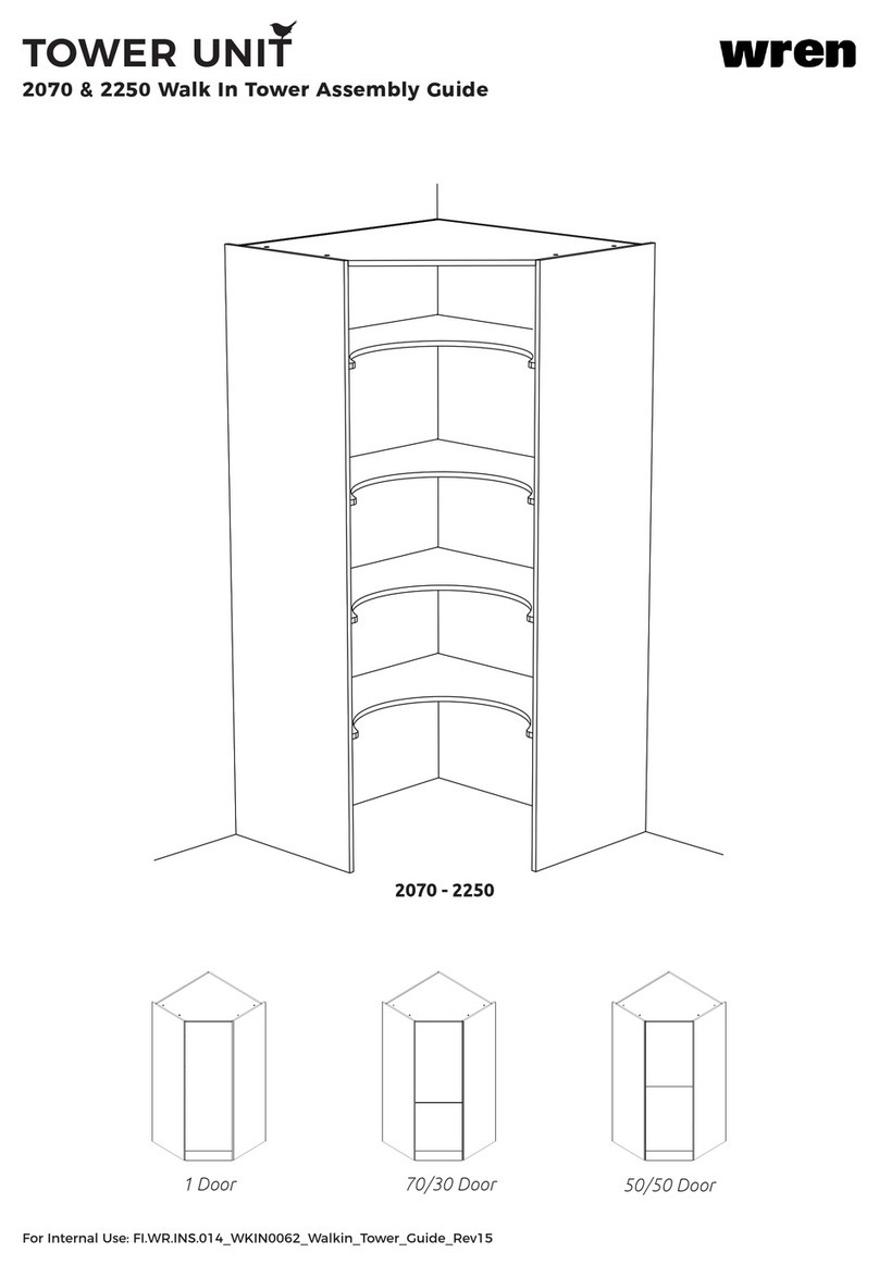
2070 & 2250 Diag Corner Larder with Wine Rack Assembly Guide
For Internal Use: FI.WR.INS.097_WKIN00199_TOWER_45WineRack_AssemblyGuide_Rev11
2070 - 2250
1 Door
50/50 Door
70/30 Door
BEFORE YOU START
INSTALLATION SHOULD BE PERFORMED BY A COMPETENT PERSON ONLY.
THIS PRODUCT COULD BE DANGEROUS IF INCORRECTLY INSTALLED
TOWER UNIT
2070 & 2250 Diag Corner Larder with Wine Rack Assembly Guide
For Internal Use: FI.WR.INS.097_WKIN00199_TOWER_45WineRack_AssemblyGuide_Rev11
Unit (RH)
Right Hand
Unit (LH)
Left Hand
Panel D
x1 Top Panel
Frontals
50/50 or 1Dr or 70/30
(Frontals and Plinths Packed Separately)
Unit Plinth
70/30
OPTION
50/50
OPTION
1Dr
OPTION
TOWER UNIT
2070 & 2250 Diag Corner Larder with Wine Rack Assembly Guide
For Internal Use: FI.WR.INS.097_WKIN00199_TOWER_45WineRack_AssemblyGuide_Rev11
(FF) x6
L Bracket
SML
L Bracket LGE
x4
(N) x4
Door
Buer
Fixing Plate (U)
x19
(L) x142
15mm
Screw
(K) x6
30mm
Screw
(ZZ) x 32
Shelf Peg
(M) x8
Cover Cap
(Per Colour)
(SS) x4
Shelf Support
(Inc Screws)
x10
Legs
inc Plinth Connecters
Hinge
Inc Screws
Hinge Mounting Plate
Inc Screws
TOWER UNIT
2070 & 2250 Diag Corner Larder with Wine Rack Assembly Guide
For Internal Use: FI.WR.INS.097_WKIN00199_TOWER_45WineRack_AssemblyGuide_Rev11
Step 1.
Lay both units (LH) & (RH) at as shown.
Secure 5 x xing plates (U) positioned onto the outside face of panel (B) of (RH) unit
equally spaced using 2 x 15mm screws (L) as shown.
L
U
View from above unit RH
CB
L
C
RH
LH
B
Step 2.
Secure 2 x xing plate (U) positioned onto outside face of panel (C) of (RH) unit using
2 x 15mm screws (L) per plate in the measurements shown.
L
Plan View Unit RH
U
C
U
RH
Fixing Plate diagram
Plan View
365mm
170mm
OUTSIDE
FACE
C
Front
A
A
TOWER UNIT
2070 & 2250 Diag Corner Larder with Wine Rack Assembly Guide
For Internal Use: FI.WR.INS.097_WKIN00199_TOWER_45WineRack_AssemblyGuide_Rev11
Leg position diagram
View From Underside
RH A
Front
LH A
It is important to lift unit onto its legs. Do not tilt as depicted in image.
Step 4.
Push leg rmly down into leg base.
Adjust legs to 155mm before lifting both units upright.
Once in situ level accordingly.
Step 3.
Secure leg base into place with 4 x 15mm screws (L) per leg as shown.
Ensure legs are rotated to also provide support to the end panels.
Front legs should have at edge to the front.
TOWER UNIT
2070 & 2250 Diag Corner Larder with Wine Rack Assembly Guide
For Internal Use: FI.WR.INS.097_WKIN00199_TOWER_45WineRack_AssemblyGuide_Rev11
View from rear of unit
LH
RH LL
U
U
U
L
Step 5.
Position LH unit and RH unit together as shown. Ensure units are ush & square.
Step 6.
Screw through xing plates (U) into adjoining LH unit using
2 x 15mm screws (L) to secure both units together. Repeat per xing plate (U).
LH
RH
U & L
U & L
U & L
U & L
U & L
U & L
For Internal Use: FI.WR.INS.097_WKIN00199_TOWER_45WineRack_AssemblyGuide_Rev11
TOWER UNIT
2070 & 2250 Diag Corner Larder with Wine Rack Assembly Guide
LH
RH
FF
FF
L
L
L
L
Step 7.
Secure (LH) and (RH) units together from inside the unit using 6 x L bracket SML (FF) as shown.
Secure with 2 x 15mm screws (L) per bracket as shown.
FF & L
FF & L
FF & L
FF & L
TOWER UNIT
2070 & 2250 Diag Corner Larder with Wine Rack Assembly Guide
For Internal Use: FI.WR.INS.097_WKIN00199_TOWER_45WineRack_AssemblyGuide_Rev11
Front
Front
L
L
Screws for xing to walls are not provided as these vary depending on your wall
material and construction. Ensure appropriate xings for wall constructions are used.
Step 8.
Use 2 x 15mm screws (L) to secure each of the 4 x L brackets (LGE) to both units
positioned as shown.
Step 9.
Screw through large L bracket (LGE) into the wall as shown.
LGE
LGE
LGE
LGE
TOWER UNIT
2070 & 2250 Diag Corner Larder with Wine Rack Assembly Guide
For Internal Use: FI.WR.INS.097_WKIN00199_TOWER_45WineRack_AssemblyGuide_Rev11
Plinth
Step 11.
Measure plinth and cut to suit the width of (RH) unit and again for (LH) unit.
Mark clip positions by aligning plinth sections to legs. Use 2 x 15mm screws (L) as shown to x clip to plinth.
Detach the leg clip from the plinth clip. Slide leg clip into plinth clip as shown.
Step 12.
Secure plinth by pushing clip rmly onto legs, as shown.
Plinth
Plinth
Leg
Brace
INSIDE
FACE
Step 10.
When the combined unit is secured in position, attach top panel (D), using 4 x xing plates (U) combined with
4 x 15mm screws (L) per plate, positioned as shown.
L
L
U
D
TOWER UNIT
2070 & 2250 Diag Corner Larder with Wine Rack Assembly Guide
For Internal Use: FI.WR.INS.097_WKIN00199_TOWER_45WineRack_AssemblyGuide_Rev11
Step 14.
Position the xing blocks on the underside of the loose shelf at the front and against the LH unit end panel.
Secure in place using 2 x 15mm screws (L) into the end panel and 2 x 15mm screws (L) into the loose shelf.
Screws included in xing block pack.
Cover xing block with cover cap provided.
Repeat on all (RH) unit loose shelves.
Step 13.
Insert shelf peg (ZZ) into end panels.
4 x shelf pegs are required per loose shelf.
Position loose shelf onto shelf pegs (ZZ) ensuring
the spikes on the shelf pegs locate in the holes on the
bottom of the loose shelf.
Loose shelf
LH unit
end panel
LH RH
TOWER UNIT
2070 & 2250 Diag Corner Larder with Wine Rack Assembly Guide
For Internal Use: FI.WR.INS.097_WKIN00199_TOWER_45WineRack_AssemblyGuide_Rev11
Step 15.
Attach hinge plates onto end panels (B) to suit as shown using the screws already positioned
within the hinge plate.
Hinge side or sides to be mounted in accordance to Customer Specic Kitchen Plan.
B B
2070 - 70/30
HINGE POSITION 2070 - 50/50 & 1 Dr
HINGE POSITION
A or B A or B
126mm 126mm
626mm
866mm
846mm
1086mm
1826mm 1826mm
1336mm
94mm 94mm
594mm
834mm
814mm
1054mm
1794mm 1794mm
1304mm
Front
Front
70/30 50/50
1 Dr
INSIDE
FACE
INSIDE
FACE
From Bottom From Bottom
TOWER UNIT
2070 & 2250 Diag Corner Larder with Wine Rack Assembly Guide
For Internal Use: FI.WR.INS.097_WKIN00199_TOWER_45WineRack_AssemblyGuide_Rev11
Step 15.
Attach hinge plates onto end panels (B) to suit as shown using the screws already positioned
within the hinge plate.
Hinge side or sides to be mounted in accordance to Customer Specic Kitchen Plan.
B B
2250 - 70/30
HINGE POSITION 2250 - 50/50
HINGE POSITION
A or B A or B
126mm 126mm
626mm
806mm
846mm
1026mm
2006mm 2006mm
1426mm
1516mm
94mm 94mm
594mm
774mm
814mm
994mm
1974mm 1974mm
1394mm
1484mm
Front
Front
70/30 50/50
INSIDE
FACE
INSIDE
FACE
From Bottom From Bottom
TOWER UNIT
2070 & 2250 Diag Corner Larder with Wine Rack Assembly Guide
For Internal Use: FI.WR.INS.097_WKIN00199_TOWER_45WineRack_AssemblyGuide_Rev11
Step 15.
Attach hinge plates onto end panels (B) to suit as shown using the screws already positioned
within the hinge plate.
Hinge side or sides to be mounted in accordance to Customer Specic Kitchen Plan.
B B
2250 - 1 Door
HINGE POSITION
A or B
126mm
930.5mm
2006mm
1201.5mm
94mm
898.5mm
1974mm
1169.5mm
Front
INSIDE
FACE
From Bottom
1 Dr
TOWER UNIT
2070 & 2250 Diag Corner Larder with Wine Rack Assembly Guide
For Internal Use: FI.WR.INS.097_WKIN00199_TOWER_45WineRack_AssemblyGuide_Rev11
1 DOOR
OPTION
Hinge Attachment and Adjustment
Doors supplied in accordance to customer specic kitchen plan
50/50
&
70/30
OPTIONS
Step 2. (Where applicable)
Align frontals and join together
using 2 x xing plates to the back of
both frontals. Ensure a 4mm gap is
maintained between each frontal.
Screw in place using 4 x 15mm
screws (L) per xing plate. Fixing Plate
Hinge dowels
Step 1.
Insert hinges into frontal hinge holes
provided, secure hinges with the 2
x screws and hinge dowels already
located in the hinges.
Step 3.
Attach the door to unit, clip hinges onto hinge
plates and click to secure.
TOWER UNIT
2070 & 2250 Diag Corner Larder with Wine Rack Assembly Guide
For Internal Use: FI.WR.INS.097_WKIN00199_TOWER_45WineRack_AssemblyGuide_Rev11
Step 4.
Adjust hinges to suit, using the highlighted screws shown.
A
A
B
C
A
B
C
The top and bottom hinges MUST be adjusted to the SAME STRENGTH.
Step 5.
Fit cover caps to hinges and adjust soft-close to suit.
TOWER UNIT
2070 & 2250 Diag Corner Larder with Wine Rack Assembly Guide
For Internal Use: FI.WR.INS.097_WKIN00199_TOWER_45WineRack_AssemblyGuide_Rev11

Other manuals for TOWER UNIT 2070

1

This manual suits for next models

1

Other Wren Indoor Furnishing manuals

Wren 2070 User manual

Wren

Wren 2070 User manual

Wren TOWER UNIT User manual

Wren

Wren TOWER UNIT User manual

Wren 700 WALL User manual

Wren

Wren 700 WALL User manual

Wren 972 L Corner User manual

Wren

Wren 972 L Corner User manual

Wren FRONTALS User manual

Wren

Wren FRONTALS User manual

Wren Wall unit User manual

Wren

Wren Wall unit User manual

Wren TOWER UNIT User manual

Wren

Wren TOWER UNIT User manual

Wren PEBBLE FI.PK.BED.222.005 Assembly instructions

Wren

Wren PEBBLE FI.PK.BED.222.005 Assembly instructions

Wren 700 User manual

Wren

Wren 700 User manual

Wren Feature Robe User manual

Wren

Wren Feature Robe User manual
Wren FI.PK.FIT.010 Assembly instructions

Wren

Wren FI.PK.FIT.010 Assembly instructions

Wren INFINITY PLUS FI.PK.BED.111.010 User manual

Wren

Wren INFINITY PLUS FI.PK.BED.111.010 User manual

Wren TOWER UNIT User manual

Wren

Wren TOWER UNIT User manual
Wren 600 User manual

Wren

Wren 600 User manual

Wren UNDER ROBE 1 Assembly instructions

Wren

Wren UNDER ROBE 1 Assembly instructions

Wren CHEST 2 Assembly instructions

Wren

Wren CHEST 2 Assembly instructions

Wren 800 2 Drawer User manual

Wren

Wren 800 2 Drawer User manual

Wren FEATURE CHEST 1 User manual

Wren

Wren FEATURE CHEST 1 User manual

Wren 600 User manual

Wren

Wren 600 User manual

Wren 1000 Tall User manual

Wren

Wren 1000 Tall User manual

Wren PEBBLE FI.PK.BED.222.002 Assembly instructions
Wren

Wren PEBBLE FI.PK.BED.222.002 Assembly instructions

Wren FI.PK.BED.222.001 Assembly instructions

Wren

Wren FI.PK.BED.222.001 Assembly instructions

Wren INFINITY PLUS User manual

Wren

Wren INFINITY PLUS User manual

Wren TOWER UNIT 2070 User manual

Wren

Wren TOWER UNIT 2070 User manual

Popular Indoor Furnishing manuals by other brands

Prepac SC-4820 Assembly instructions

Prepac

Prepac SC-4820 Assembly instructions

BOPITA Lucca instruction manual

BOPITA

BOPITA Lucca instruction manual

aspenhome I256-360T Assembly instructions

aspenhome

aspenhome I256-360T Assembly instructions

Rauch ME798 Assembly instructions

Rauch

Rauch ME798 Assembly instructions

Boraam RASMUS DINING CHAIR Assembly instructions

Boraam

Boraam RASMUS DINING CHAIR Assembly instructions

Alice's Home LOFT ILFTV120 manual

Alice's Home

Alice's Home LOFT ILFTV120 manual

Radius CD-SBAUM STAND manual

Radius

Radius CD-SBAUM STAND manual

Renderi WSD-CC-2042 Assembly instructions

Renderi

Renderi WSD-CC-2042 Assembly instructions

Twoey 1140 quick start guide

Twoey

Twoey 1140 quick start guide

alchemy Astia planters product manual

alchemy

alchemy Astia planters product manual

John Thomas OF-41 Assembly instructions

John Thomas

John Thomas OF-41 Assembly instructions

modway EEI-2529 Leaflet

modway

modway EEI-2529 Leaflet

Kesseböhmer iMove Single Tray Mounting instruction

Kesseböhmer

Kesseböhmer iMove Single Tray Mounting instruction

John Lewis Marlow Changer instruction manual

John Lewis

John Lewis Marlow Changer instruction manual

Rush Creek Creations 37-0046 manual

Rush Creek Creations

Rush Creek Creations 37-0046 manual

Costway HV10033 user manual

Costway

Costway HV10033 user manual

peerless-AV ACCXT300 Installation and assembly

peerless-AV

peerless-AV ACCXT300 Installation and assembly

P. Graham Dunn POPPUF instructions

P. Graham Dunn

P. Graham Dunn POPPUF instructions

manuals.online logo
manuals.online logoBrands
  • About & Mission
  • Contact us
  • Privacy Policy
  • Terms and Conditions

Copyright 2025 Manuals.Online. All Rights Reserved.