manuals.online logo
Brands
  1. Home
  2. •
  3. Brands
  4. •
  5. Zamel
  6. •
  7. Controllers
  8. •
  9. Zamel ledix SLR-13 User manual

Zamel ledix SLR-13 User manual

www.ledix.pl
RGB controller
1 ÷ 10 V
SLR-13
10
÷
14
V
DC
Cet Lighting Sp. z o.o.
PL 43-200 Pszczyna, ul. Zielona 27, Poland
tel: +48 32 449 15 00, fax: +48 32 449 15 02
e-mail: [email protected], www.ledix.pl
10÷14 V DC / 0,1W; IP20
weight: 27 g
Declaration of Conformity is on www.ledix.pl
RGB controller 1 ÷10 V
SLR-13
The symbol means selective collecting of electrical and electronic equipment.
It is forbidden to put the used equipment together with other waste.
SLR-13 controller is designed to control RGB LED diodes in the common “+” system (LEDIX
series standard RGB ttings, strips and RGB modules) supplied with 1 ÷ 10 V DC. There is
a wired control in cooperation with a potentiometer in 1 ÷ 10 V standard. Characteristic
features:
• incooperationwithapotentiometerin1÷10Vstandardwiththeconnectorfunction,it
realises 3 RGB diodes control programmes: fluent colour selection - realised by turning the
potentiometer’s knob, fluent brightening/dimming, switching on/switching off,
• light switching off realised by turning the potentiometer to the minimum,
• three transistor (MOSFET) outputs with a maximum capacity of 2,5 A / output
• a 9-bit resolution control guarantees fluent colour changes,
• easy adaptation and control of RGB LED products supplied with 10 ÷ 14 V DC in installa-
tions with dimmers in 1 ÷ 10 V standard,
• small dimensions (easy mounting in the Ø60 junction box),
• low power consumption in the standby mode - a device designed for a continuous opera-
tion.
Mounting in a Ø60
junction box
Mounting
indoor only
Cooperation with
a potentiometer
in 1÷10 standard
SLR-13 ENG Ver. 01
SCAN
the technical
data
230 V AC 14 V DC
-
CAUTION ! The device is designed for single-phase installation and must be installed
in accordance with standards valid in a particular country. Installation, connection
and control should be carried out by a qualied electrician sta, who act in accord-
ance with the service manual and the device functions.
1. Disconnect power supply by the phase fuse, the circuit-breaker or the switch- disconnec-
tor combined to the proper circuit.
2. Check if there is no voltage on connection cables by means of a measure equipment.
3. Connect the power supply to 230 V AC.
4. Connect the cables to the appropriate terminals in accordance with the diagram.
5. Mount the controller in the Ø60 junction box.
6. Switch on the power supply from the mains and check their proper functioning.
SLR-13 controller is designed to cooperate with standard LED lamps with LEDIX series
RGB diodes and other RGB products supplied with 10 ÷ 14 V DC (tapes, strips, modules
and RGB LED lamps) in the common “+” system. There is a wired control by means of any
potentiometer in 1 ÷ 10 V standard with a connector function. The light colour is uently
selected by means of a potentiometer. The light intensity is also uently selected (bright-
ening / dimming). The switch on/switch o function is realised by turning the potentiom-
eter to the minimum.
Features of the controller:
•wiredcontrolincooperationwithapotentiometerin1÷10Vstandardwiththeconnec-
tor function,
•possibility to cooperate with standard LEDIX ttings with RGB diodes, other RGD LED
products supplied with 10 ÷ 14 V DC,
•realisation of the following functions: switch on / switch o, uent light colour selection,
light intensity change,
•3 x PWM output on the MOSFET transistor - maximum capacity of 2,5 A,
•9-bit resolution of the PWM output enables the functions of the light colour selection
and brightening/dimming are very uent,
•small dimensions and an easy mounting in the Ø60 junction box,
•low power consumption (0.1 W) - a device designed for a continuous operation.
Switching on is realised by means of a uent brightening by turning the potentiometer’s
knob towards the maximum. The switching o is realised by means of uent dimming by
turning the potentiometer’s knob towards the minimum. Brightening/dimming - turning
the potentiometer towards maximum/minimum. Adjusting the light colour: by pressing
the potentiometer’s knob 1 ÷ 10 V connected to the controller, there is a switch between the
brightening/dimming function (switching on/ switching o) and a function of a uent light
colour selection. The colour selection is realised by turning the potentiometer. The selected
colour is remembered by the controller. CAUTION: After connecting the controller, the
light colour has to be chosen as the following step.
TECHNICAL DATA
MOUNTING
DESCRIPTION
DIAGRAM
APPEARANCE / OPERATION
Nominal supply voltage: 10 ÷ 14 V DC
Nominal power consumption: 0,1 W
Number of channels: 3
Maximum current in the channel: 2,5 A
Output control signal: PWM 9-bit
Control: A potentiometer in 1 ÷ 10 V standard
Functions:
Switching on/switching o
Fluent light colour selection
Brightening/dimming
Number of connection terminals: 8
Maximum cross-section of connection
cables: do 2,5 mm2
Ambient temperature range: -10 ÷ +55 oC
Mounting: In a Ø60 junction box
Casing protection degree: IP20
Protection class: III
Dimensions: 47,5 x 47,5 x 20 mm
Weight: 27 g
Reference standard: PN-EN 60669; PN-EN 61000
CAUTION! Nominal output voltage of the power supply (10÷14 V DC) and its nominal out-
put power must be adjusted for LED light source connected to the controller.
MAXIMUM CURRENT CAPACITY:
Up to 25 W for LED diode products supplied with 10 V
Up to 30 W for LED diode products supplied with 12 V
Up to 35 W for LED diode products supplied with 14 V
Example of
the RGB LEDIX
series tting
10÷14 V DC
blue
R
greenG
red
B
+
Output terminals (RGB+)
to connect RGB products
Power supply terminals (+, -)
Terminals to connect
1 ÷ 10 V potentiometer
with the connector function
Other Zamel Controllers manuals

Zamel RNK-02 User manual

Zamel

Zamel RNK-02 User manual

Zamel Extra Free RZB-02 User manual

Zamel

Zamel Extra Free RZB-02 User manual

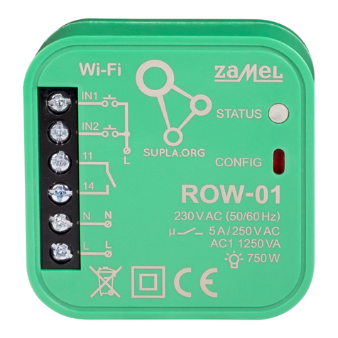
Zamel Wi-Fi supla SLW-01 User manual

Zamel

Zamel Wi-Fi supla SLW-01 User manual

Zamel Cet Ledix SLR-01 User manual

Zamel

Zamel Cet Ledix SLR-01 User manual

Zamel RTS-01A User manual

Zamel

Zamel RTS-01A User manual

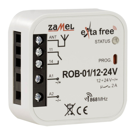
Zamel Extra Free ROB-01/12-24V User manual

Zamel

Zamel Extra Free ROB-01/12-24V User manual

Zamel Extra Free RZB-02 User manual

Zamel

Zamel Extra Free RZB-02 User manual

Zamel RTD-02 User manual

Zamel

Zamel RTD-02 User manual

Zamel Wi-Fi supla ROW-02 User manual

Zamel

Zamel Wi-Fi supla ROW-02 User manual

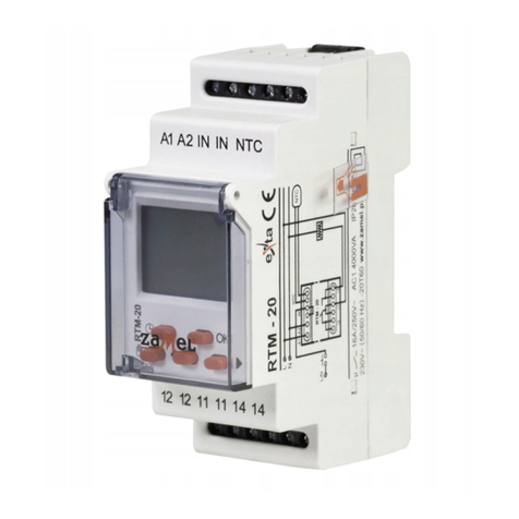
Zamel exta RTM-20 User manual

Zamel

Zamel exta RTM-20 User manual

Zamel ROB-01 User manual

Zamel

Zamel ROB-01 User manual

Zamel Exta Life EFC-01 User manual

Zamel

Zamel Exta Life EFC-01 User manual

Zamel exta free RZB-01 User manual

Zamel

Zamel exta free RZB-01 User manual

Zamel RNK-02 User manual

Zamel

Zamel RNK-02 User manual

Zamel RZB-05 User manual

Zamel

Zamel RZB-05 User manual

Zamel exta SRM-11 User manual

Zamel

Zamel exta SRM-11 User manual

Zamel supla SRW-01 User manual

Zamel

Zamel supla SRW-01 User manual

Zamel RNK-02 User manual

Zamel

Zamel RNK-02 User manual

Zamel SRP-22 User manual

Zamel

Zamel SRP-22 User manual

Zamel exta MOM-02 User manual

Zamel

Zamel exta MOM-02 User manual

Zamel RTP-01 User manual

Zamel

Zamel RTP-01 User manual

Zamel RTM - 01 User manual

Zamel

Zamel RTM - 01 User manual

Zamel RZB-03 User manual

Zamel

Zamel RZB-03 User manual

Zamel SRP-02 User manual

Zamel

Zamel SRP-02 User manual

Popular Controllers manuals by other brands

HGLRC Zeus25 AIO manual

HGLRC

HGLRC Zeus25 AIO manual

Nice PLUTO PL 4000 Instruction manual and spare parts catalogue

Nice

Nice PLUTO PL 4000 Instruction manual and spare parts catalogue

Unitronics Vision OPLC V350-35-TR20 installation guide

Unitronics

Unitronics Vision OPLC V350-35-TR20 installation guide

Tech Controllers EU-28 SIGMA user manual

Tech Controllers

Tech Controllers EU-28 SIGMA user manual

ELCOS CIM-250 Instruction and user's manual

ELCOS

ELCOS CIM-250 Instruction and user's manual

Honeywell Lyric Programming manual

Honeywell

Honeywell Lyric Programming manual

Vanderbilt ACTpro-1500 Installation and operating instructions

Vanderbilt

Vanderbilt ACTpro-1500 Installation and operating instructions

DOLD SAFEMASTER BH 5902/01MF2 operating instructions

DOLD

DOLD SAFEMASTER BH 5902/01MF2 operating instructions

Emerson Bettis G01 Series Installation, operation and maintenance manual

Emerson

Emerson Bettis G01 Series Installation, operation and maintenance manual

Rain Bird IQNCCEN Installation/configuration

Rain Bird

Rain Bird IQNCCEN Installation/configuration

ZTW BEAST PRO G2 Series user manual

ZTW

ZTW BEAST PRO G2 Series user manual

Nortel QPC757 Installation

Nortel

Nortel QPC757 Installation

ABB COMMANDER 360 user guide

ABB

ABB COMMANDER 360 user guide

Auber RDK-300B instruction manual

Auber

Auber RDK-300B instruction manual

Keytec MAGIC TOUCH DRIVER installation instructions

Keytec

Keytec MAGIC TOUCH DRIVER installation instructions

Supertech instruments CO2-2x user manual

Supertech instruments

Supertech instruments CO2-2x user manual

ICP CON I-7188XC Series user manual

ICP CON

ICP CON I-7188XC Series user manual

Instrutech VGC301 user manual

Instrutech

Instrutech VGC301 user manual

manuals.online logo
manuals.online logoBrands
  • About & Mission
  • Contact us
  • Privacy Policy
  • Terms and Conditions

Copyright 2025 Manuals.Online. All Rights Reserved.