manuals.online logo
Brands
  1. Home
  2. •
  3. Brands
  4. •
  5. Zamel
  6. •
  7. Controllers
  8. •
  9. Zamel RZB-05 User manual

Zamel RZB-05 User manual

COOPERATION AND OPERATING RANGE
* 1-channel transmitters do not cooperate with roller blind controllers.
CAUTION: The given range concerns open area - an ideal condition without any
natural or articial obstacles. If there are some obstacles between a transmit-
ter and a receiver, it is advisable to decrease the range according to: wood and
plaster: from 5 to 20 %, bricks: from 10 to 40 %, reinforced concrete: from 40 to
80 %, metal: from 90 to 100%, glass: from 10 to 20 %, Over- and underground
medium and high electrical power lines, radio and television transmitters, GSM
transmitters set close to a device system have also a negative inuence on the
range.
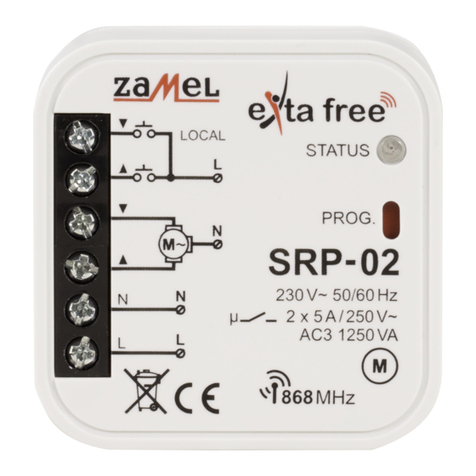
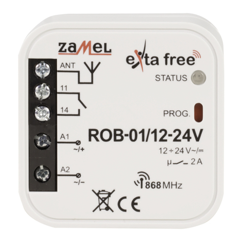
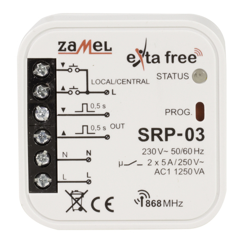
Symbol ROP-01 ROP-02 ROB-01 SRP-02 SRP-03 RWG-
01 RWL-01 ROM-01 ROM-10 RDP-01 RTN-01
RNK-02 180 m 200 m 200 m 200 m 200 m 250 m 180 m 250 m 250 m 180 m 250 m
RNK-04 180 m 200 m 200 m 200 m 200 m 250 m 180 m 250 m 250 m 180 m 250 m
P-256/8 230 m 250 m 250 m 250 m 250 m 300 m 200 m 300 m 300 m 230 m 300 m
P-257/4 (2) 180 m 200 m 200 m 200 m 200 m 250 m 180 m 250 m 250 m 180 m 250 m
RNM-10 230 m 250 m 250 m 250 m 250 m 300 m 200 m 300 m 300 m 230 m 300 m
RNP-01 160 m 180 m 180 m 180 m 180 m 200 m 160 m 200 m 200 m 160 m 200 m
RNP-02 160 m 180 m 180 m 180 m 180 m 200 m 160 m 200 m 200 m 160 m 200 m
RNL-01 160 m 180 m 180 m
lack* lack*
200 m 160 m 200 m 200 m 160 m 200 m
RTN-01 200 m 200 m 200 m 200 m 200 m 250 m 200 m 250 m 250 m 200 m 250 m
RCR-01 160 m 180 m 180 m
lack* lack*
200 m 160 m 200 m 200 m 160 m 200 m
RTI-01 160 m 180 m 180 m 180 m 180 m 200 m 160 m 200 m 200 m 160 m 200 m
RXM-01 230 m 250 m 250 m 250 m 250 m 300 m 200 m 300 m 300 m 230 m 300 m
RADIO TRANSMITTERS DELETION
Press PROG push-button of ROP-01 device for a longer time.
After 5 seconds LED red diode switches on (signal pulsates) and then it switches
off.
Release the push-button in ROP-01 - MEMORY IS DELETED.
TIME PROGRAMMING
Press PROG push-button of ROP-01 device for a longer time till LED red diode
switches on (constant signal). Next release PROG push-button. Wait (for about
5 seconds) till LED red diode switches on (rst signal pulsates, next the signal is
constant).
Press PROG push-button of ROP-01 device and then release it. LED red diode
switches off and then switches on (signal pulsates). Every LED diode pulse
equals 1 second.
After the adjusted time is nished (the number of LED red diode ashes) press
PROG push-button and then release it - TIME IS ADDED.
Maximum time is 18 hours.
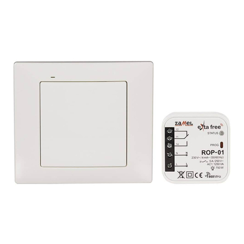
UNIVERSAL WIRELESS CONTROL SET
RZB-05
TECHNICAL DATA
P-257/2 ROP-01
Input (supply) terminals:
-L, N
Input rated voltage:
3 V (battery CR2032) 230 V~
Battery life:
3 ÷ 5 years -
Input voltage tolerance:
- -15 ÷ +10 %
Nominal frequency:
- 50 / 60 Hz
Nominal power consumption:
-0,29 W
Number of operation modes:
- 5
Number of channels:
2 1
Transmission:
radio 868,32 MHz
Transmission way: unidirectional
Coding: addressing transmission
Maximum number of transmitters:
- 32
Range: up to 250 m in the open air up to 230 m in the open air
Time adjustment:
-
1 s ÷ 18 hours (every
second)
Optical signalling: LED red diode
Relay output clamps:
-12, 11, 14
Relay contacts parameters:
-1NO/NC 5A / 250V AC AC1
1250 VA
Number of terminal clamps:
- 5
Section of connecting cables:
-up to 2,5 mm2
Ambient temperature range:
-10 ÷ +55 oC
Operating position:
free
Mounting:
-
installation cable box Ø60
mm
Casing protection degree:
IP20 (EN 60529)
Protection level:
III II
Overvoltage category:
- II
Pollution degree:
2
Surge voltage:
-1 kV (EN 61000-4-5)
Dimensi
ons: 74 x 33 x 11,5 mm 47,5 x 47,5 x 20 mm
Weig
ht: 0,020 kg 0,043 kg
Reference standard: PN-ETSI EN 300 220-1
PN-ETSI EN 300 220-2
PN-EN 60669, PN-EN
60950, PN-EN 6100
OPERATION P-257/2
After pressing the push-button the remote control sends a signal on 868,32 MHz
which controls EXTA FREE receivers. Device programming procedure (adding a
transmitter to the transmitter’s memory) is described in manual instruction of
particular EXTA FREE system receivers.
The range (up to 250 m depending on a receiver) can be changed by means of a
retransmitter or few RTN-01 retransmitters.
BATTERY CHANGE
Battery discharge status is signalled by several LED red diode ashes during
transmission time.
Remove the screws from the bottom part of the remote control.
Remove the upper cover with the silicon keyboard.
Remove the battery from the latch.
OPERATION, MOUNTING ROP-01
CONNECTION
Disconnect power supply by the phase fuse, the circuit-breaker or the switch-dis-
connector combined to the proper circuit.
Check if there is no voltage on connection cables by means of a special meas-
ure equipment.
Connect the cables with the terminals in accordance with the installing diagram.
Install ROP-01 device in installation cable box.
Switch on the power supply from the mains.
The device can operate in ve modes:
MONOSTABLE the relay operates only while pressing transmitter’s push-button.
BISTABLE (one push-button) the device changes relay status cyclically always after
pressing the same push-button.
SWITCH ON the device switches on after pressing the push-button.
SWITCH OFF the device switches off after pressing the push-button.
TIME the device switches off according to the adjusted time (tp), but it may be
switched off before adjusted time nishes. Default settings - 15 seconds.
CAUTION! Adjusted time can not be deleted.
RADIO TRANSMITTERS PROGRAMMING
MONOSTABLE mode:
Press transmitter’s push-button for a longer time.
Press PROG push-button of ROP-01 device for a longer time until LED red diode
switches on (constant signal). Next release PROG push-button.
Release transmitter’s push-button. LED red diode switches on (rst signal pul-
sates, next the signal is constant).
Press the same transmitter’s push-button and release it. LED red diode switches
on (the signal pulsates) and next it switches off - THE TRANSMITTER IS ADDED.
BISTABLE mode:
Press PROG push-button of ROP-01 device for a longer time until LED red diode
switches on (constant signal). Next release PROG push-button.
Press the transmitter’s push-button for a longer time. LED red diode switches on
(rst signal pulsates, next the signal is constant).
Release transmitter’s push-button. LED red diode switches on (the signal
pulsates), next the LED red diode switches off - it means the TRANSMITTER IS
ADDED.
SWITCH ON/SWITCH OFF mode (two push-buttons):
Press PROG push-button of ROP-01 device for a longer time until LED red diode
switches on (constant signal). Next release PROG push-button.
Press and release transmitter’s pushbutton. LED red diode switches on (rst signal
pulsates, next the signal is constant).
Press and release the same transmitter’s push-button. LED red diode switches on
(the signal pulsates) and next it switches off - THE TRANSMITTER IS ADDED.
TIME mode (one push-button)
Press PROG push-button of ROP-01 device for a longer time till LED red diode
switches on (constant signal). Next release PROG push-button.
Press and release transmitter’s pushbutton. LED red diode switches on (the signal
pulsates, next the signal is constant).
Press and release the same transmitter’s push-button. LED red diode switches on
(the signal pulsates) and next it switches off - THE TRANSMITTER IS ADDED.
An exemplary programming procedure with the use of P-257/2 remote controller.
The procedure for the rest of radio EXTA FREE transmitters is analogous. CAUTION:
Every transmitter can cooperate with ROP-01 in a different mode, depending on
how they were added to the device. One transmitter can be added during one
programming cycle. Full memory is signalled with pulsating LED red diode.
Mount a new battery. Watch battery polarisation marked on the latch. Wrong
battery mounting may cause device damage.
Place back the top cover with the keyboard and tighten the screws.
CAUTION: While changing the battery, it is suggested to press any of the but-
tons for about 5 seconds before putting it into a latch. Next press transmis-
sion button several times to check its operation. If the transmitter does not
work properly repeat the battery change procedure.
Other manuals for RZB-05

2

This manual suits for next models

2

Other Zamel Controllers manuals

Zamel Cet LediX SLR-11P User manual

Zamel

Zamel Cet LediX SLR-11P User manual

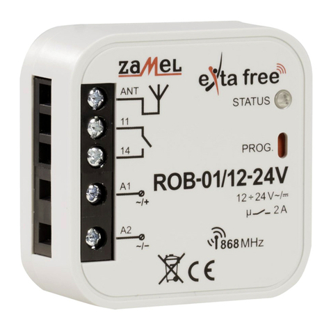
Zamel Extra Free ROB-01/12-24V User manual

Zamel

Zamel Extra Free ROB-01/12-24V User manual

Zamel ROW-01 User manual

Zamel

Zamel ROW-01 User manual

Zamel RNK-02 User manual

Zamel

Zamel RNK-02 User manual

Zamel Wi-Fi supla SLW-01 User manual

Zamel

Zamel Wi-Fi supla SLW-01 User manual

Zamel NC60 User manual

Zamel

Zamel NC60 User manual

Zamel RNK-02 User manual

Zamel

Zamel RNK-02 User manual

Zamel Exta Life EFC-01 User manual

Zamel

Zamel Exta Life EFC-01 User manual

Zamel ledix SLR-13 User manual

Zamel

Zamel ledix SLR-13 User manual

Zamel exita ZIM-12/08 User manual

Zamel

Zamel exita ZIM-12/08 User manual

Zamel SRP-02 User manual

Zamel

Zamel SRP-02 User manual

Zamel supla SRW-01 User manual

Zamel

Zamel supla SRW-01 User manual

Zamel exta SRP-05 User manual

Zamel

Zamel exta SRP-05 User manual

Zamel RZB-04 User manual

Zamel

Zamel RZB-04 User manual

Zamel RTD-02 User manual

Zamel

Zamel RTD-02 User manual

Zamel Supla SLW-02 User manual

Zamel

Zamel Supla SLW-02 User manual

Zamel RTP-01 User manual

Zamel

Zamel RTP-01 User manual

Zamel Extra Free ROB-01/12-24V User manual

Zamel

Zamel Extra Free ROB-01/12-24V User manual

Zamel GRM-10 User manual

Zamel

Zamel GRM-10 User manual

Zamel Exta Free EFC-02 Mini User manual

Zamel

Zamel Exta Free EFC-02 Mini User manual

Zamel Extra Free RZB-02 User manual

Zamel

Zamel Extra Free RZB-02 User manual

Zamel exta ZIM-12/25 User manual

Zamel

Zamel exta ZIM-12/25 User manual

Zamel SRP-03 User manual

Zamel

Zamel SRP-03 User manual

Zamel exta life ROB-21 User manual

Zamel

Zamel exta life ROB-21 User manual

Popular Controllers manuals by other brands

INSTEON 2477SA1 quick start guide

INSTEON

INSTEON 2477SA1 quick start guide

Poniie TC-DN2 user manual

Poniie

Poniie TC-DN2 user manual

Extron electronics MLC Plus 84 EU Setup guide

Extron electronics

Extron electronics MLC Plus 84 EU Setup guide

Farfisa 2281Q manual

Farfisa

Farfisa 2281Q manual

Pilz PNOZ mo3p operating manual

Pilz

Pilz PNOZ mo3p operating manual

Hanna Instruments pH 500 Series instruction manual

Hanna Instruments

Hanna Instruments pH 500 Series instruction manual

Elmes Electronic STM manual

Elmes Electronic

Elmes Electronic STM manual

Jobsite V-10-50IM Installation & user guide

Jobsite

Jobsite V-10-50IM Installation & user guide

Micatrone MRP-2000 Operating and installation guide

Micatrone

Micatrone MRP-2000 Operating and installation guide

Siemens SIMATIC ET 200SP manual

Siemens

Siemens SIMATIC ET 200SP manual

Seada DS2-9H user guide

Seada

Seada DS2-9H user guide

GEA VARIVENT operating instructions

GEA

GEA VARIVENT operating instructions

Deep Sea Electronics Plc DSE701 MKII Installation instructions and instructions for use

Deep Sea Electronics Plc

Deep Sea Electronics Plc DSE701 MKII Installation instructions and instructions for use

Lenze L-force CS Series operating instructions

Lenze

Lenze L-force CS Series operating instructions

Mains MV4k/1 instructions

Mains

Mains MV4k/1 instructions

Dell iDRAC Release notes

Dell

Dell iDRAC Release notes

Fuji Electric FALDIC-a user manual

Fuji Electric

Fuji Electric FALDIC-a user manual

Evenheat Set-Pro operating manual

Evenheat

Evenheat Set-Pro operating manual

manuals.online logo
manuals.online logoBrands
  • About & Mission
  • Contact us
  • Privacy Policy
  • Terms and Conditions

Copyright 2025 Manuals.Online. All Rights Reserved.