manuals.online logo
Brands
  1. Home
  2. •
  3. Brands
  4. •
  5. 3One data
  6. •
  7. Switch
  8. •
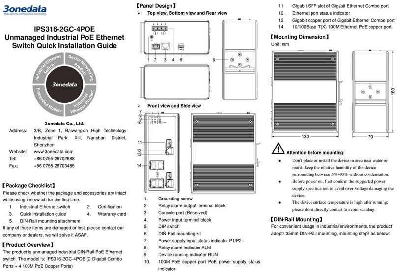
  9. 3One data IES3000 Series User manual

3One data IES3000 Series User manual

IES3000 Series
Industrial Managed Bypass Ethernet
Switch
Quick Installation Guide
3onedata Co., Ltd.
【Package Checklist】
Please check whether the package and accessories are intact
while using the switch for the first time
1.
Switch
2.
Quick installation guide
3.
Installation CD
4.
Rackmount attachment
5.
Certification
6.
Warranty card
7.
Power cord
If any of these items are damaged or lost, please contact our
company or dealers, we will solve it ASAP.
【Product Overview】
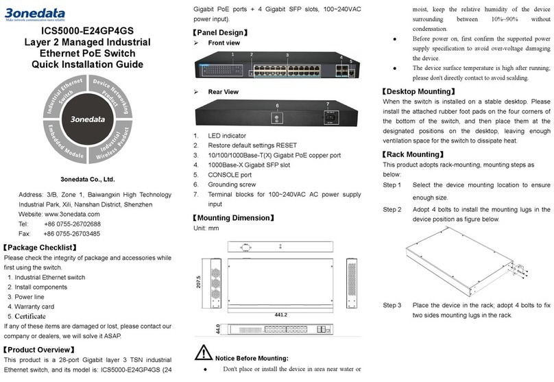
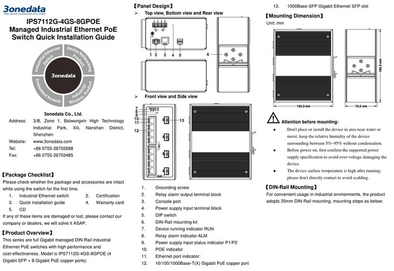
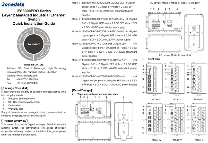
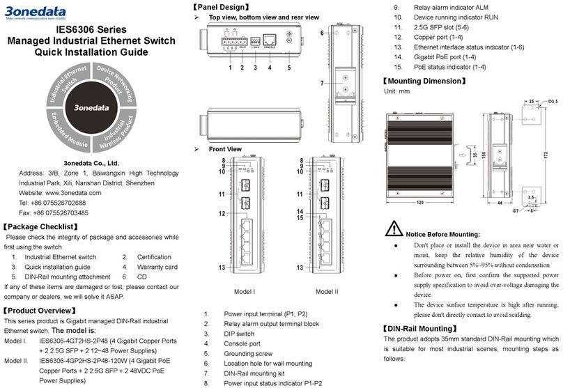
This product is industrial rack-mounted full gigabit managed
Bypass Ethernet switch. The models are:
Model I IES3000-8GP4GS-2BP-2P48-240W (8 Gigabit
PoE copper ports + 4 Gigabit SFP + 2 Bypass + 2
48VDC power supplies + 240W power
consumption)
Model II IES3000-8GT4GS-2BP-P48P220 (8 Gigabit
copper ports + 4 Gigabit SFP + 2 Bypass + 1
48VDC power supply + 1 220VAC power supply)
Model III IES3000-8GT4GS-2BP-2P48 (8 Gigabit copper
ports + 4 Gigabit SFP + 2 Bypass + 2 48VDC
power supplies)
Model IV IES3000-8GT4GS-2BP-2P220 (8 Gigabit copper
ports + 4 Gigabit SFP + 2 Bypass + 2 220VAC
power supplies)
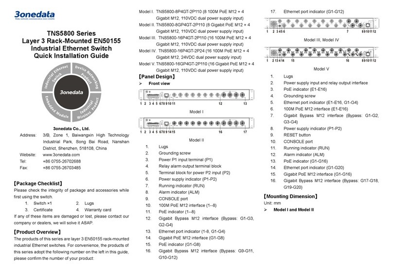
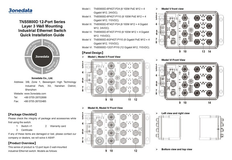
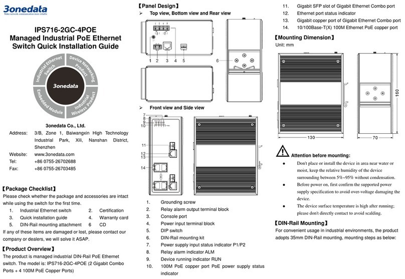
【Panel Design】
Front view
Model I
Model II
Model III
Model IV
Rear view
Left view
Right view
Top view
1. Power supply indicator
2. Alarm indicator
3. Running indicator
4. CONSOLE port
5. Gigabit copper port
6. Port indicator
7. PoE indicator
8. Gigabit SFP slot
9. DIP switch
10. Flange interface
11. Relay input terminal
12. DC power supply
13. AC power supply
【Mounting Dimension】
Address:
3/B, Zone 1, Baiwangxin High Technology
Industrial Park, Xili, Nanshan District,
Shenzhen
Website:
www.3onedata.com
Tel:
+86 0755-26702688
Fax:
+86 0755-26703485
Unit: mm
Attention before mounting:
Don't place or install the device in area near water or
moist, keep the relative humidity of the device
surrounding between 5%~95% without condensation.
Before power on, first confirm the supported power
supply specification to avoid over-voltage damaging the
device.
The device surface temperature is high after running;
please don't directly contact to avoid scalding.
【Mounting the Device】
Step 1 Select the device mounting location to ensure
enough size.
Step 2 Use 4 screws to mount the mounting lugs to the
device as shown below.
Step 3 Place the device on the rack surface plate; adopt 4
screws to mount the right and left mounting lugs on
the rack.
Step 4 Check and confirm that the product is mounted
firmly on the rack, mounting ends
【Dismounting the Device】
Step 1 Device powers off.
Step 2 Unscrew the fixed mounting lug screw on the rack.
Step 3 Remove the device from rack, disassembling ends.
Note before power on:
Power ON operation: first connect power line to the
connection terminal of device power supply, then power
on.
The “—” of AC power supply switch means power-on
state; and “O” means power-off state.
Power OFF operation: first unpin the power plug, then
remove the power line, please note the operation order
above.
【Power Supply Connection】
2 AC power supplies
The Model IV of this series provides 2 AC power
supplies, two power supply systems inside the
device, one outlet outside. When one power supply
fails, it can switch to another one automatically and
immediately to ensure device’s normal power supply. Power
supply input: 220VAC (100~240VAC)
1 DC power supply + 1 AC power supply
The Model II of this series provides 1 DC power supply and 1
AC power supply:
Power
supply type
Power supply
Schematic
Power supply range
DC
48VDC(12~48VDC)
AC
220VAC(100~240VAC)
2 DC power supplies
The Model I and Model III of this
series provide 1 6-pin 5.08mm pitch
input DC terminal. The power supply
occupies 4 pins and provides 2
independent power supply systems, PWR1 and PWR2. When
one power supply fails, it can switch to another one
automatically and immediately to ensure device’s normal
power supply. Power supply input of Model I: 48VDC, power
supply range of Model III: 48VDC (12~48VDC).
【Relay Connection】
Relay terminal is a set of normally open contacts of device’s
alarm relay. It is in open circuit status when it has no alarm,
close circuit when it has any alarm. For example: when
powered off, it’s in close circuit and sending out alarm. This
switch supports 1 relay alarm information output, output power
supply alarm or network anomaly alarm. It can attach external
warning light, alarm buzzer or other switch states acquisition
device to warn operators in time when there has an alarm.
【Flange Interface Connection】
This device provides Bypass function. As shown below, A2
and B2 ends that on the left side represent internal terminal
blocks of flange interface, A1 and B1 ends that on the right
side of dotted line represent external terminal blocks of flange
interface.
Status
Description
Status
Description
When powered on,
TX, RX at A2 end
connect to RX, TX at A1
side separately,
TX, RX at B2 end
connect to RX, TX at B1
side separately.
When powered off,
TX, RX at A1 side
connects to RX, TX at
B1 side
Bypass function
According to the specification of SFP optical module, the
usage of fiber port Bypass is as follows:
When SFP optical module is single-mode double-fiber, 1 set
of Bypass function is supported. Connection method is
shown below.
When SFP optical module is sing-mode single-fiber, 2 sets
of Bypass function are supported. The solid line and dotted
line each presents 1 set of Bypass connection method as
shown below:
When the switch is normally powered on and operating, it can
communicate with other devices normally. When it’s powered
off, fiber port A and B can connect to each other without
interfering other devices’normal communication.
【DIP Switch Setting】
This device provides 4-bit DIP switch for function
setting. “ON” is enable valid port. Please power
off and power on after changing the status of DIP
switch.
The definitions of DIP switches are as follows:
1.restore factory setting
2.reserved
3.reserved
4.reserved
【Console Port Connection】
This device provides an application debugging port based on
RS232 serial port which could connect to PC for device’s CLI
command management. It adopts RJ45 port, and its pin
definitions are as follows:
Pin
2
3
5
Definition
TXD
RXD
GND
【Checking LED Indicator】
The device provides LED indicators to monitor device’s
operation status and comprehensively simplify
troubleshooting process. The detailed status of each LED is
described in the table as below:
LED
Status
Description
PWR1
ON
Power supply P1 is
connected normally
OFF
Power supply P1 is
disconnected or running
abnormally
PWR2
ON
Power supply P2 is
connected normally
OFF
Power supply P2 is
disconnected or running
abnormally
ALM
ON
Power supply or port link is
giving an alarm
OFF
Power supply or port link isn’t
giving any alarm
RUN
ON
Device is powered on or
running abnormally
OFF
Device is powered off or
running abnormally
Blinking
Blinking 1 time/s, device
operates normally
Link/Act
(1~12)
ON
Ethernet port has established
an active network connection
Blinking
Ethernet port is in an active
network state
OFF
Ethernet port hasn’t
established an active network
connection
PoE
(G1-G12)
(only for
PoE
product)
ON
PoE port is powering other
devices normally
OFF
PoE port is not powering
other devices or
disconnected
【Specification】
Panel
Gigabit SFP
1000Base-SFP, SFP slot
Gigabit copper port
10/100/1000Base-T(X)
self-adaptive RJ45 port, full/half
self-adaption, MDI/MDI-X
self-adaption
PoE (Only for PoE
product)
The maximum power of PoE port:
30W
PoE power supply pin: V+, V+, V-
and V- correspond to Pin 1, 2, 3
and 6
Flange interface
2*4LC-LC, single mode fiber,
support Bypass
Console port
CLI command management
port(RS-232), RJ45
Alarm port
2-pin 5.08mm pitch terminal blocks
or 4-pin 5.08mm pitch terminal
blocks, support 1 relay alarm
output, current carrying capacity is
0.3A/125VAC or 1A/30VDC
Indicator
Running indicator, port indicator,
power supply indicator, alarm
indicator
Switch property
Backplane bandwidth
24G
Packet buffer size
4Mbit
MAC address
8K
Power supply
Input power supply
AC power supply product:
220VAC(100~240VAC)
DC power supply product:
48VDC(12~48VDC);
PoE product: 48VDC
Power consumption
Model IV
No-load: 5.9W@220VAC
Full-load: 11.6W@220VAC
Operating
environment
Operating temperature
-40~75℃
Storage temperature
-40~85℃
Operating humidity
5%~95% (no condensation)
Protection grade
IP40 (mental shell)

This manual suits for next models

4

Other 3One data Switch manuals

3One data PS5010G-2GS-8PoE User manual

3One data

3One data PS5010G-2GS-8PoE User manual

3One data IES6100PN-8T-2LV User manual

3One data

3One data IES6100PN-8T-2LV User manual

3One data ES209G-1GF User manual

3One data

3One data ES209G-1GF User manual

3One data IES2005-5T-P48 User manual

3One data

3One data IES2005-5T-P48 User manual

3One data IES7110 3GS Series User manual

3One data

3One data IES7110 3GS Series User manual

3One data IPS7110-2GC-8POE User manual

3One data

3One data IPS7110-2GC-8POE User manual

3One data TNS5500 Series User manual

3One data

3One data TNS5500 Series User manual

3One data IES5028 Series User manual

3One data

3One data IES5028 Series User manual

3One data IES206G-2GS User manual

3One data

3One data IES206G-2GS User manual

3One data IES1024 Series User manual

3One data

3One data IES1024 Series User manual

3One data IES6300-8GHP2GS2HS-2P48-360W User manual

3One data

3One data IES6300-8GHP2GS2HS-2P48-360W User manual

3One data TNS5800D Series User manual

3One data

3One data TNS5800D Series User manual
3One data IES7120-4GS Series User manual

3One data

3One data IES7120-4GS Series User manual

3One data IES6316-8GT8GS-2P48 User manual

3One data

3One data IES6316-8GT8GS-2P48 User manual

3One data ICS5400PTP-12GT12GS4XS User manual

3One data

3One data ICS5400PTP-12GT12GS4XS User manual

3One data ICS5000-E24GP4GS User manual

3One data

3One data ICS5000-E24GP4GS User manual

3One data ICS5530 Series User manual

3One data

3One data ICS5530 Series User manual

3One data TNS5500D Series User manual

3One data

3One data TNS5500D Series User manual

3One data IES5028G-4GS-8GC User manual

3One data

3One data IES5028G-4GS-8GC User manual

3One data ICS6420 Series User manual

3One data

3One data ICS6420 Series User manual

3One data IES615-2DI Series User manual
3One data

3One data IES615-2DI Series User manual

3One data TNS5800D User manual

3One data

3One data TNS5800D User manual

3One data IES206 Series User manual

3One data

3One data IES206 Series User manual

3One data IES6300 Series User manual

3One data

3One data IES6300 Series User manual

Popular Switch manuals by other brands

Generac Power Systems GTS "W" owner's manual

Generac Power Systems

Generac Power Systems GTS "W" owner's manual

Juniper EX8200 Series Installing and connecting

Juniper

Juniper EX8200 Series Installing and connecting

RFL Electronics RFL 9660 instruction manual

RFL Electronics

RFL Electronics RFL 9660 instruction manual

Blankom WLANIOS 5161.01 operating instructions

Blankom

Blankom WLANIOS 5161.01 operating instructions

Daxten SCOUTUTP - brochure

Daxten

Daxten SCOUTUTP - brochure

IFM AL3100 operating instructions

IFM

IFM AL3100 operating instructions

Dimplex KX03001 Installation and operating instructions

Dimplex

Dimplex KX03001 Installation and operating instructions

Edge-Core ES3628EA user manual

Edge-Core

Edge-Core ES3628EA user manual

ZyXEL Communications XS3800-28 user guide

ZyXEL Communications

ZyXEL Communications XS3800-28 user guide

Perreaux TS2 datasheet

Perreaux

Perreaux TS2 datasheet

StarTech.com 5G7AINDRM-USB-A-HUB quick start guide

StarTech.com

StarTech.com 5G7AINDRM-USB-A-HUB quick start guide

Avaya Cajun P333T user guide

Avaya

Avaya Cajun P333T user guide

Altinex MX2100AV user guide

Altinex

Altinex MX2100AV user guide

TP-Link tapo 7106509958 quick start guide

TP-Link

TP-Link tapo 7106509958 quick start guide

StarTech.com IES101G2SFPW quick start guide

StarTech.com

StarTech.com IES101G2SFPW quick start guide

Sandvine PTS 8210 installation guide

Sandvine

Sandvine PTS 8210 installation guide

CIS CRS112-8P product manual

CIS

CIS CRS112-8P product manual

Ei Electronics Ei1529RC instructions

Ei Electronics

Ei Electronics Ei1529RC instructions

manuals.online logo
manuals.online logoBrands
  • About & Mission
  • Contact us
  • Privacy Policy
  • Terms and Conditions

Copyright 2025 Manuals.Online. All Rights Reserved.