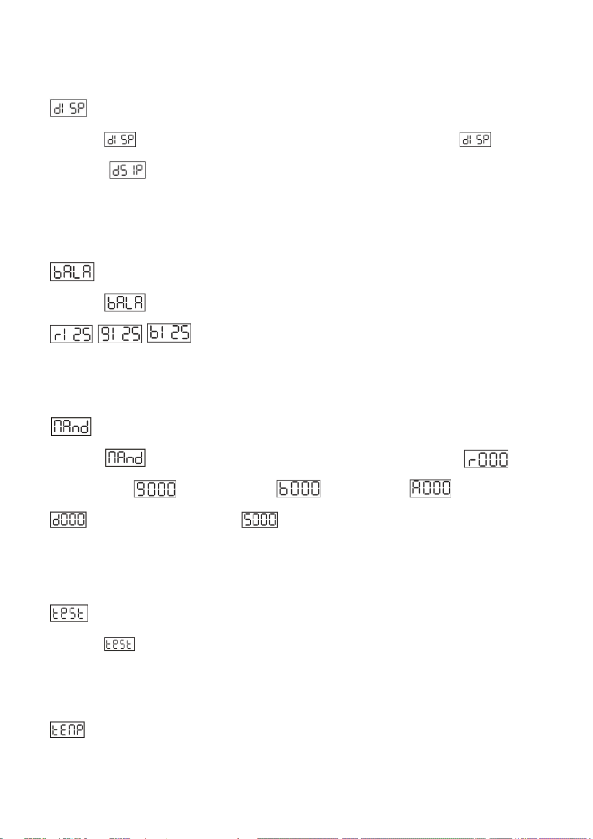
ACME STAGE PAR 100 COLOUR IP User manual

STAGE PAR 100 COLOUR IP

1D
Menu
1. Safety Instructions............................................................................................................................1
2. Technical Specifications....................................................................................................................2
3. Installation and Connection .............................................................................................................3
4. How to set the unit...........................................................................................................................4
4.1 Rear Panel.......................................................................................................................................4
4.2 Main Function.................................................................................................................................5
5. How to control the unit ....................................................................................................................9
6. DMX512 configuration ................................................................................................................. 10`
7. DMX512 Connection.......................................................................................................................11
8.Troubleshooting...............................................................................................................................12
9. Fixture Cleaning..............................................................................................................................13

2D
1. Safety Instructions
WARNING
Please keep this User Manual for future consultation. If you sell the fixture to another user, be sure
that they also receive this instruction booklet.
Please unpack and check carefully there is no transportation damage before using the fixture.
Please disconnect main power before servicing and maintenance.
The unit must be installed in a location with adequate ventilation, at least 50cm from adjacent
surfaces. Be sure that no ventilation slots are blocked.
The maximum ambient temperature is Ta: 40℃. DO NOT operate it where the temperature is higher
than this.
DO NOT connect the device to any dimmer pack.
The housing must be replaced if they are visibly damaged.
Unit surface temperature may reach up to 60℃. Don’t touch the housing bare-hand during its
operation. Turn off the power and allow about 15 minutes for the unit to cool down before replacing
or serving.
Stop using the fixture immediately and disconnect the power source for inspection if the fixture fails.
Do not repair it by yourself if you are non-professional technician. For any help, please contact your
nearest authorized sales or technical center.
2. Technical Specifications
4/6/7/8 channel Mode;
Dimmer, Strobe;
Please read the instruction carefully which includes important
information about the installation, usage and maintenance.

3D
Ideal for Professional stages, Concerts, clubs, discotheques, Mobile DJs, etc.
Input Voltage:AC100V~240V,50/60Hz
Total Power consumption:
Beam Angle:
IP Grade:
LED Sources:
110W
7°/11.5°/16°/20.5°/25°
IP X4
PUMG-120F4A-ND4P
Dimension/Weight:
534 x 281 x 224mm, 4.5Kg
21"x11"x8.8"in, 9.9lbs
3. Installation and Connection
The unit should be mounted via its screw holes on the bracket. Always ensure that the unit is firmly fixed
to avoid vibration and slipping while operating. Always ensure that the structure to which you are
attaching the unit is secure and is able to support a weight of 10 times of the unit’s weight. Also always
use a safety cable that can hold 12 times of the weight of the unit when installing the fixture.
The equipment must be fixed by professionals. And it must be fixed at a place where is out of the touch
of people and has no one pass by or under it. The unit should be mounted in the height of 0 to 30m.

4D
4. How to set the unit
4.1 Rear Panel
○
1Display: Show the various menus and the selected functions;
○
2 LED indicator:
POWER On Power On
DMX On DMX input present
○
3 Button:
MENU
To select the programming functions
DOWN
To go forward in the selected functions
UP
To go backward in the selected functions
ENTER
To confirm the selected functions
○
4 Mains input/output::Use Powercon true one mains connection.
○
5DMX input/output:
For DMX512 link, use 3/5-pin XLR plug cable to input DMX signal, and to link the next unit.
The beam angle can be adjusted manually, which is 7°/11.5°/16°/2 0.5°/2 5 °.

5D
4.2 Main Function
To select any functions, press MENU button until the required one is shown on the display. Select the
function by ENTER button. Use DOWN and UP button to change the mode. Once the required mode has
been selected, press ENTER button to setup or it will return to the main functions without any change
after idling 8 seconds automatically. Back to the functions without any change press MENU button. The
main functions are shown below:

6D
DMX 512 Address Setting
Select the , press the ENTER button and the display will blink. Use the DOWN and UP button to
change the DMX 512 address(001-512). Once the address has been selected, press the ENTER button to
setup or exit menu mode without any change after 8 seconds automatically. Back to the previous
functions without any change press the MENU button.
Channel Mode
Select the , press the ENTER button. Use the DOWN and UP button to select the channel mode
(4CH/ 6CH/7CH/8CH). Once the address has been selected, press the ENTER button to setup or exit
menu mode without any change after 8 seconds automatically. Back to the previous functions without
any change press the MENU button.
Dimmer Mode

7D
Select the , press the ENTER button. Use the DOWN and UP button to select (Dimmer
Mode 1)… (Dimmer Mode 4). Once selected, press the ENTER button to setup or exit menu
mode without any change after 8 seconds. Back to the functions without any change press the MENU
button again.
Dimmer mode 1 Dimmer mode 2 Dimmer mode 3 Dimmer mode 4
Optically Linear Square Law Inverse-Square Law S-Curve
Mode 1(Optically Linear): The increase in light intensity appears to be linear as DMX value is increased.
Mode 2(Square Law): Light intensity control is finer at low levels and coarser at high levels.
Mode 3(Inverse Square Law): Light intensity control is coarser at low levels and finger at high levels.
Mode 4(S-cure): Light intensity control is finger at low levels and high levels and coarser at medium
levels.
Dimmer Speed
Select the , press the ENTER button. Use the DOWN and UP button to select (Fast) or
(Smooth). Once selected, press the ENTER button to setup or exit menu mode without any
change after 8 seconds. Back to the functions without any change press the MENU button again.
DMX State
Select the , press the ENTER button. Use the DOWN and UP button to select
(Blackout) or (Hold the last state) . Once selected, press the ENTER button to setup or exit
menu mode without any change after 8 seconds. Back to the functions without any change press the
MENU button again.

8D
Display Inverse
Select the , press the ENTER button. Use the DOWN and UP button to select (Display
Normal) or (Display Inverse). Once selected, press the ENTER button to setup or exit menu
mode without any change after 8 seconds automatically. Back to the functions without any change press
the MENU button again.
White Balance
Select the , press the ENTER button. use the DOWN and UP button to select
/ / , You can choose values between 125-255,and press the ENTER button to
setup or automatically exit menu mode without any change after 8 seconds. To go back to the functions
without any change press the MENU button
Manual mode
Select the , press the ENTER button. Use the DOWN and UP button to select
RED(R000-R255)/ GREEN(G000-G255)/ BLUE(B000-B255)/ AMBER(A000-A255)/
the brightness (d000-d255)or strobe(S000-S255). Once selected, press the ENTER
button to setup or exit menu mode without any change after 8 seconds automatically. Back to the
functions without any change press the MENU button again.
Auto Test
Select the , press the ENTER button and the unit will run self-test by built-in program. To go back
to the functions press the MENU button again. Hold and press the MENU button about one second or
wait for one minute to exit the menu mode.
Temperature Display

9D
Select the , press ENTER button and the display will show the temperature,To go back to the
functions press the MENU button.
Fixture Hour
Select the , press ENTER button and the display will show the number of working hours of the
unit. To go back to the functions press the MENU button.
Software Version
Select the , press ENTER button and the display will show the version of software of the unit.
To go back to the functions press the MENU button.
RDM function
Select the DMX start menu to change the DMX 512 address(001-512)
Select the manufac tuner menu to display the lamp brand acme.
Select the device model description menu to select the lamp model STAGE PAR 100 COLOUR IP.
Select the DMX performance menu to set the lamp channel 4channel / 6channel / 7channel / 8channel.
Select the device label menu to change the lamp model. The initial model is STAGE PAR 100 COLOUR IP..
Select the identity device menu, and the off / on option will appear. When you select on, the strobe will
appear on the lamp, and select off to turn off the strobe.
Select the device hours menu to display the lamp usage time.
Select the DMX personal menu to display the channel mode used by the luminaire.
Select reset device menu, and the warm / cold option will appear. When warm is selected, the lamp will
restart, and exit when cold is selected.
Select the software menu and the lamp program version number will be displayed.
Select the LED menu to display the LED temperature of the lamp.
5. How to control the unit
1.By DMX controller;
No need to turn the unit off when you change the DMX address, as new DMX address setting will be
affected at once. Turn on the unit, under the DMX signal , the LED will display the saved channel address
(001-512).

10D
6. DMX512 configuration
Channel Mode:

11D
7. DMX512 Connection
Mode connection:

12D
1. Connect the fixture together in a “daisy chain” by XLR plug cable from the output of the fixture to
the input of the next fixture. The cable cannot be branched or split to a “Y” cable. Inadequate or
damaged cables, soldered joints or corroded connectors can easily distort the signal and shut down
the system
2. The DMX output and input connectors are pass-through to maintain the DMX circuit when one of
the units’ power is disconnected.
3. At last fixture, the DMX cable has to be terminated with a terminator to reduce signal errors. Solder
a 120-ohm 1/4W resistor between pin 2(DMX-) and pin 3(DMX+) into a 3-pin XLR-plug and plug it in
the DMX-output of the last fixture.
4. Each lighting fixture needs to have an address set to receive the data sent by the controller. The
address number is between 0-511 (usually 0 & 1 are equal to 1).
5. 3/5 pin XLR connectors:.
3 pin XLR: Pin 1: GND, Pin 2: Negative signal (-), Pin 3: Positive signal (+), Pin 4: Blank, Pin 5: Blank
8.Troubleshooting
Following are a few common problems that may occur during operation. Here are some suggestions for
easy troubleshooting:
A. The fixture does not work, no light
1. Check the connection of power and main fuse.
2. Measure the mains voltage on the main connector.
B. Not responding to DMX controller
1. DMX LED should be on. If not, check DMX connectors, cables to see if link properly.
2. If the DMX LED is on and no response to the channel, check the address settings and DMX polarity.
3. If you have intermittent DMX signal problems, check the pins on connectors or on PCB of the fixture
or the previous one.
4. Try to use another DMX controller.
5. Check if the DMX cables run near or run alongside to high voltage cables that may cause damage or

13D
interference to DMX interface circuit.
Error code
Err1
Temperature Fault
Err2
LED Fan Fault
Err3
Main board and sub board communication Fault
9. Fixture Cleaning
The cleaning of internal must be carried out periodically to optimize light output. Cleaning frequency
depends on the environment in which the fixture operates: damp, smoky or particularly dirty
surrounding can cause greater accumulation of dirt on the fixture’s optics.
Clean with soft cloth using normal glass cleaning fluid.
Always dry the parts carefully.
Clean the external optics at least every 20 days. Clean the internal optics at least every 30/60 days.

14D

15D
Declaration of Conformity
We declare that our products (lighting equipments) comply with the following
specification and bears CE mark in accordance with the provision of the
Electromagnetic Compatibility (EMC) Directive 2004/108/EC.
EN55103-1: 2009 ; EN55103-2: 2009;
EN61000-3-2: 2006 + A1:2009 + A2:2009; EN61000-3-3: 2008.
&
Harmonized Standard
EN 60598-1:2008 + All:2009; EN 60598-2-17:1989 + A2:1991;
EN 62471:2008; EN 62493: 2010
Safety of household and similar electrical appliances
Part 1: General requirements
Table of contents
Other ACME Lighting Equipment manuals

ACME
ACME IL-2420 II User manual

ACME
ACME MP-12FC User manual

ACME
ACME Warrior Scan 50 LED-SC50C User manual

ACME
ACME CA-DC6S User manual

ACME
ACME Neozone User manual

ACME
ACME XP-5000WZ User manual

ACME
ACME GLAMOUR 700Z RGBY User manual

ACME
ACME DOT User manual

ACME
ACME SAMURAI SCAN 50 User manual

ACME
ACME Splendor 220 II User manual

ACME
ACME STORM User manual

ACME
ACME Beluga User manual

ACME
ACME Solaris User manual

ACME
ACME GLORV FRAMING XP-5000SZF User manual

ACME
ACME ENERGY HYBRID X-400 BSW User manual

ACME
ACME Libre User manual

ACME
ACME Inferno User manual

ACME
ACME BIG BANG User manual

ACME
ACME LS-1005 User manual

ACME
ACME Pageant CM-200Z User manual