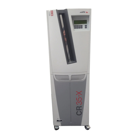
AGFA Classic E.O.S. Technical manual

Installation Planning
printed in Germany 02 / 2004
Order No.: DD+DIS303.03E
*1WACPK1*
1 piece WACPK MA 1
Classic E.O.S.
Type 5270/100
Classic E.O.S. CL
Type 5270/105
INSTALLATION PLANNING and
Technical Data
Internal Version 6
5270_10000_02.CDR
The Installation Planning Instructions can also be ordered separately.
Order number: DD+DIS303.03E
Agfa Group Confidential

Caution:
This system uses mains voltage. Please observe the pertinent safety
instructions.
These instructions describe adjustments and routines,
which must only be performed by qualified technical personnel.
Note:
Electrical repairs and connections must only be made by certified electricians.
Mechanical repairs and connections must only be made by certified
technicians.
CE Declaration:
According to the medical directives the CE Declaration
(CE Conformity) becomes void if the product is modified without permission of
the manufacturer!
This applies to all parts, not only the safety devices!
We reserve the right to change data and characteristics in the light of
technical progress.

DD+DIS303.03E Installation Planning
Edition 6, Revision 0 Classic E.O.S. / Classic E.O.S. CL Chapter 14 / I
(Type 5270 / 100 / 105)
Chapter 14
Contents
1Safety............................................................................. 1
2Scope of Delivery and Accessories............................ 3
2.1 Classic E.O.S. Type 5270/100..............................................3
2.2 Classic E.O.S. CL Type 5270/105 ........................................3
2.3 Peripheral equipment ...........................................................4
2.4 Exhaust connection through the floor ................................4
3System Overview.......................................................... 5
3.1 Classic E.O.S. Type 5270/100..............................................5
3.2 Classic E.O.S. CL Type 5270/105 ........................................6
4Machine Dimensions.................................................... 7
4.1 Classic E.O.S. Type 5270/100..............................................7
4.2 Classic E.O.S. CL Type 5270/105 ........................................8
5Transport path .............................................................. 9
6Access for Repair and Maintenance......................... 10
6.1 Classic E.O.S. Type 5270/100............................................10
6.2 Classic E.O.S. CL Type 5270/105 ......................................11
7Daylight / Darkroom Installation
(only Classic E.O.S. Type 5270/100) ......................... 12
7.1 Machine in the daylight, film feed in the darkroom,
light seal at the darkroom feed table.................................12
7.1.1 Installation at the wall opening..............................................12
7.1.2 Installation with light tight wall...............................................13
7.2 Machine in the darkroom, film exit in the daylight,
light seal at the dryer with light tight wall.........................14
7.2.1 Installation at the wall opening with light tight wall.................14
7.3 Light tight wall ....................................................................15
8Installation .................................................................. 16
8.1 Hoses and installation material .........................................16
8.2 Supply and disposal through the lower front panel
(only Classic E.O.S. Type 5270/100) ..................................17

Installation Planning DD+DIS303.03E
Chapter 14 / II Classic E.O.S. / Classic E.O.S. CL Edition 6, Revision 0
(Type 5270 / 100 / 105)
8.2.1 Instructions for breaking out the openings............................ 17
8.2.2 Required openings for standard installations........................ 17
8.2.3 Installing the developer / fixer supply hoses ......................... 18
8.2.4 Installing the disposal hoses ................................................ 19
8.3 Supply and disposal through the floor............................. 20
8.3.1 Installing the disposal hoses ................................................ 21
8.4 Replenisher tanks for developer and fixer ....................... 22
8.5 Disposal tanks.................................................................... 23
8.6 Water connection............................................................... 24
8.6.1 Wall / machine connection at a water pressure of 2 – 6 bar . 25
8.6.2 Wall / machine connection at a water pressure > 6 bar ........ 26
8.6.3 Overview of adaptation parts for water installations:............. 27
8.7 Exhaust connection ........................................................... 29
8.7.1 Exhaust connection through lower front panel
(only Type 5270/100) ........................................................... 29
8.7.2 Exhaust connection through the floor ................................... 30
8.8 Electrical connection of the machine ............................... 31
9Technical Data .............................................................33
9.1 Electrical data..................................................................... 33
9.2 Ambient and climatic conditions ...................................... 33
9.3 Transport and storage conditions .................................... 34
10 Machine Specifications...............................................35
10.1 Type overview .................................................................... 35
10.2 Film types ........................................................................... 35
10.3 Film formats ....................................................................... 35
10.4 Functional data................................................................... 36
11 Dimensions and Weights............................................37
11.1 Classic E.O.S. Type 5270/100 ........................................... 37
11.2 Classic E.O.S. CL Type 5270/105 ..................................... 37
12 Machine Standards and Directives ............................38
12.1 Safety.................................................................................. 38
12.2 Radio interference suppression........................................ 38
12.3 Electromagnetic compatibility .......................................... 38
12.4 Certificates and guidelines................................................ 39
13 Checklist for Installation Planning.............................41

DD+DIS303.03E Installation Planning
Edition 6, Revision 0 Classic E.O.S. / Classic E.O.S. CL Chapter 14 / 1
(Type 5270 / 100 / 105)
1 Safety
General safety instructions
• The machine must only be used as described in the operating instructions.
Any other use may result in damage to the machine or may affect the
machine function with the consequence that the machine can no longer be
used as intended, and therefore presents a risk for patients, user, and
environment.
• The machine must only be operated by qualified personnel trained on the
machine.
• Ensure that only trained personnel have access to the machine.
• Ensure that the machine can always be supervised and that any tampering
is prevented.
• Repairs or modifications on the machine must only be performed by
trained service personnel authorized by Agfa.
• In case of visible damage on the machine housing the machine must not
be operated or used, and must immediately be disconnected from the
mains.
• Built-in or external safety devices must not be circumvented or disabled.
• Disconnect the machine from the mains before starting any maintenance.
• If a mains connection is absolutely required these maintenance routines
must only be made by specially trained personnel.
• Like all technical devices, this machine must be operated, cared for and
serviced correctly as described in the documentation provided with the
machine.
• If the machine is not operated correctly, or if it is not serviced correctly,
Agfa will not be liable for any resulting disturbances, damage or injuries.
• When installing the machine make sure that either the mains plug or an
all-cable disconnecting device is provided in the internal installation close
to the machine and is easily accessible.
• If the machine is connected with other components or assemblies, Agfa
will guarantee safety only for combinations which are approved by Agfa.
• In case of conspicuous smoke or noises, immediately disconnect the
machine from the mains.
Special instructions for the handling of chemicals
• When handling chemicals, always observe the applying safety and
environmental regulations, as well as the operating and warning
instructions pertaining to these chemicals.
• Wear stipulated protective clothing and safety goggles.
• When disposing of chemicals and waste water, you must comply with the
local regulations concerning waste water and environmental protection.
• If photo-chemicals get in your eyes, proceed exactly according to the
warning instructions and/or the instructions published by the
manufacturers of the chemicals. If required, immediately rinse your eyes
with cold water. Afterwards see the doctor immediately.
• Avoid inhaling of chemical fumes. Make sure that there is sufficient
ventilation at the installation site of the machine, i.e. an air exchange that
is at least ten times the room volume per hour.
• Always comply with the installation instructions.
• Verify tightness of all connections for chemicals and water, as well as
waste water, on the machine in regular intervals. At least check whenever
su
gg
ested in the o
p
eratin
g
instructions and/or service instructions.
Installation Planning DD+DIS303.03E
Chapter 14 / 2 Classic E.O.S. / Classic E.O.S. CL Edition 6, Revision 0
(Type 5270 / 100 / 105)
• If solution gets into the inside of the machine (e.g. by spilling during tank
filling), the machine must immediately be disconnected from the mains and
cleaned thoroughly by the service personnel.
• Do not use chlorine or chlorine containing substances in the film
processor. The use of chlorine or chlorine containing substances may
cause irreparable damage in your film processor. Use of these substances
may result in termination of the manufacturer’s warranty.
The film processor must not be operated in the direct vicinity of the
patients as defined in EN60601-1 and IEC 601-1.
Adherence to safety regulations
• This film processor meets the safety requirements as defined in EN 60950:
1997 (IEC 950) and EN 60601-1-2: 1993, UL 1950 and CSA C22.2 No. 950
and has interference suppression as defined in EN 50081-1, EN 55011,
and FCC 47 Part 15, Subchapter B, Class A.
• The water connection is in compliance with DIN 1988 / EN 1717:2001.

DD+DIS303.03E Installation Planning
Edition 6, Revision 0 Classic E.O.S. / Classic E.O.S. CL Chapter 14 / 3
(Type 5270 / 100 / 105)
2 Scope of Delivery and Accessories
2.1 Classic E.O.S. Type 5270/100
Machine Type Power connection ABC
Code
Classic E.O.S. 5270/100 1 N~ 230 V (200-240 V) 50/60 Hz 37XK3
Accessory box
• Wire chute
• Exhaust hose including joint to the connection stub
• Power cable UL NEMA 6-20 P
• Power cable VDE CEE 7 standard cover VII
• Sealing tape 12x12mm; 1.3m long; self-adhesive
• Pipe
• Label (wrap-around) DEV, FIX, WAT; OVERFLOW
• Installation kit
• Accessory box with small installation parts
• Accessory box with installation parts for the exhaust
• Technical documentation
2.2 Classic E.O.S. CL Type 5270/105
Machine Type Power connection ABC
Code
Classic E.O.S. CL 5270/105 1 N~ 230 V (200-240 V) 50/60 Hz EFPHK
Accessory box
• Wire chute
• Exhaust hose including joint to the connection stub
• Power cable UL NEMA 6-20 P
• Power cable VDE CEE 7 standard cover VII
• Sealing tape 12x12mm; 1.3m long; self-adhesive
• Pipe
• Label (wrap-around) DEV, FIX, WAT; OVERFLOW
• Installation kit
• Accessory box with small installation parts
• Accessory box with installation parts for the exhaust
• Technical documentation

Installation Planning DD+DIS303.03E
Chapter 14 / 4 Classic E.O.S. / Classic E.O.S. CL Edition 6, Revision 0
(Type 5270 / 100 / 105)
2.3 Peripheral equipment
Mixer Type 5280
Mixer communication cable
(Mixer to film processor)
CM+9528030301
Replenisher tanks (2 x 30 liters)
with level sensor / cable 5 m
Type 8186 / 701
ABC Code: FJ1QL
Replenisher tanks (2 x 80 liters)
with level sensor / cable 6 m
Type 8186 / 101
ABC Code: F98XW
2.4 Exhaust connection through the floor
Order an additional exhaust stub Ø 100 mm, CM+9522030091

DD+DIS303.03E Installation Planning
Edition 6, Revision 0 Classic E.O.S. / Classic E.O.S. CL Chapter 14 / 5
(Type 5270 / 100 / 105)
3 System Overview
3.1 Classic E.O.S. Type 5270/100
TYPE 5270/100
1
5270_10014_006.cdr
2
3
4
Figure 1
The system requires the following components which must be considered in
the planning:
1 Film processor Classic E.O.S. 5270/100
2 Disposal tanks or connection to a centralized disposal system
3 Chemical solution mixer
4 Replenisher tanks for developer and fixer instead of mixer
-- Water connection via water filter (not shown)
Depending on the customer’s wishes, the film processor can be combined with
the following additional equipment.
According to the required configuration further installation planning for
corresponding equipment (e.g. mixer) must be taken into consideration.

Installation Planning DD+DIS303.03E
Chapter 14 / 6 Classic E.O.S. / Classic E.O.S. CL Edition 6, Revision 0
(Type 5270 / 100 / 105)
3.2 Classic E.O.S. CL Type 5270/105
TYPE 5270/105
The system requires the following components which must be considered in
the planning:
3
5270_10014_005.cdr
5
4
1
2
Figure 2
1 Film processor Classic E.O.S. CL 5270/105
2 Laser Imager LR3300
3 Disposal tanks or connection to a centralized disposal system
4 Chemical solution mixer
5 Replenisher tanks for developer and fixer instead of mixer
-- Water connection via water filter (not shown)
Depending on the customer’s wishes, the film processor can be combined with
the following additional equipment.
According to the required configuration further installation planning for
corresponding equipment (e.g. mixer) must be taken into consideration.

DD+DIS303.03E Installation Planning
Edition 6, Revision 0 Classic E.O.S. / Classic E.O.S. CL Chapter 14 / 7
(Type 5270 / 100 / 105)
4 Machine Dimensions
4.1 Classic E.O.S. Type 5270/100
TYPE 5270/100
30
(1.18)
1130 (44.49)
1130 (44.49)
615 (24.21)
385 (15.16)
710 (27.95)
760 (29.92)
985 (38.78)
945 (37.20)
120 (4.72)
60 (2.36)
1065 (41.93)
710 (27.95)
540 (21.26)
130 (5.12)
470 (18.5)
80 (3.15)
30 (1.18)
495 (19.49)
105 (4.13)
710(27.95)
5270_10014_003.cdr
210 (8.27)
Figure 3
Dimensions in mm (inch)

Installation Planning DD+DIS303.03E
Chapter 14 / 8 Classic E.O.S. / Classic E.O.S. CL Edition 6, Revision 0
(Type 5270 / 100 / 105)
4.2 Classic E.O.S. CL Type 5270/105
TYPE 5270/105
1165 (45.87)
420 (16.54)
745 (29.3)
795 (31.3)
1020 (40.16)
710 (27.95)
540 (21.26)
5270_10014_004.cdr
650 (25.59)
1165 (45.87)
740 (29.13)
985 (38.81)
35 (1.38)
65 (2.56)
470 (18.5)
710(27.95)
120 (4.72)
740 (29.156) 740 (29.156)
35 (1.38)
1760 (69.344)
LR3300
210 (8.27)
Figure 4
Dimensions in mm (inch)

DD+DIS303.03E Installation Planning
Edition 6, Revision 0 Classic E.O.S. / Classic E.O.S. CL Chapter 14 / 9
(Type 5270 / 100 / 105)
5 Transport path
The film processor must fit through all doors and hallways on its transport path
to the installation site.
Classic E.O.S. / Classic E.O.S. CL
(Type 5270/100/105)
Smallest door width
without pallet at least 73 cm (29 inch)
with pallet at least 82 cm (32 inch)

Installation Planning DD+DIS303.03E
Chapter 14 / 10 Classic E.O.S. / Classic E.O.S. CL Edition 6, Revision 0
(Type 5270 / 100 / 105)
6 Access for Repair and Maintenance
6.1 Classic E.O.S. Type 5270/100
TYPE 5270/100
The required floor space for the film processor (with feed table, chute and the
required clearance on the left) is 1270 x 860 mm (50.03 x 33.88 inch).
The free space indicated in the illustration must be guaranteed for repair and
maintenance, otherwise the time required for service will increase.
Optimum dimensions:
We recommend to plan on this free space.
Minimum dimensions:
Do not go below this minimum space.
5270_10001_004.cdr
A
310
(12.21)
2340 (92.19)
Figure 5
(A) Operation side
Dimensions in mm (inch)

DD+DIS303.03E Installation Planning
Edition 6, Revision 0 Classic E.O.S. / Classic E.O.S. CL Chapter 14 / 11
(Type 5270 / 100 / 105)
6.2 Classic E.O.S. CL Type 5270/105
TYPE 5270/105
The required floor space for the film processor in combination with the Laser
Imager LR3300, feed table, chute and the required clearance on the left is
1700 x 860 mm (66.98 x 33.88 inch).
In case of an installation of the Laser Imager LR3300 or another daylight
system observe the installation documentation enclosed with the machine.
The free space indicated in the illustration must be guaranteed for repair and
maintenance, otherwise the time required for service will increase.
Optimum dimensions:
We recommend to plan on this free space.
Minimum dimensions:
Do not go below this minimum space.
740 (29.15) 740 (29.15)
40 (1.57)
600
(23.64)
380
(14.97)
1710 (67.37) 600
(23.64)
1910 (75.25)
2710 (106.77)
1700 (66.98)
2120 (83.52)
700 (27.58)
600 (23.64)
5270_10001_005.cdr
1000 (39.4)
300
(11.82)
3120 (122.92)
(15.76)
400
(15.76)
400
A
LR3300
A
860 (33.88)
Figure 6
(A) Operation side
Dimensions in mm (inch)

Installation Planning DD+DIS303.03E
Chapter 14 / 12 Classic E.O.S. / Classic E.O.S. CL Edition 6, Revision 0
(Type 5270 / 100 / 105)
7 Daylight / Darkroom Installation
(only Classic E.O.S. Type 5270/100)
Chapter 7 “Daylight / Darkroom Installation” only refers to the Standalone
Version Type 5270/100.
Type 5270/105 has been designed for installation as daylight system.
7.1 Machine in the daylight, film feed in the darkroom,
light seal at the darkroom feed table
7.1.1 Installation at the wall opening
Film feed Darkroom Daylight
Film output
(wire chute)
A 60° chamfer must be
provided on the wall
opening.
Wall
Wall base
Light seal
(foam rubber – by the meter)
Order no. CM+0000014259
527214nm.cdr
min. 1120 (44.1)
50 (1.97)
4
3
6
5
2
1
Figure 7
Dimensions in mm (inch)
Wall opening:
Wall
Wall base
TYPE 5270/100
Wall opening
50 (1.97)
527014jm.cdr
min. 580 (22.8)
max. 680 (26.8)
max. 1120 (44.1)
3
1
2
Figure 8
Dimensions in mm (inch)

DD+DIS303.03E Installation Planning
Edition 6, Revision 0 Classic E.O.S. / Classic E.O.S. CL Chapter 14 / 13
(Type 5270 / 100 / 105)
7.1.2 Installation with light tight wall
TYPE 5270/100
Film feed
A 60° chamfer must be provided
on the wall opening.
Wall
Light tight wall
Film output (wire chute)
Wall base
Light seal
(foam rubber – by the meter)
Order no. CM+0000014259
Darkroom Daylight
3
5
2
1
7
6
4
527014pm.cdr
min. 1120 (44.1)
max. 1500 (59.1)
Figure 9
Dimensions in mm (inch)
Wall opening
Wall
Overlap wall / light tight
wall at least 5 cm on all
sides
Wooden board, 20 mm
(0.79 inch) with opening
min. 670 (26.4)
max. 680 (26.8)
50 (1.97)
2
1
min. 1110 (43.7)
max. 1120 (44.1)
1550 (61.0)
1
2
3
527014lm.cdr
Figure 10
Dimensions in mm (inch)
See 7.3, Light tight wall

Installation Planning DD+DIS303.03E
Chapter 14 / 14 Classic E.O.S. / Classic E.O.S. CL Edition 6, Revision 0
(Type 5270 / 100 / 105)
7.2 Machine in the darkroom, film exit in the daylight,
light seal at the dryer with light tight wall
7.2.1 Installation at the wall opening with light tight wall
1 Film feed
2 Wall
3 A 60° chamfer must be
provided on the wall opening.
4 Light tight wall
5 Film output (wire chute)
6 Light seal
(foam rubber – by the meter)
Order no. CM+0000014259
TYPE 5270/100
7 Wall base
Darkroom Daylight
3
7
2
1
6
527014rm.cdr
min. 1120 (44.1)
max. 1500
(
59.1
)
Figure 11
Dimensions in mm (inch)
The lower the height of the wall opening the more difficult will be the access
to the film removal.
Wall opening
1
2
3
Wall
Overlap wall / light tight
wall at least 50 mm (1.97
inch) on all sides
Wooden board, 20 mm
(0.79 inch) with opening
min. 670
(
26.4
)
max. 680 (26.8)
50 (1.97)
2
1
min. 1110 (43.7)
max. 1120 (44.1)
1550 (61.0)
1
2
3
527014lm.cdr
Figure 12
Dimensions in mm (inch)
See 7.3, Light tight wall

DD+DIS303.03E Installation Planning
Edition 6, Revision 0 Classic E.O.S. / Classic E.O.S. CL Chapter 14 / 15
(Type 5270 / 100 / 105)
7.3 Light tight wall
TYPE 5270/100
5273_10003_004.cdr
1020 (40.2)
min. 670 (26.4)
max. 680 (26.8)
min. 1110 (43.7)
max. 1120 (44.1)
Figure 13
Dimensions in mm (inch)
Coverage of a wall opening of up to 1400 mm x 900 mm
(55.16 inch x 35.46 inch) is possible.
An overlap of 50 mm (1.97 inch) must be guaranteed on all sides.
The manufacturer does not supply the light tight wall (wooden board) required
for the installation of a film processor!

Installation Planning DD+DIS303.03E
Chapter 14 / 16 Classic E.O.S. / Classic E.O.S. CL Edition 6, Revision 0
(Type 5270 / 100 / 105)
8 Installation
8.1 Hoses and installation material
Only use fiber-reinforced PVC hoses Ø 19x4 mm for the external hose
connections (outside the machine)!
The supply and disposal hoses for developer, fixer, water, and safety
overflow in the machine are marked by tapes:
DEV
FIX
= developer
= fixer
WAT
OVERFLOW
= water
= safety overflow
Tapes to be wrapped around external hoses are included in the accessory
box.
The following hoses are to be used for the supply connections:
Supply
connection
Color Dimensions
(mm / inch)
Order number
Developer red (DEV) 10x3 / 0.39x0.12
fiber-reinforced
CM+0000064082
Fixer blue (FIX) 10x3 / 0.39x0.12
fiber-reinforced
CM+0000064083
The following hoses are to be used for the disposal connections:
Disposal
connection
Color Dimensions
(mm / inch)
Order number
Developer red (DEV) 19x4 / 0.75x0.16
fiber-reinforced
CM+0000064133
Fixer blue (FIX) 19x4 / 0.75x0.16
fiber-reinforced
CM+0000064134
Water
safety overflow
transparent
(WAT)
19x4 / 0.75x0.16
fiber-reinforced CM+0000007620
The accessory box includes an approx. 50 cm (19.69 inch) long PAP hose for
the exhaust connection.
The PAP hose (Ø 100 mm / Ø 3.94 inch) can be ordered by the meter:
Order number CM+0000064117
Hose clamp Supply
Disposal
Exhaust
CM+9037170090
CM+9037200400
CM+7037196490
Hose connection Supply
Disposal
CM+9521075161
CM+9521075041
Threaded bush CM+9521075050
Y – connector CM+9034200440
Exhaust connection ∅100 mm (3.93 inch)
Order an additional joint for the floor connection!
CM+9522030091
Other manuals for Classic E.O.S.
2
This manual suits for next models
3
Table of contents
Other AGFA Medical Equipment manuals