alfen Eve Single Pro-Line User manual

EV Charging Stations
Installation Manual
-
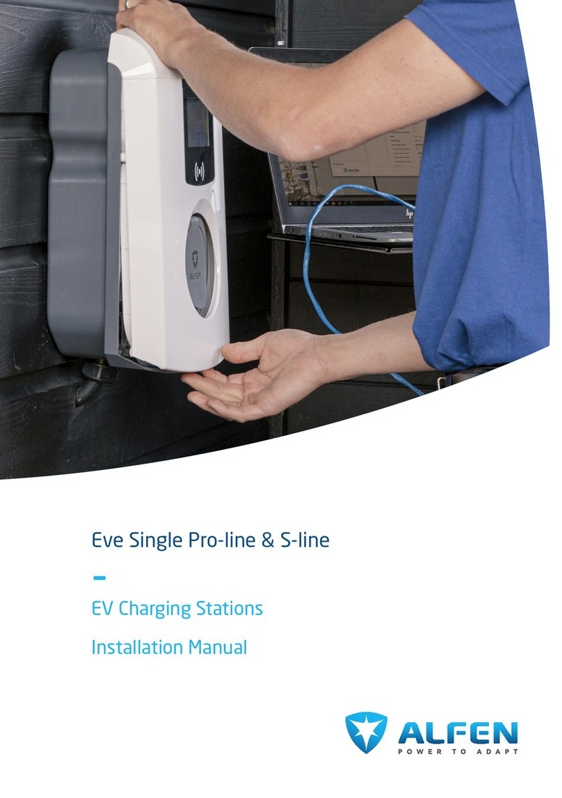
Eve Single Pro-line & S-line


Table Of Contents1. Safety and usage instructions 3
1.1 Explanation of text instructions used 3
1.1.1 Safety symbols 3
1.2 Purpose and intended audience 3
1.2.1 Improper use 3
1.3 Disclaimer 3
1.4 Software and complementary
documentation 4
1.5 Copyright 5
1.6 Operating conditions 5
1.7 EU Declaration of Conformity 5
1.8 About this document 6
2. Product overview 8
2.1 Scope of delivery Eve Single 8
2.2 Legend product overview exterior 9
2.3 Legend product overview interior 10
3. Installing and connecting 11
3.1 Safety announcements 11
3.2 Assembly and installation requirements 11
3.3 Preparation prior to installation 12
3.4 Installation tools 12
3.5 Installation procedure prerequisites 13
3.5.1 Data cable options 13
3.6 Mechanical installation procedure 13
3.6.1 Wall-mounting the charging station 14
3.7 Electrical installation procedure 24
3.7.1 Additional installation procedure for model
with fixed charging cable 26
3.8 Finishing the installation 28
4. Commissioning 31
4.1 Safety instructions before use 31
4.2 Initial start-up 31
4.3 Testing the socket(s) 31
5. Connectivity 32
5.1 Preparation prior to configuration using the
MyEve app 32
5.2 Preparation prior to configuration using the
ACE Service Installer 32
5.3 Configuring the charging station 32
5.3.1 Wireless connection 32
5.3.2 Wired network connection 32
5.3.3 Back office management systems 33
6. Disposal 34
6.1 Decommissioning and returning 34
6.2 Waste electrical and electronic equipment
(WEEE) 34
I
TABLE OF CONTENTS
EN
Alfen ICU B.V. | Installation Manual | Eve Single Pro-line & S-line | EV Charging Stations | V2.2 | EN | 04/2023 | 203130236-ICU
Safety and usage instructions1.1 Explanation of text instructions used
Safety warnings and precautions regarding Eve Single are
indicated in this document as follows:
DANGER
Signal word used to indicate an imminently hazardous
situation which, if not avoided, will result in death or serious
injury.
WARNING
Signal word used to indicate a potentially hazardous
situation which, if not avoided, could result in death or
serious injury
CAUTION
Signal word used to indicate a potentially hazardous
situation which, if not avoided, could result in minor or
moderate injury.
NOTE
Signal word used to provide additional information or
information on possible product damage.
1.1.1 Safety symbols
The following warning pictograms are attached to (parts
of) Eve Single:
Pictogram Description
Dangerous electrical volt-
age, attached to high-volt-
age electrical equipment
1.2 Purpose and intended audience
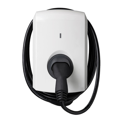
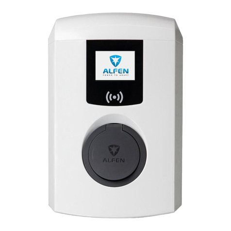
This manual applies to the Eve Single Pro-line andEve
SingleS-line (in this document also indicated as Eve Single,
Pro-line, S-line or “charging stations”) produced by Alfen ICU
B.V., Hefbrugweg 28, 1332AP Almere, the Netherlands, reg.
no. 64998363 (“Alfen”). The Alfen Eve Single is intended
exclusively for charging electric vehicles and, when installed
correctly, may be used by untrained individuals. Follow
this manual to install and commission the charging station
correctly.
Installation, commissioning and maintenance of this
charging station may only be performed by a qualified
electrician. It is essential that the qualified technician has:
•Expertise on all relevant general and specific rules
regarding safety and incident prevention
•Comprehensive knowledge of applicable electrical
regulations.
•The ability to identify risks and avoid potential hazards
•Received and read these installation and operation
instructions
1.2.1 Improper use
Using the charging station is safe when used as intended.
Any other use or changes to the charging station are
considered improper use and therefore not permitted.
The operator, owner or qualified technician is responsible
for any personal injury or material damage arising from
improper use.
1.3 Disclaimer
This document has been subjected to rigorous technical
review before being published. It is revised at regular
intervals, and any modifications and amendments are
included in the subsequent issues. Although Alfen has
made its best efforts to keep the document as precise and
up-to-date as possible, Alfen does not assume any liability
for defects and damage which results from the use of the
information contained herein.
NOTE
This manual is subject to updates and changes. The
latest version is available for download on https://
knowledge.alfen.com or Alfen.com. Errors and omissions
excepted.
Any deviation to the products as assembled by
Alfen including, but not limited to, customer-specific
modifications to the product such as the placement of
stickers, SIM cards or the usage of different colors (all
referred to as 'Customization') may affect the final product,
its experience, appearance, quality and / or lifespan (the
Customized Product). Alfen is not liable for any damage
to, or caused by, the Customized Product if this damage is
caused by this applied Customization.
EN
3
1. SAFETY AND USAGE INSTRUCTIONS
Alfen ICU B.V. | Installation Manual | Eve Single Pro-line & S-line | EV Charging Stations | V2.2 | EN | 04/2023 | 203130236-ICU

Alfen ICU B.V. shall not be liable in any way, for any kind of
damage, and the (carry in) warranty for the product and the
accessories shall not apply in the following cases:
•Failure to comply with the instructions in this manual in
general and with the operating conditions specifically.
•Improper use.
•External damage.
•Installation, commissioning or faulty repair or
maintenance by unqualified persons.
•Failures from the grid or the GPS / GPRS provider.
•Modification or configuration of the product or
accessories without the knowledge of Alfen ICU B.V..
•Use of spare parts not approved or manufactured by
Alfen.
•The charging station is used outside its operating
conditions as stated in this manual.
NOTE
In areas where the ambient temperature is below -25°C
or higher than 40-45°C the charging station will not
operate efficiently and may even shut off due to the
undercooling or overheating of components.
•Situations have occurred that are beyond the control of
Alfen ICU B.V. (force majeur).
•Malfunction of an open charge point back office.
•Damage to the electrical vehicle.
1.4 Software and complementary documentation
The charging station Eve Single uses the firmware version
6.xx at the time of writing.
NOTE
The most current firmware version is available for
download in the MyEve automatically. When using the ACE
Service Installer you need to manually update firmware
to the charging station via the menu “Device/Upload new
firmware...”
NOTE
It is possible to request a printed copy of this manual in
your language by Alfen at any time. Refer to the contact
data for your request.
Under the following links you can obtain detailed
information regarding the Eve Single S-line and Pro-line
charging stations.
Installation video
Eve SingleS-line
Installation video
Eve SinglePro-
line
YouTube channel Alfen - Power to
adapt
providing instal-
lation, service
and information
videos.
Data sheet Datasheet - Eve
Single S-line &
Pro-line
providing detailed
information on
models, techni-
cal features and
equipment.
Knowledge Base Knowledge Base providing FAQ
(frequently asked
questions) sec-
tion, service and
procedure instruc-
tions.
“Eichrecht Adden-
dum”
Available for
download on Ger-
man download
site under “An-
leitungen”
Document re-
quired for in-
stalling Pro-line
models with me-
ters according to
calibration regula-
tions in Germany.
Error code list Error codes and
troubleshooting
Error messages
displayed on Pro-
line models, (al-
so provided in the
Eve Single user
manual).
Declaration of
conformity
Please request at
your Alfen con-
tact.
1. SAFETY AND USAGE INSTRUCTIONS
Alfen ICU B.V. | Installation Manual | Eve Single Pro-line & S-line | EV Charging Stations | V2.2 | EN | 04/2023 | 203130236-ICU
4
EN

Smart Charging
configuration Eve
Single
Available for
download on the
Knowledge Base
Document re-
quired for con-
figuring Smart
Charging features.
Training for Alfen
charging stations
Trainings charging
stations equip-
ment
class-room train-
ings provided by
Alfen.
1.5 Copyright
Copyright ©2023 Alfen ICU B.V. All rights reserved. The
disclosure, duplication, distribution and editing of this
document, or utilization and communication of the content
are not permitted, unless authorized in writing by Alfen.
All rights, including rights created by a patent, grant or
registration of a utility model or a design, are reserved.
The English version of this manual is the original source
document. Manuals in other languages are translations of
this source document.
Eve Single is a trade mark by Alfen ICU B.V. Any
unauthorized use of the trade mark is therefore illegal.
1.6 Operating conditions
Operating temperature -25....+55°C
Relative atmospheric humidity 5 - 95%
Electrical safety class ClassI
Degree of protection (casing) IP55
IK protection (mechanical impact) IK10
NOTE
The operating temperature stated is under the following
conditions:
•A maximum charging power of 11kW is guaranteed at
an ambient temperature above 40°C and below the
stated maximum operating temperature.
•The influence of direct solar radiation on the charging
station is excluded.
•The influence of a front cover with another color than
RAL9016 is excluded.
•The influence of Customizations applied on the charging
station is excluded.
•The stated charging performance is solely applicable to
the charging station, actual performance is dependent
on the vehicle and the grid connection.
1.7 EU Declaration of Conformity
The Eve Single complies to the following directives:
•Low Voltage Directive 2014/35/EU
•EMC Directive 2014/30/EU
•Radio Equipment Directive 2014/53/EU
•Harmonized standards: IEC 61851-1 ed. 3 (2017) -
Electric vehicle conductive charging system - General
requirements, on national level implemented under:
AT: ÖVE/EN 61851-1
BE: NBN EN 61851-1
DE: DIN-EN 61851-1
FIN: SFS-EN 61851-1
FR: NF-EN 61851-1
NL: NEN-EN-IEC 61851-1
NO: NEK-EN-61851-1
UK: BS-EN 61851-1
ETSI EN 300 330-2 V1.5.1 – NFC reader
EN 301 908-1 V11.1.1 / EN 301 908-13
V11.1.2 / EN 301 511 V12.5.1 - GPRS
NOTE
The EU declaration of conformity can be requested from
Alfen. Please refer to the contact data on the backpage of
this manual.
EN
5
1. SAFETY AND USAGE INSTRUCTIONS
Alfen ICU B.V. | Installation Manual | Eve Single Pro-line & S-line | EV Charging Stations | V2.2 | EN | 04/2023 | 203130236-ICU

1.8 About this document
This section describes the used symbols, explains their meaning and shows how to use this document.
1
/
4
” T20
3x
12
34
5
1
/
4
” T20
No. Description Symbol Description Remark
Product overview
Scope of delivery
Mechanical installation procedure
Electrical installation procedure
Additional installation procedure for mod-
el with fixed charging cable
1 Symbol in the top left cor-
ner indicates the work step
within the installation pro-
cedure
Finishing the installation
2 Symbol with number indi-
cates the task to be done
within this work step
12
Number corresponds to the number with-
in the work step described in the corre-
sponding chapter
1. SAFETY AND USAGE INSTRUCTIONS
Alfen ICU B.V. | Installation Manual | Eve Single Pro-line & S-line | EV Charging Stations | V2.2 | EN | 04/2023 | 203130236-ICU
6
EN

No. Description Symbol Description Remark
dark blue to be provided by installer3 Symbols on the left hand
side indicate the parts re-
quired for this task
5x50 mm
light blue part of Alfen delivery
scope
4 The illustration visualizes
the task
Detailed description can be found in the
corresponding chapter
dark blue to be provided by installer5 Symbols in the top right
corner indicate the tools
required for this task
light blue part of Alfen delivery
scope
EN
7
1. SAFETY AND USAGE INSTRUCTIONS
Alfen ICU B.V. | Installation Manual | Eve Single Pro-line & S-line | EV Charging Stations | V2.2 | EN | 04/2023 | 203130236-ICU

Product overview2.1 Scope of delivery Eve Single
The information given in this table refers to illustration A.
A
1x
1x
**** ****
1x
5x50
mm
M8
8
mm
1
/
4
” T20
M8
M32x1,5
M32-M25
Symbol Description Quantity
Charging station:
•Eve Single S-line
•Eve Single Pro-line
1
Wall-mount frame 1
Torx T20 wrench 1
Spacing ring for cable
gland M32-M25
1
Symbol Description Quantity
RS-485 connector in-
cluding TIC protocol con-
nections
1
S-line Cable gland
M32x1.5
1
S-line Optional cable
gland M25x1.5
3
Pro-line Cable gland
M32x1.5
1
Pro-line Optional cable
gland M25x1.5
2
T20
M4x12
Torx bolt M4x8mm 6
2. PRODUCT OVERVIEW
Alfen ICU B.V. | Installation Manual | Eve Single Pro-line & S-line | EV Charging Stations | V2.2 | EN | 04/2023 | 203130236-ICU
8
EN

Symbol Description Quantity
8 mm
Wall plug 4.5-5x8mm 4
5x50 mm
Screw 5x50mm 4
M8
M8 nut 4
M8
M8 washer 4
Counter nut 1
Symbol Description Quantity
Reduction ring M32-25 1
Installation Manual 1
User Manual (to be hand-
ed over to the customer)
1
**** ****
Card with password (re-
covery) information (to
be handed over to the
customer)
1
2.2 Legend product overview exterior
The information given in this table refers to illustration B.
B
EN
9
2. PRODUCT OVERVIEW
Alfen ICU B.V. | Installation Manual | Eve Single Pro-line & S-line | EV Charging Stations | V2.2 | EN | 04/2023 | 203130236-ICU
Symbol Description
Wall-mount frame
Identification label
Symbol Description
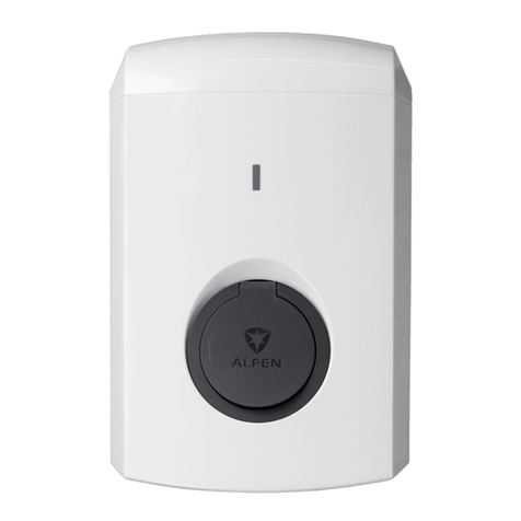
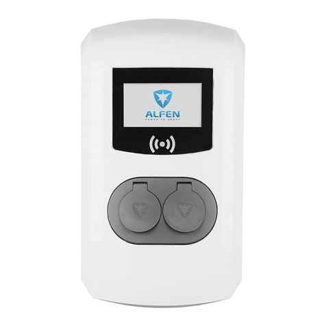
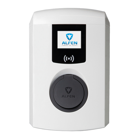
Pro-line model (with display) or S-line model
(with LED)
2.3 Legend product overview interior
The information given in this table refers to illustration C.
C
6
5
4
3
2a
2
2
2
11
11
11
87
No. Description
1 Bolts for front cover
2 Stud for assembly
2a Screws for wall-mount frame with earth con-
nection
3 RJ-45 connector
4 RJ-11 connector
No. Description
5 Terminal block for the power supply
6 Terminal block for the fixed charging cable
7 RS-485 connector
8 SIM cardholder
2. PRODUCT OVERVIEW
Alfen ICU B.V. | Installation Manual | Eve Single Pro-line & S-line | EV Charging Stations | V2.2 | EN | 04/2023 | 203130236-ICU
10
EN

Installing and connecting3.1 Safety announcements
DANGER
Risk of injury and electrocution. Installation,
(de)commissioning and maintenance of the charging
station may only be performed by a qualified electrician.
DANGER
Risk of injury and electrocution. Installing the charging
station incorrectly may result in fatal injury! When working
with electricity, failure to comply with relevant regulations
can lead to dangerous and life-threatening situations.
DANGER
Risk of electrocution. The electrical system must be
disconnected from every power source before performing
any installation or maintenance work!
DANGER
Risk of injury and electrocution. The charging station
contains electrical components that still contain a charge
after being disconnected from the system. Always wait 10
seconds after powering down before commencing to work.
WARNING
Risk of injuries, explosion or fire. Never install in a
potentially explosive atmosphere.
WARNING
Risk of electrocution. Never install in areas prone to
flooding without implementing compensatory measures.
WARNING
Risk of injury and electrocution. Installation work may not
be carried out during rain or if the air humidity exceeds
95%.
WARNING
Risk of injury and electrocution. The installation must be
performed by a qualified electrician who has read this
manual and will execute the installation in accordance
with the IEC 60364 (Electrical Installations for Buildings)
standard.
WARNING
Risk of damage or electrocution. A charging station must
always be installed on separate power circuit.
WARNING
Risk of damage or electrocution. Local conditions may
influence the installation requirements. Your installation
must comply with the standards and regulations of the
location (country) where it is installed.
CAUTION
Risk of injury and damage. The installer is always
responsible for choosing the correct cable diameter and
complying with the relevant standards and legislation.
CAUTION
Risk of injury and damage. The installation and cables
should be installed to match the maximum charging current
to the input of the charging station. This should assume
continual load.
CAUTION
Risk of injury and damage. Mechanical impact and/or
collisions might cause damage to the equipment. Protect
Alfen products installed in public areas and car park sites.
CAUTION
Risk of damage. Adapters or conversion adapters are not
allowed to be used.
3.2 Assembly and installation requirements
When selecting a location to install the charging station,
the following criteria must be taken into account:
•Always fully comply with local technical requirements
and safety regulations.
•The recommended installation height is 800 - 1200 mm
from the ground to the bottom of the casing.
•The charging port on the vehicle is easy to reach with
the (attached) charging cable.
•The charging station is installed at a location where the
charging cable (approx. 5 - 7.5m) can be used without
placing any tension on the cable.
Ensure that the following requirements for installing the
charging station have been met before starting:
•The cable trajectory from the main distributor to the
Eve Single must be secured against short-circuiting with
EN
11
3. INSTALLING AND CONNECTING
Alfen ICU B.V. | Installation Manual | Eve Single Pro-line & S-line | EV Charging Stations | V2.2 | EN | 04/2023 | 203130236-ICU
a B- or C-type circuit breaker (or other, in accordance
with local standards and regulations), or gG-type
fuses (or other, in accordance with local standards and
regulations).
•The cable trajectory must be equipped with 30-mA fault
current protection with a type A or B residual current
device (RCD).
•The earth leakage circuit breaker must be protected
against the maximum current the charging station can
process (20A or 40A)
•The cable trajectory and the charging station are part of
a TN-S system; the equipment must be earthed at the
main distributor or with an earth pin (TT). An energy grid
without a neutral conductor is not supported.
•The cable trajectory must be installed in accordance
with the usual local professional standards.
Please refer to the following table for safety options and
cable cross-sections advised.
Power supply cable: minimum advised cable cross-section
(based on assumed max. 50 m cable length)
•1-phase 3.7kW charging, 16A selected per phase:
3x4mm2
•3-phase 11kW charging, 16A selected per phase:
5x4mm2
•1-phase 7.4kW charging, 32A per phase: 3x6mm2
•3-phase 22kW charging, 32A per phase: 5x6mm2
Short-circuit protection:
With circuit breakers:
•1-phase 16A (3.7kW): 1 x 20A, 1P, type B or C
•3-phase 16A (11kW): 1 x 20A, 3P, type B or C
•1-phase 32A (7.4kW): 1 x 40A, 1P, type B or C
•3-phase 32A (22kW): 1 x 40A, 3P, type B or C
With fuses:
•1-phase 16A (3.7kW): 1 x 20A gG
•3-phase 16A (11kW): 3 x 20A gG
•1-phase 32A (7.4kW): 1. x 35A gG
•3-phase 32A (22kW): 3 x 35A gG
Earth leakage protection (possibly in combination with cir-
cuit breaker):
Residual current device: 30mA type A or B, 4P
•3.7kW/11kW charging: minimum 20A
•7.4kW/22kW charging: 40A
Nominal input voltage:
•VL1-N: 230V (+/-10%)
•VL2-N: 230V (+/-10%)
•VL3-N: 230V (+/-10%)
•VL1-L2: 400V (+/-10%)
•VL1-L3: 400V (+/-10%)
•VL2-L3: 400V (+/-10%)
•VPE-N: ≈ 0V
Nominal frequency: 50 Hz
Grounding:
•TN system: separate PE cable
•TT system: separately installed grounding electrode
<100Ohm spreading resistance
•IT system: connected to a shared reference (common
earth) with other metal parts
3.3 Preparation prior to installation
•View the site and determine the installation location.
•Check the scope of delivery and required parts.
•Read this installation manual before hand.
•Download the data sheet on Alfen.com for product-
specific information.
NOTE
There is a sticker inside the charging station indicating
the model name of the charging station.
•Download the Smart Charging Implementation Guide
on knowledge.alfen.com for detailed information on
configuring Smart Charging options.
3.4 Installation tools
Symbol Description
Pencil or marker
Wire stripper
Voltmeter or digital multimeter
PH4
Phillips screwdriver
3. INSTALLING AND CONNECTING
Alfen ICU B.V. | Installation Manual | Eve Single Pro-line & S-line | EV Charging Stations | V2.2 | EN | 04/2023 | 203130236-ICU
12
EN

Symbol Description
Small and large flathead screwdriv-
er
T20
T20 Torx driver
Ferrules (the diameter of the fer-
rule depends on the diameter of
the power wiring and the construc-
tion)
Spirit level
Machine drill
Torque driver (for terminal block
connections)
RJ-11
RJ-11 connector
RJ-45
RJ-45 connector
Crimping tool
3.5 Installation procedure prerequisites
•The installation position is a solid, right angled wall.
•In the surroundings of at least 5m of the installation
position there is no fire hazard.
•The power supply cable has been routed.
•The power cabinet has a RCD residual current device and
a MCD circuit breaker to connect the power cable.
•The electrical system has been disconnected from every
power source before performing any installation work.
3.5.1 Data cable options
•Connection to LAN via the RJ-45 connector
•Connection to smart meter via the RJ-11 connector
(Belgium and the Netherlands only)
•Connection to smart meter using the TIC protocol
(France only; provided within RS-485 connector)
•Connection to external energy meter via the RS-485
connector using the Modbus RTU protocol
•Connection to LAN and smart meter
•No connection to LAN or smart meter
3.6 Mechanical installation procedure
•Take the charging station out of the box.
•Use a non-scratching surface to put the charging station
down on to prevent damage.
•Check if all parts listed are provided.
NOTE
In the following text, only the wall-mounting installation
procedure is described. The Eve Single can also be mounted
on a pole. The pole is an accessory and the installation
instruction is provided within its scope of delivery.
EN
13
3. INSTALLING AND CONNECTING
Alfen ICU B.V. | Installation Manual | Eve Single Pro-line & S-line | EV Charging Stations | V2.2 | EN | 04/2023 | 203130236-ICU
3.6.1 Wall-mounting the charging station
1. Determine the position for the charging station at the preferred location:
a. Keep 300mm space clear on all sides around the charging station.
b. Choose a comfortable and ergonomically correct height (typically 800 - 1200mm).
c. Use a pencil and a spirit level to mark the top and bottom of the charging station.
1x
300 mm
300 mm
300 mm
300 mm
> 100 cm
3. INSTALLING AND CONNECTING
Alfen ICU B.V. | Installation Manual | Eve Single Pro-line & S-line | EV Charging Stations | V2.2 | EN | 04/2023 | 203130236-ICU
14
EN

2. Remove the wall-mount frame from the back of the charging station.
a. Remove the front cover and put aside.
NOTE
Do not lay down the charging station on a rough surface. Tip: Use the
packaging.
EN
15
3. INSTALLING AND CONNECTING
Alfen ICU B.V. | Installation Manual | Eve Single Pro-line & S-line | EV Charging Stations | V2.2 | EN | 04/2023 | 203130236-ICU
3. Unscrew the three Torx T20 screws (will be used again) of the transparent sub-frame and remove the sub-frame from
charging station.
T20
M4x12
1x
1
/
4
” T20
3. INSTALLING AND CONNECTING
Alfen ICU B.V. | Installation Manual | Eve Single Pro-line & S-line | EV Charging Stations | V2.2 | EN | 04/2023 | 203130236-ICU
16
EN

4. Use the wall-mount frame as a drilling template.
a. Use a spirit level to position the wall-mount frame.
b. Mark the drill holes, remove the wall-mount frame.
c. Drill the marked holes with a 8x50mm drill.
1x
8
mm
EN
17
3. INSTALLING AND CONNECTING
Alfen ICU B.V. | Installation Manual | Eve Single Pro-line & S-line | EV Charging Stations | V2.2 | EN | 04/2023 | 203130236-ICU
5. Install the wall-mount frame.
a. Use the 5x50mm wall plugs and screws provided.
1x
5x50 mm
4x
8 mm
4x
8
mm
5x50
mm
3. INSTALLING AND CONNECTING
Alfen ICU B.V. | Installation Manual | Eve Single Pro-line & S-line | EV Charging Stations | V2.2 | EN | 04/2023 | 203130236-ICU
18
EN
Other manuals for Eve Single Pro-Line
2
This manual suits for next models
1
Table of contents
Other alfen Batteries Charger manuals

alfen
alfen Twin 4XL Instruction Manual

alfen
alfen Eve Double Pro-line User manual

alfen
alfen Eve Double PG-line DE User manual

alfen
alfen Eve Double Pro-line FR User manual

alfen
alfen Eve Single S-Line User manual

alfen
alfen Eve Double PG-line DE User manual

alfen
alfen Eve Double Pro-line FR User manual

alfen
alfen Eve Single Pro-Line User manual

alfen
alfen Eve Double Pro-line User manual

alfen
alfen Eve User manual