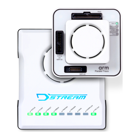
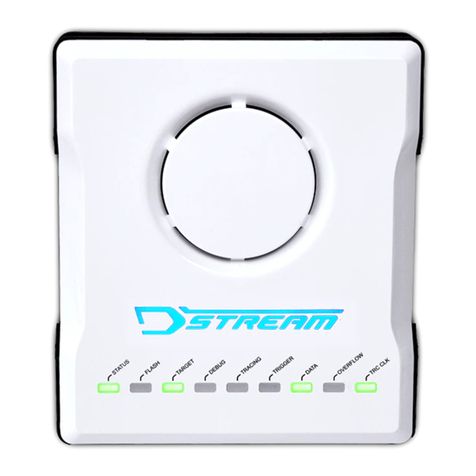
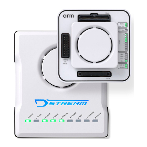
ARM DSTREAM-ST User manual

Arm® DSTREAM-ST
Version 1.0
System and Interface Design Reference Guide
Copyright © 2017–2019 Arm Limited or its affiliates. All rights reserved.
100893_0100_06_en

Arm® DSTREAM-ST
System and Interface Design Reference Guide
Copyright © 2017–2019 Arm Limited or its affiliates. All rights reserved.
Release Information
Document History
Issue Date Confidentiality Change
0100-00 31 March 2017 Non-Confidential First release
0100-01 24 November 2017 Non-Confidential Documentation update for version 1.0 release
0100-02 22 June 2018 Non-Confidential Documentation update for version 1.0 release
0100-03 05 April 2019 Non-Confidential Documentation update for version 1.0 release
0100-04 18 April 2019 Non-Confidential Document update to add the Conformance Notices
0100-05 30 April 2019 Non-Confidential Documentation update for version 1.0 release
0100-06 13 December 2019 Non-Confidential Documentation update for version 1.0 release
Non-Confidential Proprietary Notice
This document is protected by copyright and other related rights and the practice or implementation of the information contained in
this document may be protected by one or more patents or pending patent applications. No part of this document may be
reproduced in any form by any means without the express prior written permission of Arm. No license, express or implied, by
estoppel or otherwise to any intellectual property rights is granted by this document unless specifically stated.
Your access to the information in this document is conditional upon your acceptance that you will not use or permit others to use
the information for the purposes of determining whether implementations infringe any third party patents.
THIS DOCUMENT IS PROVIDED “AS IS”. ARM PROVIDES NO REPRESENTATIONS AND NO WARRANTIES,
EXPRESS, IMPLIED OR STATUTORY, INCLUDING, WITHOUT LIMITATION, THE IMPLIED WARRANTIES OF
MERCHANTABILITY, SATISFACTORY QUALITY, NON-INFRINGEMENT OR FITNESS FOR A PARTICULAR PURPOSE
WITH RESPECT TO THE DOCUMENT. For the avoidance of doubt, Arm makes no representation with respect to, and has
undertaken no analysis to identify or understand the scope and content of, third party patents, copyrights, trade secrets, or other
rights.
This document may include technical inaccuracies or typographical errors.
TO THE EXTENT NOT PROHIBITED BY LAW, IN NO EVENT WILL ARM BE LIABLE FOR ANY DAMAGES,
INCLUDING WITHOUT LIMITATION ANY DIRECT, INDIRECT, SPECIAL, INCIDENTAL, PUNITIVE, OR
CONSEQUENTIAL DAMAGES, HOWEVER CAUSED AND REGARDLESS OF THE THEORY OF LIABILITY, ARISING
OUT OF ANY USE OF THIS DOCUMENT, EVEN IF ARM HAS BEEN ADVISED OF THE POSSIBILITY OF SUCH
DAMAGES.
This document consists solely of commercial items. You shall be responsible for ensuring that any use, duplication or disclosure of
this document complies fully with any relevant export laws and regulations to assure that this document or any portion thereof is
not exported, directly or indirectly, in violation of such export laws. Use of the word “partner” in reference to Arm’s customers is
not intended to create or refer to any partnership relationship with any other company. Arm may make changes to this document at
any time and without notice.
If any of the provisions contained in these terms conflict with any of the provisions of any click through or signed written
agreement covering this document with Arm, then the click through or signed written agreement prevails over and supersedes the
conflicting provisions of these terms. This document may be translated into other languages for convenience, and you agree that if
there is any conflict between the English version of this document and any translation, the terms of the English version of the
Agreement shall prevail.
The Arm corporate logo and words marked with ® or ™ are registered trademarks or trademarks of Arm Limited (or its
subsidiaries) in the US and/or elsewhere. All rights reserved. Other brands and names mentioned in this document may be the
trademarks of their respective owners. Please follow Arm’s trademark usage guidelines at http://www.arm.com/company/policies/
trademarks.
Arm® DSTREAM-ST
100893_0100_06_en Copyright © 2017–2019 Arm Limited or its affiliates. All rights
reserved.
2
Non-Confidential
Copyright © 2017–2019 Arm Limited (or its affiliates). All rights reserved.
Arm Limited. Company 02557590 registered in England.
110 Fulbourn Road, Cambridge, England CB1 9NJ.
LES-PRE-20349
Confidentiality Status
This document is Non-Confidential. The right to use, copy and disclose this document may be subject to license restrictions in
accordance with the terms of the agreement entered into by Arm and the party that Arm delivered this document to.
Unrestricted Access is an Arm internal classification.
Product Status
The information in this document is Final, that is for a developed product.
Web Address
www.arm.com
Conformance Notices
This section contains conformance notices.
Federal Communications Commission Notice
This device is test equipment and consequently is exempt from part 15 of the FCC Rules under section 15.103 (c).
Class A
Important: This is a Class A device. In residential areas, this device may cause radio interference. The user should take the
necessary precautions, if appropriate.
CE Conformity
The Waste Electrical and Electronic Equipment (WEEE) marking, that is, the crossed out wheelie-bin figure, indicates that this
product must not be disposed of with general waste within the European Union. To prevent possible harm to the environment from
uncontrolled waste disposal, the user is required to recycle the product responsibly to promote reuse of material resources. To
comply with EU law, you must dispose of the product in one of the following ways:
• Return it to the distributer where it was purchased. The distributer is required to arrange free collection when requested.
• Recycle it using local WEEE recycling facilities. These facilities are now very common and might provide free collection.
• If purchased directly from Arm, Arm provides free collection. Please e-mail [email protected] for instructions.
The CE Declaration of Conformity for this product is available on request.
The system should be powered down when not in use.
It is recommended that ESD precautions be taken when handling this product.
The product generates, uses, and can radiate radio frequency energy and may cause harmful interference to radio communications.
There is no guarantee that interference will not occur in a particular installation. If this equipment causes harmful interference to
radio or television reception, which can be determined by turning the equipment off or on, you are encouraged to try to correct the
interference by one or more of the following measures:
• Ensure attached cables do not lie across any sensitive equipment.
• Reorient the receiving antenna.
• Increase the distance between the equipment and the receiver.
• Connect the equipment into an outlet on a circuit different from that to which the receiver is connected.
• Consult the dealer or an experienced radio/TV technician for help.
Note
It is recommended that wherever possible shielded interface cables be used.
Arm® DSTREAM-ST
100893_0100_06_en Copyright © 2017–2019 Arm Limited or its affiliates. All rights
reserved.
3
Non-Confidential

Contents
Arm® DSTREAM-ST System and Interface Design
Reference Guide
Preface
About this book ..................................................... ..................................................... 10
Chapter 1 Debug and trace interface
1.1 JTAG signals ..................................................... ..................................................... 1-13
1.2 Return Clock (RTCK) signal .................................................................................... 1-18
1.3 Reset signals ..................................................... ..................................................... 1-19
1.4 Run-Control signals ................................................ ................................................ 1-21
1.5 Serial Wire Debug (SWD) signals ..................................... ..................................... 1-22
1.6 Trace signals ..................................................... ..................................................... 1-24
1.7 Target Voltage Reference (VTREF) signals ............................................................ 1-26
1.8 I/O diagrams for DSTREAM-ST signals .................................................................. 1-28
1.9 Typical SWD circuit .................................................................................................. 1-30
1.10 Typical JTAG circuit ................................................ ................................................ 1-31
Chapter 2 Target interface connectors
2.1 Target connector selection guide ...................................... ...................................... 2-33
2.2 Arm JTAG 20 connector .......................................................................................... 2-34
2.3 CoreSight™ 10 connector ............................................ ............................................ 2-35
2.4 CoreSight™ 20 connector ............................................ ............................................ 2-36
2.5 TI JTAG 14 connector .............................................................................................. 2-38
2.6 Mictor 38 connector ................................................ ................................................ 2-39
100893_0100_06_en Copyright © 2017–2019 Arm Limited or its affiliates. All rights
reserved.
4
Non-Confidential

2.7 MIPI 34 connector ................................................. ................................................. 2-41
2.8 MIPI 60 connector ................................................. ................................................. 2-43
2.9 Auxiliary (AUX) connector ........................................... ........................................... 2-45
2.10 User I/O connector .................................................................................................. 2-46
Chapter 3 Target board design
3.1 Overview of high-speed design ....................................... ....................................... 3-48
3.2 JTAG port buffering ................................................ ................................................ 3-51
3.3 Series termination .................................................................................................... 3-54
3.4 Modeling .................................................................................................................. 3-55
3.5 Target design checklist ............................................................................................ 3-56
100893_0100_06_en Copyright © 2017–2019 Arm Limited or its affiliates. All rights
reserved.
5
Non-Confidential

List of Figures
Arm® DSTREAM-ST System and Interface Design
Reference Guide
Figure 1-1 Simple JTAG connection ....................................................................................................... 1-13
Figure 1-2 Chained JTAG connection ..................................................................................................... 1-14
Figure 1-3 JTAG timing diagram ............................................................................................................. 1-15
Figure 1-4 Basic JTAG port synchronizer ............................................................................................... 1-16
Figure 1-5 Timing diagram for the Basic JTAG synchronizer .................................................................. 1-16
Figure 1-6 JTAG port synchronizer for single rising-edge D-type ASIC design rules ............................. 1-16
Figure 1-7 Timing diagram for the D-type JTAG synchronizer ................................................................ 1-17
Figure 1-8 Example reset circuit ............................................................................................................. 1-20
Figure 1-9 SWD timing diagrams ............................................................................................................ 1-22
Figure 1-10 TRACECLK timing diagram ................................................................................................... 1-25
Figure 1-11 Target interface logic levels ................................................................................................... 1-26
Figure 1-12 Input/Output signals ............................................................................................................... 1-28
Figure 1-13 TCK signal ............................................................................................................................. 1-28
Figure 1-14 Reset signals ......................................................................................................................... 1-28
Figure 1-15 Trace signals .......................................................................................................................... 1-29
Figure 1-16 VTREF signals ....................................................................................................................... 1-29
Figure 1-17 Typical SWD circuit ................................................................................................................ 1-30
Figure 1-18 Typical JTAG circuit ............................................................................................................... 1-31
Figure 2-1 Arm JTAG 20 connector pinout .............................................................................................. 2-34
Figure 2-2 CoreSight 10 connector pinout .............................................................................................. 2-35
Figure 2-3 CoreSight 20 connector pinout .............................................................................................. 2-36
Figure 2-4 TI JTAG 14 connector pinout ................................................................................................. 2-38
100893_0100_06_en Copyright © 2017–2019 Arm Limited or its affiliates. All rights
reserved.
6
Non-Confidential

Figure 2-5 Mictor 38 connector pinout .................................................................................................... 2-39
Figure 2-6 MIPI 34 connector pinout ....................................................................................................... 2-41
Figure 2-7 MIPI 60 connector pinout ....................................................................................................... 2-43
Figure 2-8 User I/O connector pinout ...................................................................................................... 2-46
Figure 3-1 Point-to-point signal ............................................................................................................... 3-48
Figure 3-2 Stub length ............................................................................................................................ 3-48
Figure 3-3 Long stub causing false edges .............................................................................................. 3-49
Figure 3-4 Improved route with shorter stub ........................................................................................... 3-49
Figure 3-5 JTAG connection without buffers ........................................................................................... 3-51
Figure 3-6 JTAG connection with TDO buffer ......................................................................................... 3-51
Figure 3-7 Daisy-chained JTAG connection without buffers ................................................................... 3-51
Figure 3-8 Daisy-chained JTAG connection with TCK buffers ................................................................ 3-52
Figure 3-9 Fully buffered JTAG connection ............................................................................................. 3-52
100893_0100_06_en Copyright © 2017–2019 Arm Limited or its affiliates. All rights
reserved.
7
Non-Confidential

List of Tables
Arm® DSTREAM-ST System and Interface Design
Reference Guide
Table 1-1 JTAG timing Characteristics .................................................................................................. 1-15
Table 1-2 SWD timing requirements ...................................................................................................... 1-23
Table 1-3 TRACECLK characteristics ................................................................................................... 1-25
Table 2-1 Connector attributes .............................................................................................................. 2-33
Table 2-2 Arm JTAG 20 pinout table ...................................................................................................... 2-34
Table 2-3 Arm CoreSight 10 pinout table .............................................................................................. 2-35
Table 2-4 Arm CoreSight 20 pinout table (DSTREAMCS20=0) ............................................................ 2-36
Table 2-5 Arm CoreSight 20 pinout table (DSTREAMCS20=1) ............................................................ 2-37
Table 2-6 TI JTAG 14 pinout table ......................................................................................................... 2-38
Table 2-7 Mictor 38 pinout table ............................................................................................................ 2-39
Table 2-8 MIPI 34 pinout table ............................................................................................................... 2-41
Table 2-9 MIPI 60 pinout table ............................................................................................................... 2-43
Table 2-10 User I/O pinout table .............................................................................................................. 2-46
Table 3-1 Typical series terminating resistor values .............................................................................. 3-54
Table 3-2 Target design checklist .......................................................................................................... 3-56
100893_0100_06_en Copyright © 2017–2019 Arm Limited or its affiliates. All rights
reserved.
8
Non-Confidential

About this book
DSTREAM-ST System and Interface Design Reference Guide describes the interfaces of the
DSTREAM-ST debug and trace unit, with details about designing Arm architecture-based devices and
PCBs. This document is written for those using DSTREAM-ST or those designing PCBs.
Using this book
This book is organized into the following chapters:
Chapter 1 Debug and trace interface
The Arm debug and trace interface enables powerful software debug and optimization on an Arm
processor-based target system. It is based on the IEEE 1149.1 (JTAG) interface coupled with
various additional signals. This chapter introduces these signals and describes their use within the
interface.
Chapter 2 Target interface connectors
DSTREAM-ST has an Arm JTAG 20 connector, a CoreSight 20 connector, an auxiliary
connector, and a user I/O connector.
Chapter 3 Target board design
When you design a target board to connect to the DSTREAM-ST unit, you must consider the
rules that are discussed in this chapter.
Glossary
The Arm® Glossary is a list of terms used in Arm documentation, together with definitions for those
terms. The Arm Glossary does not contain terms that are industry standard unless the Arm meaning
differs from the generally accepted meaning.
See the Arm® Glossary for more information.
Typographic conventions
italic
Introduces special terminology, denotes cross-references, and citations.
bold
Highlights interface elements, such as menu names. Denotes signal names. Also used for terms
in descriptive lists, where appropriate.
monospace
Denotes text that you can enter at the keyboard, such as commands, file and program names,
and source code.
monospace
Denotes a permitted abbreviation for a command or option. You can enter the underlined text
instead of the full command or option name.
monospace italic
Denotes arguments to monospace text where the argument is to be replaced by a specific value.
monospace bold
Denotes language keywords when used outside example code.
<and>
Encloses replaceable terms for assembler syntax where they appear in code or code fragments.
For example:
MRC p15, 0, <Rd>, <CRn>, <CRm>, <Opcode_2>
Preface
About this book
100893_0100_06_en Copyright © 2017–2019 Arm Limited or its affiliates. All rights
reserved.
10
Non-Confidential

SMALL CAPITALS
Used in body text for a few terms that have specific technical meanings, that are defined in the
Arm® Glossary. For example, IMPLEMENTATION DEFINED, IMPLEMENTATION SPECIFIC, UNKNOWN, and
UNPREDICTABLE.
Feedback
Feedback on this product
If you have any comments or suggestions about this product, contact your supplier and give:
• The product name.
• The product revision or version.
• An explanation with as much information as you can provide. Include symptoms and diagnostic
procedures if appropriate.
Feedback on content
If you have comments on content then send an e-mail to [email protected]. Give:
• The title Arm DSTREAM-ST System and Interface Design Reference Guide.
• The number 100893_0100_06_en.
• If applicable, the page number(s) to which your comments refer.
• A concise explanation of your comments.
Arm also welcomes general suggestions for additions and improvements.
Note
Arm tests the PDF only in Adobe Acrobat and Acrobat Reader, and cannot guarantee the quality of the
represented document when used with any other PDF reader.
Other information
•Arm® Developer.
•Arm® Information Center.
•Arm® Technical Support Knowledge Articles.
•Technical Support.
•Arm® Glossary.
Preface
About this book
100893_0100_06_en Copyright © 2017–2019 Arm Limited or its affiliates. All rights
reserved.
11
Non-Confidential

Chapter 1
Debug and trace interface
The Arm debug and trace interface enables powerful software debug and optimization on an Arm
processor-based target system. It is based on the IEEE 1149.1 (JTAG) interface coupled with various
additional signals. This chapter introduces these signals and describes their use within the interface.
Note
• Unless otherwise specified, all pull-up/pull-down resistors that are discussed in this chapter must be
between 1K and 100K (10K is recommended).
• Unless otherwise specified, any signals beginning with a lowercase ‘n’ are, by default, active-LOW.
It contains the following sections:
•1.1 JTAG signals on page 1-13.
•1.2 Return Clock (RTCK) signal on page 1-18.
•1.3 Reset signals on page 1-19.
•1.4 Run-Control signals on page 1-21.
•1.5 Serial Wire Debug (SWD) signals on page 1-22.
•1.6 Trace signals on page 1-24.
•1.7 Target Voltage Reference (VTREF) signals on page 1-26.
•1.8 I/O diagrams for DSTREAM-ST signals on page 1-28.
•1.9 Typical SWD circuit on page 1-30.
•1.10 Typical JTAG circuit on page 1-31.
100893_0100_06_en Copyright © 2017–2019 Arm Limited or its affiliates. All rights
reserved.
1-12
Non-Confidential

1.1 JTAG signals
Most Arm-based devices are physically equipped with several pins that are dedicated to debug and test
purposes. Four of these pins make up the IEEE 1149.1 interface, also known as the JTAG interface. This
interface is often used for boundary-scan testing during the manufacture of printed circuit boards. The
interface also provides a useful way to access one or more cores and other components in a device, while
running its application software.
Test Data In (TDI)
The TDI signal is an input to the target device which provides a stream of serial data from the debug
unit.
The TDI signal must be pulled HIGH on the target to keep the signal inactive when no debug unit is
connected.
Test Mode Select (TMS)
The TMS signal is an input to the target device which controls its JTAG state-machine.
The TMS signal must be pulled HIGH on the target to keep the signal inactive when no debug unit is
connected.
Test Clock (TCK)
The TCK signal is an input to the target device which synchronizes its JTAG state-machine. On each
rising edge of the TCK signal, the target samples the TDI, and TMS signals.
Consider TCK as a strobe signal, rather than a clock signal, because it is typically non-continuous and
only becomes active during debug communications.
TCK can be pulled HIGH on the target, however, to maintain full compatibility with other JTAG
equipment, Arm recommends you pull TCK LOW.
Test Data Out (TDO)
The TDO signal is an output from the target device which returns a stream of serial data to the debug
unit.
TDO can be left floating on the target, however, to maintain full compatibility with other JTAG
equipment, Arm recommends you pull TDO HIGH.
Basic JTAG connection
In the simplest form (omitting pull-up and pull-down resistors), a connection between the debug unit and
the target device looks like:
Target
Device
Debug
Unit
TDI
TMS
TCK
TDO
TDI
TMS
TCK
TDO
Figure 1-1 Simple JTAG connection
Note
The naming convention of the TDI (Test Data In) and TDO (Test Data Out) signals is always with
respect to the target device.
1 Debug and trace interface
1.1 JTAG signals
100893_0100_06_en Copyright © 2017–2019 Arm Limited or its affiliates. All rights
reserved.
1-13
Non-Confidential

The flexible design of the JTAG interface enables you to connect multiple devices to a single debug unit:
Target
Device
Debug
Unit
TDI
TMS
TCK
TDO
TDI
TMS
TCK
TDO
Target
Device
TDI
TMS
TCK
TDO
Figure 1-2 Chained JTAG connection
A group of JTAG devices that are linked or daisy-chained together is often known as the JTAG chain or
scan-chain.
Warning
When multiple devices are used in a scan-chain, the TCK and TMS signals must be branched to each
device. Good digital design practice must be used to ensure that these branches do not reduce the signal
integrity of the signals causing false edges to be received by the devices.
For more information, see JTAG port buffering on page 3-51.
JTAG timing characteristics
The JTAG timing characteristics of DSTREAM-ST conform to the requirements of the IEEE 1149.1
(JTAG) specification.
TDI and TMS are set up by DSTREAM-ST on the falling edge of TCK. These signals are then sampled
by the target device on the rising edge of TCK. The target device must set up its TDO signal when it
detects the falling edge of TCK which, in turn, will be sampled by DSTREAM-ST on the next rising
edge of TCK.
These timings are considered correct at the debug connector of the target board.
Basic JTAG timing:
1 Debug and trace interface
1.1 JTAG signals
100893_0100_06_en Copyright © 2017–2019 Arm Limited or its affiliates. All rights
reserved.
1-14
Non-Confidential

TCK
TDI
TMS
TDO
Debug unit
sets up TDI
and TMS
Target device
samples TDI
and TMS
Target
device sets
up TDO
Tclk
Figure 1-3 JTAG timing diagram
Since all signals are set up on the falling edge of TCK and sampled on the rising edge, the effective
setup and hold times for the target device and DSTREAM-ST are approximately Tclk/2.
Issues with signal timing can usually be resolved by decreasing the TCK frequency. Decreasing the
TCK frequency increases the setup and hold times.
TDO is always slightly delayed, relative to the other signals, because it takes a finite amount of time for
the target device to detect the falling edge of TCK and then set up TDO. This slight delay, and the
round-trip delay of the debug cable, are compensated for by the DSTREAM-ST unit.
Note
There are no separate timing requirements for the adaptive clocking mode. In adaptive clocking mode,
the DSTREAM-ST samples TDO on the rising edge of RTCK instead of TCK, so TDO timing is
relative to RTCK.
Table 1-1 JTAG timing Characteristics
Parameter Min Max Description
F[clk] 10Hz 180MHz TCK frequency
T[clk] 5.556ns 100ms TCK period
T[ds] 49% 51% TCK Duty Cycle
For further details on the JTAG interface, a full specification is available from: www.ieee.com.
Synchronization
As debug data is transferred to and from the target device, it must pass between two clock domains
(TCK and the internal system clock of the target device). To achieve synchronized data transfer without
suffering any meta-stability issues, a synchronizer circuit must be used within the target device.
The following figure shows a circuit for a basic JTAG port synchronizer.
1 Debug and trace interface
1.1 JTAG signals
100893_0100_06_en Copyright © 2017–2019 Arm Limited or its affiliates. All rights
reserved.
1-15
Non-Confidential

nTRST
CLK
TCK
TDO
TMO
TDI
ASIC
nCLR
DQDQ
nCLR
RTCK
TDO
TCK
nTRST
CLK
TMS
TDI
Figure 1-4 Basic JTAG port synchronizer
The following figure shows a partial timing diagram for the basic JTAG synchronizer. To reduce the
delay, and because the second flip-flop only provides better immunity to metastability problems, clock
the flip-flops from opposite edges of the system clock.
CLK
TCK
RTCK
Figure 1-5 Timing diagram for the Basic JTAG synchronizer
ASIC design rules often impose a restriction that all flip-flops in a design must be clocked by one edge
of a single clock. To interface the clocking restriction to a JTAG port that is asynchronous to the system,
you must convert the JTAG TCK events into clock enables for this single clock. You must also ensure
that the JTAG port cannot overrun this synchronization delay.
One possible implementation of this circuit, is:
CKEN
IN
nRESET
TMS
CKEN TAP Ctrl
State
Machine
OUT
Scan
Chain
CKEN
TCKFallingEn
TCKRisingEn
Shift En
DQ
nCLR
D Q
nCLR
D Q
nCLR
D Q
TDO
TMS
CLK
nTRST
TCK
RTCK
TDI
Figure 1-6 JTAG port synchronizer for single rising-edge D-type ASIC design rules
1 Debug and trace interface
1.1 JTAG signals
100893_0100_06_en Copyright © 2017–2019 Arm Limited or its affiliates. All rights
reserved.
1-16
Non-Confidential

The following figure shows a corresponding partial timing diagram, and how TCKFallingEn and
TCKRisingEn are each active for exactly one period of CLK. It also shows how these enable signals
gate the RTCK and TDO signals so that they only change state at the edges of TCK.
CLK
TCKRisingEn
TCK
TCKFallingEn
RTCK
TAPC
State
TDO
Figure 1-7 Timing diagram for the D-type JTAG synchronizer
1 Debug and trace interface
1.1 JTAG signals
100893_0100_06_en Copyright © 2017–2019 Arm Limited or its affiliates. All rights
reserved.
1-17
Non-Confidential
1.2 Return Clock (RTCK) signal
Occasionally, a target device requires the JTAG interface to be externally synchronized to a clock within
the device due to it being slow, non-continuous, or variable. The adaptive clocking feature uses the
Return Clock signal (RTCK) to address this requirement.
The RTCK signal is an output from the target device which is typically fed from the last flip-flop in the
synchronization chain.
If used, the RTCK signal must be pulled LOW on the target.
Warning
RTCK should never be directly linked to TCK on the target board. If it is directly linked, it is likely to
cause false clock-edges to be received by the TCK input of the target device.
Adaptive clocking
When adaptive clocking is enabled, the debug unit issues a TCK signal and waits for the RTCK signal
to return before sampling TDO. The debug unit does not progress to the next TCK transition until
RTCK is received, allowing the target device to control the flow of the JTAG interface, as required.
Note
• If you use the adaptive clocking feature, then the transmission delays, gate delays, and
synchronization requirements might result in a lower clock frequency, compared to using fixed
clocking. Adaptive clocking mode is not recommended unless the target design requires it.
• Adaptive clocking can be enabled using the configuration settings in Arm Development Studio. For
more information, see Debug Hardware configuration in the Arm Development Studio User Guide.
• If adaptive clocking is used, the debug unit cannot detect the clock speed, and therefore cannot scale
its internal timeouts. If the target clock frequency is too low, a JTAG timeout might occur, leaving the
JTAG interface in an unknown state. To recover the connection, you must reset the debug unit. To
disable JTAG timeouts, use the configuration settings in Arm Development Studio. For more
information, see Debug Hardware configuration in the Arm Development Studio User Guide.
1 Debug and trace interface
1.2 Return Clock (RTCK) signal
100893_0100_06_en Copyright © 2017–2019 Arm Limited or its affiliates. All rights
reserved.
1-18
Non-Confidential
1.3 Reset signals
Arm debug units have the ability to control two reset signals on the target: nSRST and nTRST.
System Reset (nSRST)
The system reset signal, sometimes known as nRESET or HRESET, is an input to the target which
performs a warm boot of the core (or cores) and other devices in the target system. It is often asserted by
one or more of these conditions:
• Power On Reset (POR)
• Manual push-button reset
• Remote reset from a debug unit
• Watchdog reset
When no debug unit is connected, unintended resets can occur. To avoid unintended resets, the nSRST
signal must be pulled to its inactive logic level on the target.
By default, the nSRST signal has a logic level of active LOW. To avoid unintended resets, pull the nSRST
signal HIGH.
The polarity of the nSRST signal is configurable in Arm Development Studio.
TAP Reset (nTRST)
The TAP reset signal initializes the Test Access Port, debug logic, and boundary scan cells in the target
device.
When no debug unit is connected, unintended resets can occur. To avoid unintended resets, the nTRST
signal must be pulled to its inactive logic level on the target.
By default, the nTRST signal has a logic level of active LOW. To avoid unintended resets, pull the nTRST
signal HIGH.
The polarity of the nTRST signal is configurable in Arm Development Studio.
Note
Arm strongly recommends that the nSRST and nTRST signals are separately available on the JTAG
connector. If the nSRST and nTRST signals are linked together, resetting the system also resets the TAP
controller, which means:
• Depending on your target, it might not be possible to debug a system from reset because any
breakpoints previously set might be lost.
• You might need to restart the debug session because the JTAG interface might not recover when the
TAP controller state is changed.
It is expected that the assertion of the nSRST line by the DSTREAM-ST unit causes a warm reset of the
target system. If the nSRST line triggers a full, Power On Reset (POR), then the debug connection might
be lost.
With regards to the reset signals output from the DSTREAM-ST unit, the strong pull-up/pull-down
resistance is approximately 33Ω, and the weak pull-up/pull-down resistance is approximately 4.7kΩ.
Because it is possible to switch the polarity and drive strength of nTRST and nSRST, target systems
with various different reset configurations are supported.
Example reset circuit
A typical reset circuit which would be present on the target board, is:
1 Debug and trace interface
1.3 Reset signals
100893_0100_06_en Copyright © 2017–2019 Arm Limited or its affiliates. All rights
reserved.
1-19
Non-Confidential

Target
Device
nTRST
nRESET
nRST
Manual
Reset
10K
100R
SYSTEM RESET
Open-drain
reset device
e.g. STM1001
10K
100nF
TAP RESET
Other
Devices
Debug
Connector
nTRST
nSRST
VDD
VDD VDD
Figure 1-8 Example reset circuit
The push-button, 100R resistor, and 100nF capacitor shown here are an example of how a manual reset
button can be interfaced with the nSRST signal. This is optional and would typically be used on
development boards.
The reset device that is shown here would keep the target device, and any other system devices, in their
reset state until the power rail has reached a minimum valid voltage. If the target device has a separate
Power On Reset (POR) input, any voltage monitoring devices would typically connect to that instead. If
the target device is equipped with internal voltage monitoring circuitry, external monitoring devices can
be omitted.
1 Debug and trace interface
1.3 Reset signals
100893_0100_06_en Copyright © 2017–2019 Arm Limited or its affiliates. All rights
reserved.
1-20
Non-Confidential
Other manuals for DSTREAM-ST
3
Table of contents
Other ARM Computer Hardware manuals

ARM
ARM DSTREAM User instructions

ARM
ARM ARM7TDMI Product manual

ARM
ARM OKI ML671000 User manual

ARM
ARM Versatile/IT1 User manual

ARM
ARM Cortex-A76 Core Product manual

ARM
ARM MPS2 Product manual

ARM
ARM Cortex-M3 DesignStart Product manual

ARM
ARM MPS3 User manual

ARM
ARM DSTREAM-XT User manual

ARM
ARM ARM9TDMI Product manual

ARM
ARM ARM946E-S Product manual

ARM
ARM DSTREAM User instructions

ARM
ARM ARM710T User manual

ARM
ARM Cortex-M3 DesignStart Product manual

ARM
ARM DSTREAM DS-5 User manual

ARM
ARM Cortex A9 Product manual

ARM
ARM ARM926EJ-S Product manual

ARM
ARM Cortex-A35 Product manual

ARM
ARM Cortex-M0 Product manual

ARM
ARM ARM1176JZF-S Product manual