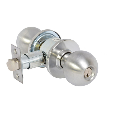
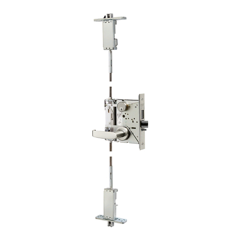
Assa Abloy 8800 Series User manual
Other Assa Abloy Door Lock manuals
Assa Abloy
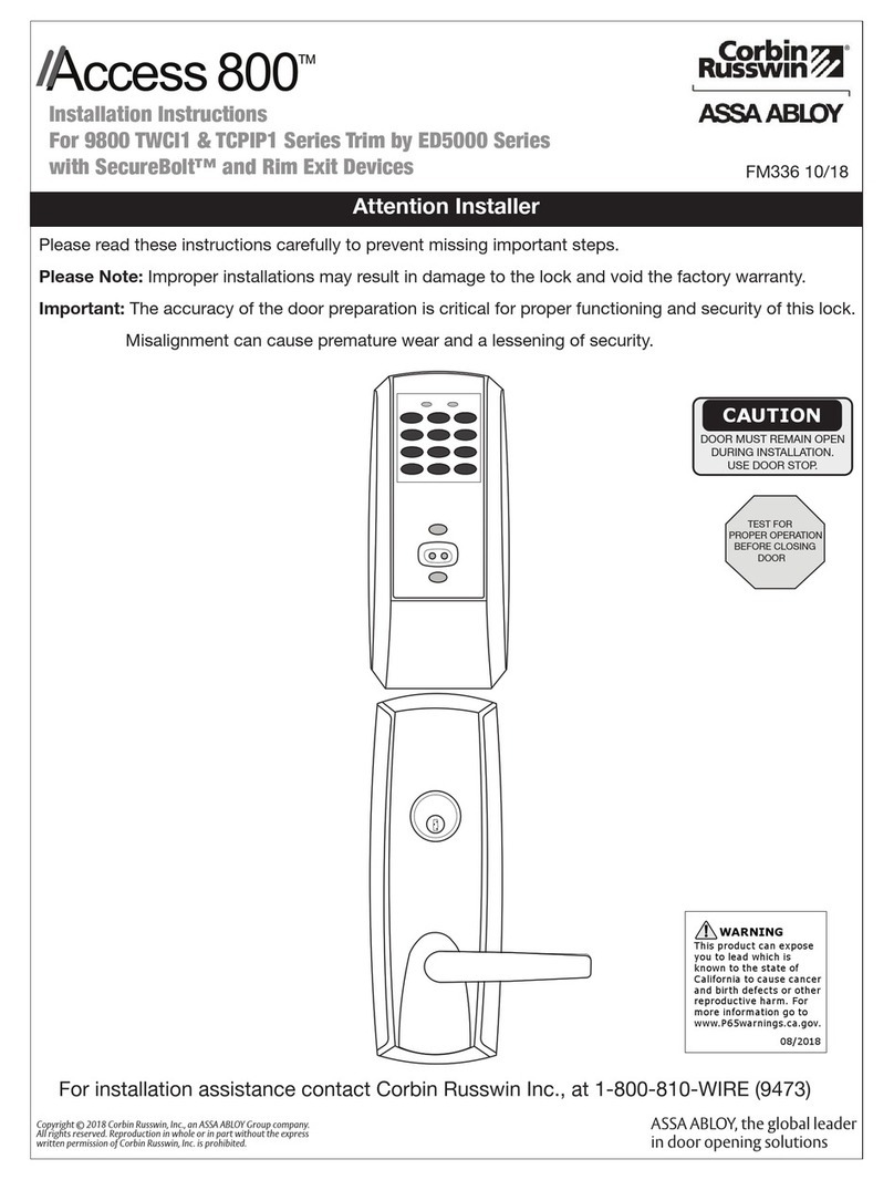
Assa Abloy Corbin Russwin Access 800 9800 TCWI1 Series User manual
Assa Abloy
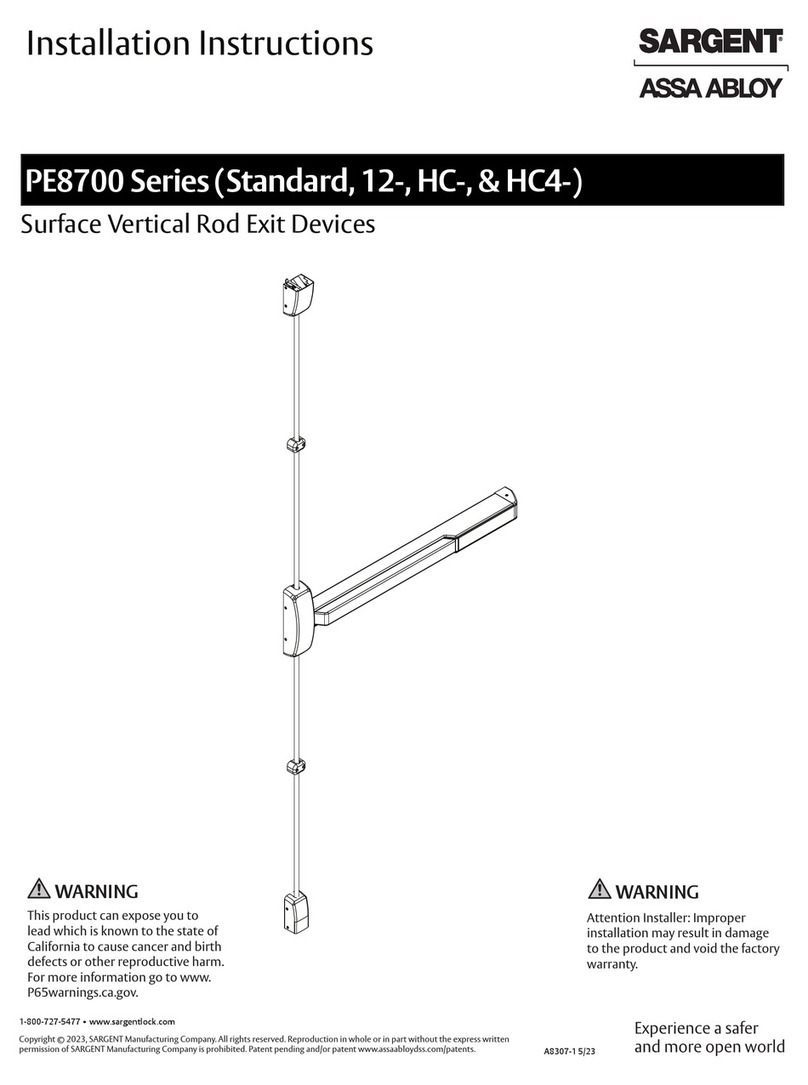
Assa Abloy Sargent PE8700 Series User manual
Assa Abloy
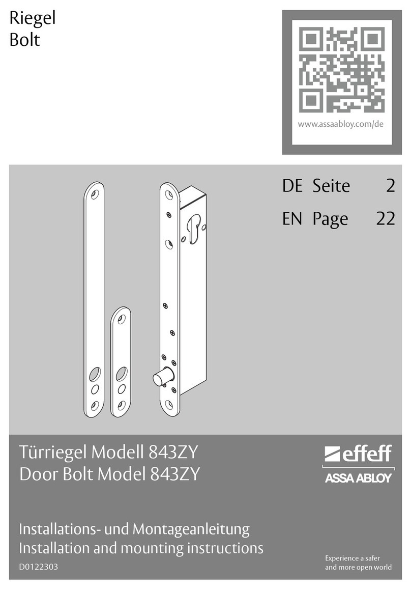
Assa Abloy effeff 843ZY-1 Q41 Series User manual
Assa Abloy
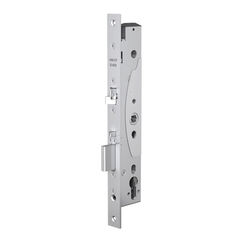
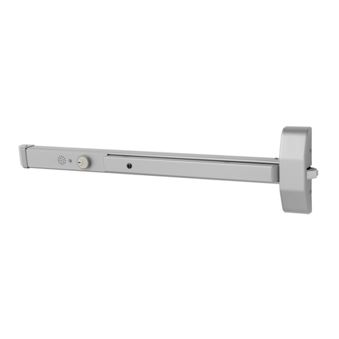
Assa Abloy PE920 User manual
Assa Abloy
Assa Abloy SARGENT 5300 Series User manual
Assa Abloy
Assa Abloy Corbin Russwin ED8400 Series User manual

Assa Abloy
Assa Abloy 332 E91 Series User manual
Assa Abloy
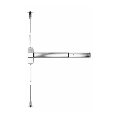
Assa Abloy Connect 50 User manual
Assa Abloy
Assa Abloy Corbin Russwin ED5800 Series User manual
Assa Abloy
Assa Abloy Sargent 7300 Series User manual
Assa Abloy
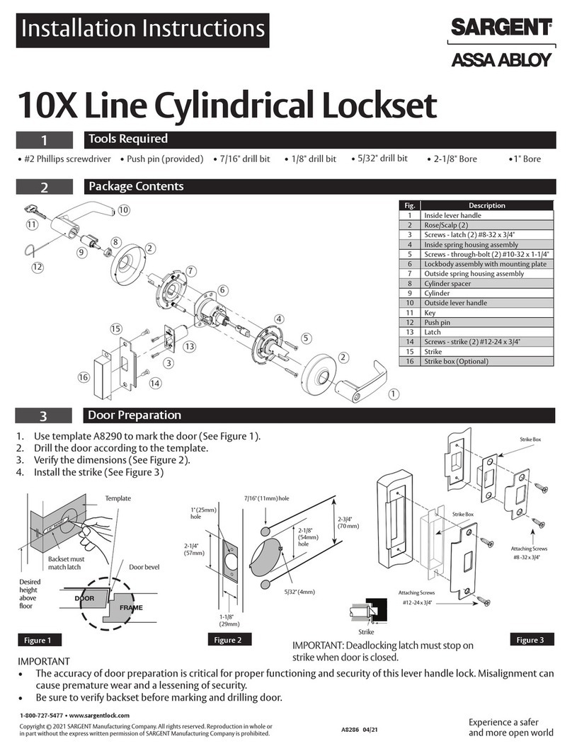
Assa Abloy SARGENT 10X Series User manual
Assa Abloy
Assa Abloy Corbin Russwin ED7800 Series User manual

Assa Abloy
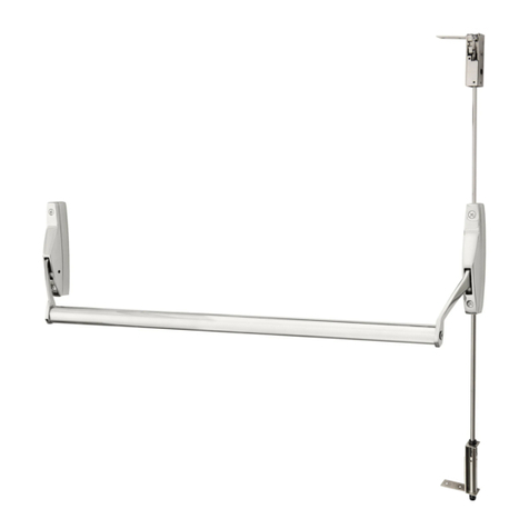
Assa Abloy Corbin Russwin MP6600 Series User manual
Assa Abloy
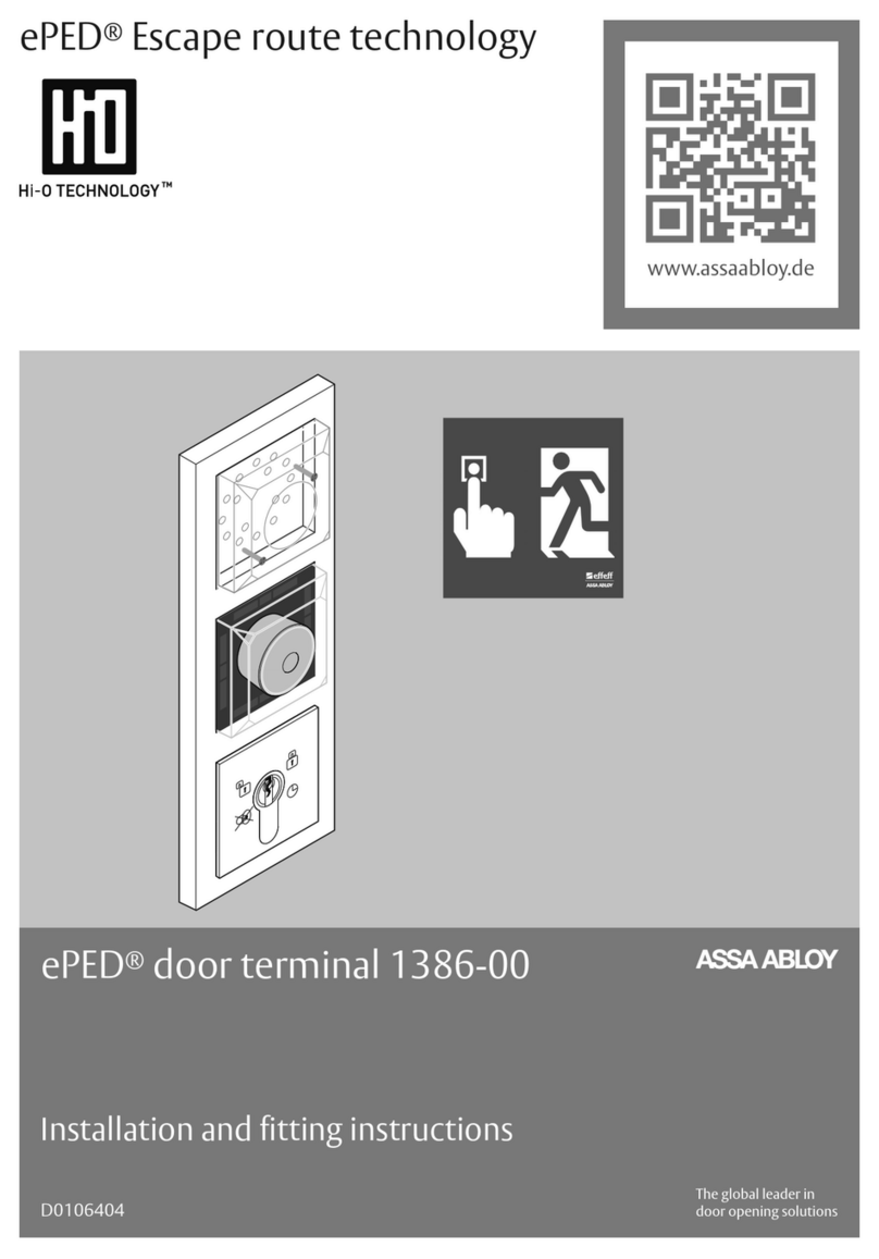
Assa Abloy ePED 1386-00 User manual

Assa Abloy
Assa Abloy h.e.s. 9200 Series Manual

Assa Abloy
Assa Abloy Arrow Revolution U4A-YRHCPZW0 Technical specifications

Assa Abloy
Assa Abloy Corbin Russwin Access 600 CL33600 TCRNE1... User manual
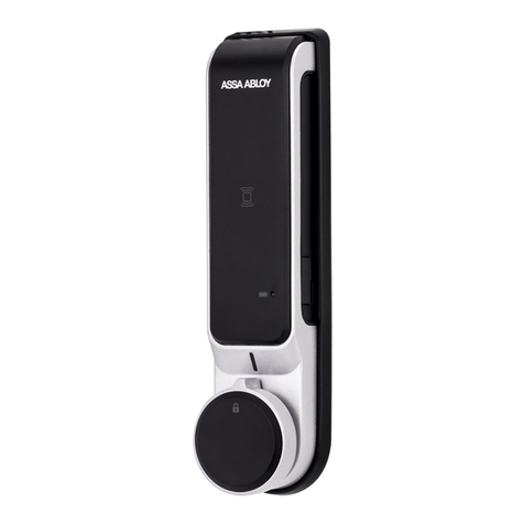
Assa Abloy
Assa Abloy ML52RA User manual
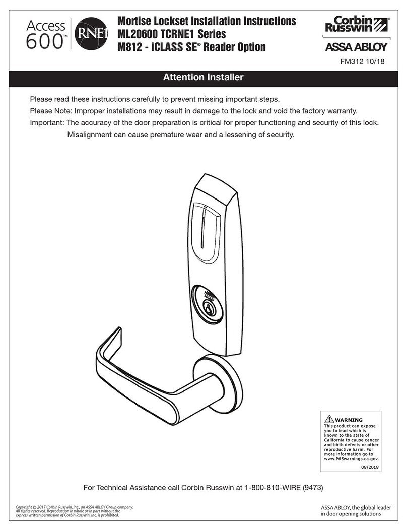
Assa Abloy
Assa Abloy Corbin Russwin Access 600 CL33600 TCRNE1... User manual
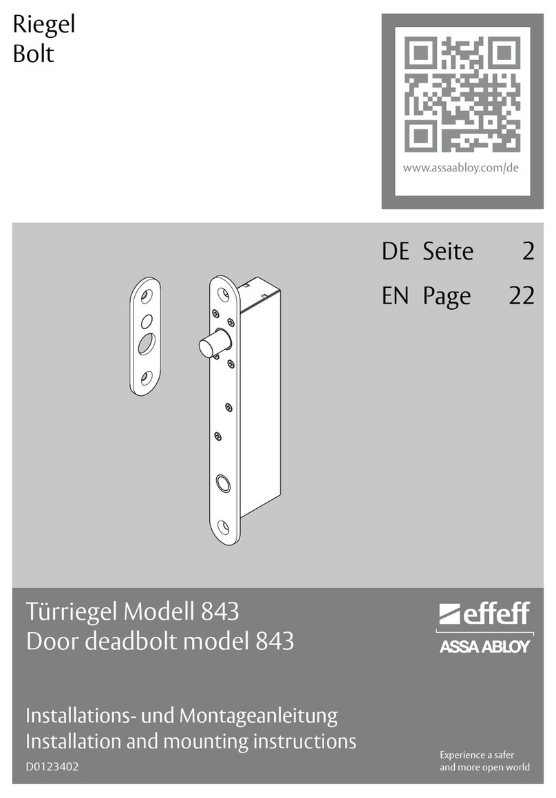
Assa Abloy
Assa Abloy effeff 843 User manual
Popular Door Lock manuals by other brands

SCOOP
SCOOP Pullbloc 4.1 FS Panik Assembly instruction

Yale
Yale MORTISE 8800 SERIES installation instructions

Siegenia
Siegenia KFV AS3500 Assembly instructions

Saflok
Saflok Quantum ädesē RFID installation instructions

ArrowVision
ArrowVision Shepherd 210 installation manual
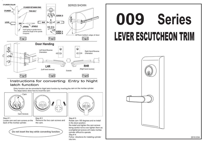
Baldwin
Baldwin 009 Series quick start guide
