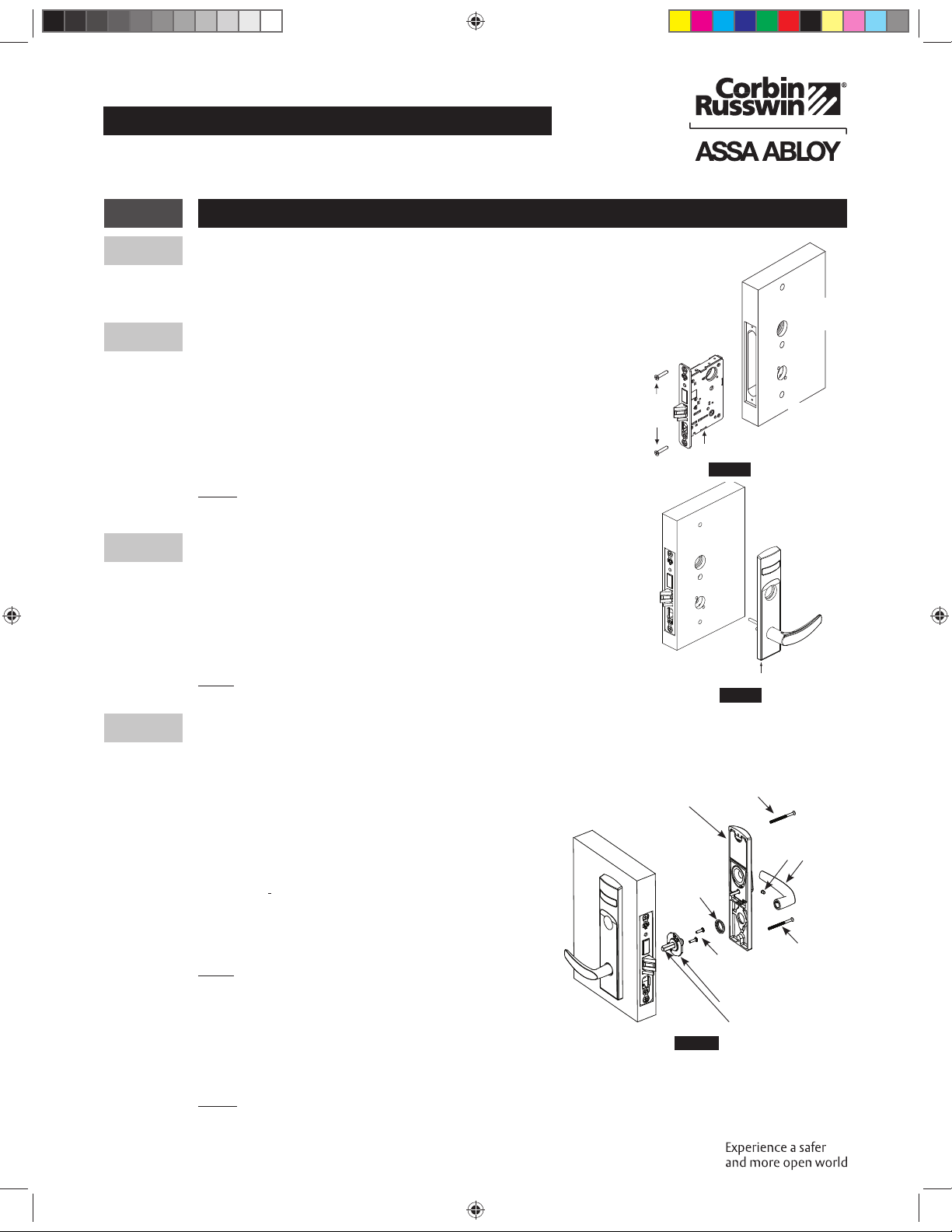
Assa Abloy Corbin Russwin MP6600 Series User manual
Other Assa Abloy Door Lock manuals

Assa Abloy
Assa Abloy Corbin Russwin ED2400 Series User manual

Assa Abloy
Assa Abloy OneSystem N1940 User manual

Assa Abloy
Assa Abloy Yale YDM3109A User manual

Assa Abloy
Assa Abloy Access 3 User manual

Assa Abloy
Assa Abloy Hes 5200 Series User manual

Assa Abloy
Assa Abloy effeff MAGG1200SM User manual

Assa Abloy
Assa Abloy 179E-2 User guide

Assa Abloy
Assa Abloy Yale YDME 50 NxT User manual

Assa Abloy
Assa Abloy IKON VERSO CLIQ User manual

Assa Abloy
Assa Abloy ENTR User manual

Assa Abloy
Assa Abloy Corbin Russwin FE6600 Series User manual

Assa Abloy
Assa Abloy 118 Series User manual

Assa Abloy
Assa Abloy SARGENT KP8977 Guide

Assa Abloy
Assa Abloy Yale 8800 Series User manual

Assa Abloy
Assa Abloy Sargent Passport 1000 PG User manual

Assa Abloy
Assa Abloy Yale Conexis L1 User manual

Assa Abloy
Assa Abloy Sargent PE8500 Series User manual

Assa Abloy
Assa Abloy EMTEK LISCIO Troubleshooting guide

Assa Abloy
Assa Abloy Sargent Profile G1 Series User manual

Assa Abloy
Assa Abloy Lockwood Cavity Lock User manual


Popular Door Lock manuals by other brands


SCOOP
SCOOP Pullbloc 4.1 FS Panik Assembly instruction

Yale
Yale MORTISE 8800 SERIES installation instructions

Siegenia
Siegenia KFV AS3500 Assembly instructions

Saflok
Saflok Quantum ädesē RFID installation instructions

ArrowVision
ArrowVision Shepherd 210 installation manual

Baldwin
Baldwin 009 Series quick start guide