manuals.online logo
Brands
  1. Home
  2. •
  3. Brands
  4. •
  5. Balanced Body
  6. •
  7. Fitness Equipment
  8. •
  9. Balanced Body Tower Bracket Retrofit Kit User manual

Balanced Body Tower Bracket Retrofit Kit User manual

Balanced Body is not responsible for any damage caused by
incorrect assembly.
BEFORE BEGINNING ASSEMBLY
These instructions include a parts list. Please use this list to make
sure you have all the parts necessary for installation. If you are
missing a part, please contact our customer service department
at 1-800-PILATES (1-800-745-2837).
Note: If you have ordered a Tower bracket kit for a Reformer with
casters, refer to Appendix II for additional instructions.
If you had your frame Pre-drilled by the factory remove ALL
hardware installed into the holes used for the tower bracket and
angle brackets. The hardware removed is no longer needed.
REQUIRED TOOLS (NOT INCLUDED)
»Hammer
»Power drill
»Socket wrench with 7/16” and 1/2” sockets
PARTS FOR TOWER (INCLUDED)
ITEM PART NO QTY
Vertical Tower frame tubes with
eyebolts installed TRP0105 2
Horizontal Tower tube with eyebolts
and corner connectors TRP0100 1
Push-Through Bar for Slider assembly 707-287 1
Yellow trap springs SPR9002 2
Blue trap springs SPR9004 2
Roll down bar 710-010 1
Yellow long springs SPR9006 2
Purple long springs SPR9461 2
Single cotton loops (pair) 101-005 1
Safety strap for tower with carabiner 210-058 1
Push Through Bar Slider assembly N/A 2
Push Through Bar Slider shoulder bolt 619-202 2
21mm x 1/2 inch wrench ALL0060 1
PARTS FOR THE TOWER BRACKET KIT
(INCLUDED)
ITEM PART NUMBER QTY
Tower Bracket 722-001 1
L shaped corner brackets 622-001 4
5/32" Allen wench GEN9282 1
3/16" Allen wrench GEN9280 1
21/64" drill bit TOL1059 1
1/4" drill bit GEN5555 1
Riser Receivers* REF0048 (left)
REF0049 (right) 2
Risers with pulleys installed* 950-184 2
Riser retention pins* GEN9402 2
Black plastic lanyards for riser pins* GEN9037 2
1/4"-20 x 2-1/4" Button Head Screws GEN7314 6
1/4"-20 x 3" Eyebolts GEN9232 4
1/4" Flat washers GEN9305 18
1/4"-20 Nylock nuts GEN9021 12
5/16"-18 x 1-3/4" Carriage bolts 210-512 4
Large (5/16"-18) Nylock nuts GEN9013 4
No. 10 finish washers 210-050 4
*Not included if ordered for Reformer with casters.
How to Assemble Your Tower Bracket Retrofit Kit
IMPO RTANT:
This is a relatively complex installation procedure. It involves drilling holes into the Reformer frame. Please read through these
instructions before proceeding. If you are uncomfortable undertaking any part of this procedure, it is highly recommended that
someone with a serviceable knowledge of equipment assembly and tools install the bracket.
Contact Us
1-800-PILATES | +1-916-388-2838
pilates.com | info@pilates.com
400-349 | 01.30.19
ASSEMBLY TIME
Approximately 90 minutes.
PREPARE YOUR WORKSPACE
Make sure you have enough physical space around the Reformer
to work, especially at the head-end of the machine where the
bracket kit will be attached. Remove the ropes from the risers
and the carriage. Attach carriage springs to the springbar to
secure the carriage at the foot-end of the Reformer. It is
recommended that you place a drop cloth or sheet under the
head-end of the Reformer, as there will be sawdust from drilling
holes in the frame.
REMOVE WOODEN RISER BLOCKS
1. Use the 5/32” Allen key to
remove bolts that attach
wooden risers from head-end
of Reformer (See Figure A).
2. Remove the risers and re-insert the bolts from the outside of
the frame so they are about half-way tightened.
3. Tap the heads of the bolts with a hammer until the propeller
nuts come out of the Reformer frame.
4. Unscrew the bolts from the propeller nuts and remove them
from the frame.
5. Put the risers, propeller nuts and bolts aside. They are no
longer needed.
INSTALL THE TOWER BRACKET ON THE REFORMER
6. Place Tower bracket on
outside of the Reformer
frame. Bracket flanges
should match up with holes
previously used to secure
the riser blocks to the frame
(See Figure B).
7. Make sure the bracket is centered.
8. Insert an eyebolt through a
No. 10 finish washer and a
1/4” washer into the indicated
bracket top and bottom holes
(See Figures C & D).
9. Align the riser on the inside
of the frame so that the two
flanges are on the top and
the single flange is on the
bottom. The flanges closer
to the outside of the frame
should line up with the
existing holes used for the wood risers (See Figures E & F).
10. Use a socket wrench to secure
both the top and bottom
eyebolt ends with a 1/4” flat
washer and a small, 1/4”-20
nylock nut (See Figure E).
11. Repeat steps 8-10 for the
other side of the bracket.
12. The Tower bracket should now be secured on the head-
end of the Reformer. This attached bracket will serve as a
template for drilling the remaining holes required to complete
assembly.
13. Use the provided 1/4” drill
bit (smaller drill bit) to drill a
hole from the inside of the
frame through the top inside
flange of the receiver bracket
and through the frame (See
Figure G).
14. From the outside of the
frame, insert the 2-1/4”
button head screw with a 1/4”
washer (See Figure H).
15. Slip the black plastic lanyard
loop over the protruding bolt
on the top inside flange and
then secure a small nylock
nut with a 7/16” socket as
shown in Figure I. The riser
pin is used to secure the new
risers into the receivers.
The loop is secured on a bolt.
16. Repeat steps 13-15 on the other riser.
17. Position the 21/64” drill bit
through the hole in the front
of the riser, through the
receiver itself, until you make
contact with the wood of the
frame. (See Figure J).
18. Holding the drill steady and
level, drill into the Reformer
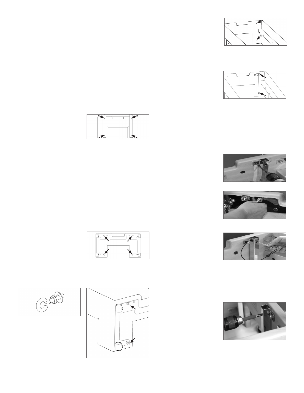
Figure A: Remove the bolts from risers.
Figure B: Match bracket with the 4
holes left by the risers.
Figure E: Match outside flanges with
protruding bolt ends.
Figure C: Eyebolt with No. 10 finish
washer and 1/4” washer.
Figure G: Drill through inside flanges
Figure H: Install the bolt and washer
from outside of frame.
Figure I: Lanyard is secured to the bolt
with a small nylock nut.
Figure J: Drill through receiver and
into Reformer until drill bit hits the
mounting plate.
Figure D: Insert eyebolt through
existing holes.
Figure F: Align outer flanges on
receiver with existing holes in
Reformer frame, and secure with a flat
washer and nylock nut.
2
frame until the be drill bit hits the inside face of the mounting
bracket on the outside face.
19. Repeat the process on the other receiver.
20.Insert the metal risers into the receivers and secure them at
the desired height with the riser pin.
INSTALL CORNER BRACKETS
Locate the four L-shaped brackets that go on the top and bottom
of each inner corner at the head-end of the Reformer frame.
These corner brackets provide additional support for the Tower
bracket.
21. Use the provided 21/64” drill bit (larger drill bit). Slowly drill (4)
four holes through the frame from the outside using the
bracket to guide the holes (See Figure K).
22.From the outside of the head-
end of the frame, insert a
2-1/4” button head screw and
a 1/4” washer into the holes
drilled (See Figure K).
23.Place corner brackets with
the short flange on the inside
head-end of the frame and
the longer flange flush on
the inner, long side of the
Reformer (See Figure L).
24.Secure the corner bracket with 1/4” washer and a small nylock
nut. Make sure bracket fits tightly against the side rail and is
level.
25.Using the 21/64” drill bit, from the inside of the frame drill
through the hole in the long side of the corner bracket and
drill into the frame. Drill slowly with light pressure.
Note: Be particularly careful drilling-- it is easy to splinter the
outside of the frame. Hold the drill steady and level - it is a
good idea to use two hands during this step.
26.From the outer side of frame,
insert carriage bolt into drilled
hole (See Figure M).
27. Secure on inner side with
5/16” large nylock nut.
28.Repeat steps 26-28 on the other corner brackets.
INSERT VERTICAL TOWER TUBES
29. Loosen setscrews on circular tube receivers on the Tower
bracket using the 3/16” Allen wrench (See Figure N).
30.Remove the vertical tower
system and place them into
the receiver bracket on the
end of the Reformer. The
knobs of the sliders will be
facing outwards as shown in
Figure O. Make sure when you place the tubes into the
receiver that the loop is facing forward, towards the carriage,
see Figure P.
HOW TO ADJUST YOUR SLIDING PUSH THROUGH BAR
Position your hands on the outside of each slider. Place your
middle and/or ring fingers under the silver base of the knob; right
where the black body of the knob threads into. Place your index
finger and thumb around the knob itself. Pull each of the knobs
outwards, away from the vertical tubes, until they stop. Using the
same force on each arm, move the slider upwards or downwards
to each new location. Once you near a new location slightly
release the outward pull of the knobs. The pins will automatically
fall into the next position when aligned.
WEEKLY MAINTENANCE
Inspect springs for separations, and replace if needed. Inspect
snaps on springs and make sure the retractors operate smoothly.
Replace them if worn or do not operate freely. Make sure that
there are no indentations on the inside of the hooks.
Inspect all nuts, eyebolts and setscrews for tightness. Tighten or
replace if necessary.
It is recommended to check to ensure the pins in the plunger
knobs protrude and lock into the vertical tubes. First pull both
knobs out and start moving the sliders to a different position.
Release the knobs before the next hole and continue to slide the
system. Once over a hole the pin of the knob will drop into the
opening. Once each slider is in a new position apply a down force
on the PTB directly downwards. The pins of the sliders should
Figure K: Drill holes through areas
indicated.
Figure L: Corner bracket mounting
location.
Long Side
Short Side
Figure M: Carriage bolt locations.
Figure N: Insert Tower tubes into tube
receivers.
Figure O
Knobs
outward
Figure P
Loop should face
the reformer.
3
not come out of the holes. If the pins do not stay in the tube
holes, the pull knobs need to be replaced; call Balanced Body for
replacement parts
OPTION: INSTALLING THE TWIN MATS
1. Pull pins and lower risers.
2. Detach all springs from springbar and move the carriage
toward the head end of the frame.
3. Rotate the footbar support up to the padded section of the
footbar and then lay the footbar down onto the frame rails. It
should now be inside the frame and lower than the top of the
frame.
4. Remove shoulder rests from the carriage. If the shoulder rests
are not detachable, the carriage will need to be turned upside
down
(See Appendix I).
5. Vinyl flaps are installed inside the mat for shipping purposes.
Detach, rotate and reinstall flaps so that they hang down from
the edge of the mat aligned with the eyebolts.
6. Place the mat with the vinyl flaps at the head-end of the
Reformer with flaps facing the Tower. The vinyl flaps should
hang over the head-end of the frame. They are designed
to protect the Reformer frame when using the PTB with a
bottom spring.
7. Place the remaining mat on the foot-end of the Reformer.
Make sure the end of the mat with the feet further from the
edge is installed over the standing platform.
APPENDIX I: TURNING THE CARRIAGE UPSIDE DOWN
Note: Use only if the shoulder rests are not detachable. To protect
the upholstery, make sure the Reformer rails are clean before
beginning.
1. Detach the springs from the springbar.
2. Carriage should be positioned at the riser end of the frame.
3. Rest the loops and ropes on the floor under the Reformer.
4. Lifting the head end of the carriage, turn it upside down so
the upholstery is resting on the metal rails.
APPENDIX II: INSTALLING THE TOWER BRACKET ON A
REFORMER WITH CASTERS
ADDITIONAL PARTS FOR THE TOWER BRACKET KIT
FOR REFORMERS WITH CASTERS (INCLUDED)
ITEM PART NUMBER QTY
Flathead allen bolt 210-216 2
1/4” Washer GEN9305 2
1/4”-20 Nylock nut GEN9021 2
If you have a Reformer with casters instead of risers, you will not
receive metal risers with your Tower Bracket Kit. Use these steps
instead of regular step #1-21.
1. Remove the top two bolts from each caster and set them
aside.
2. Insert one flathead Allen bolt
into the existing top outer
hole and secure on the inside
of the reformer frame with a
washer and a nut (See Figure
Q). Make sure the head of the
bolt is flush with the surface
of the frame. Repeat on the other side.
3. Mount the Tower bracket to
the outside of the frame.
Align the two inner holes
from the caster bolts (with
no flatheads) with two of
the holes along the top of
the bracket. Make sure the
bracket is centered (See Figure R).
4. Insert an eyebolt with a No. 10 finish washer and a 1/4” washer
through the centermost holes from the outside of the frame.
5. Use the mounted Tower
bracket as a guide to drill the
remaining six holes on the
head end of the frame (See
Figure S). Use the acorn nuts
to secure the fasteners from
the inside of the frame with a 7/16” wrench.
6. Continue mounting the bracket as in steps 22-36.
Figure Q: Insert flathead allen bolts
here.
Figure R: Center Tower bracket on
inner caster holes.
Figure S: Drill the remaining holes.
Contact Us
1-800-PILATES | +1-916-388-2838
pilates.com | info@pilates.com
400-349 | 01.30.19

Other Balanced Body Fitness Equipment manuals

Balanced Body Cadillac Trapeze Table Administrator Guide

Balanced Body

Balanced Body Cadillac Trapeze Table Administrator Guide

Balanced Body Rialto with Riser Konnector Instruction Manual

Balanced Body

Balanced Body Rialto with Riser Konnector Instruction Manual

Balanced Body Allegro 1B Instruction Manual

Balanced Body

Balanced Body Allegro 1B Instruction Manual

Balanced Body Konnector Instruction Manual

Balanced Body

Balanced Body Konnector Instruction Manual

Balanced Body Allegro Reformer Administrator Guide

Balanced Body

Balanced Body Allegro Reformer Administrator Guide

Balanced Body CoreAlign User manual

Balanced Body

Balanced Body CoreAlign User manual

Balanced Body CenterLine Tower Retrofit Instruction Manual

Balanced Body

Balanced Body CenterLine Tower Retrofit Instruction Manual

Balanced Body Pilates IQ Reformer Manual

Balanced Body

Balanced Body Pilates IQ Reformer Manual

Balanced Body Allegro 1A Instruction Manual

Balanced Body

Balanced Body Allegro 1A Instruction Manual

Balanced Body Tower on the Allegro 2 Instruction Manual

Balanced Body

Balanced Body Tower on the Allegro 2 Instruction Manual

Balanced Body CoreAlign Quick setup guide

Balanced Body

Balanced Body CoreAlign Quick setup guide

Balanced Body Konnector LITE Instruction Manual

Balanced Body

Balanced Body Konnector LITE Instruction Manual

Balanced Body Reformer Trapeze Combination User manual

Balanced Body

Balanced Body Reformer Trapeze Combination User manual

Balanced Body Rialto Reformer User manual

Balanced Body

Balanced Body Rialto Reformer User manual

Balanced Body Exo Chair Guide

Balanced Body

Balanced Body Exo Chair Guide

Balanced Body Allegro 2 Reformer Programming manual

Balanced Body

Balanced Body Allegro 2 Reformer Programming manual

Balanced Body Avalon Chair User manual

Balanced Body

Balanced Body Avalon Chair User manual

Balanced Body CenterLine Reformer User manual

Balanced Body

Balanced Body CenterLine Reformer User manual

Balanced Body Pilates Arc User manual

Balanced Body

Balanced Body Pilates Arc User manual

Balanced Body Allegro Instruction sheet

Balanced Body

Balanced Body Allegro Instruction sheet

Balanced Body Allegro Administrator Guide

Balanced Body

Balanced Body Allegro Administrator Guide

Balanced Body Duet User manual

Balanced Body

Balanced Body Duet User manual

Balanced Body Wall Tower Administrator Guide

Balanced Body

Balanced Body Wall Tower Administrator Guide

Balanced Body Allegro CC User manual

Balanced Body

Balanced Body Allegro CC User manual

Popular Fitness Equipment manuals by other brands

Energetics 5300416 manual

Energetics

Energetics 5300416 manual

HMS LS3050 Manual instruction

HMS

HMS LS3050 Manual instruction

dynarex 10502 quick start guide

dynarex

dynarex 10502 quick start guide

Crivit 285684 Operation and safety notes

Crivit

Crivit 285684 Operation and safety notes

Inova maxi climber user manual

Inova

Inova maxi climber user manual

Eleiko SVR INSERT PLATFORM PRESTERA DOUBLE HALF manual

Eleiko

Eleiko SVR INSERT PLATFORM PRESTERA DOUBLE HALF manual

Align-Pilates Wall Unit & Barre Bar installation instructions

Align-Pilates

Align-Pilates Wall Unit & Barre Bar installation instructions

ParaBody 801101 Assembly instruction sheet

ParaBody

ParaBody 801101 Assembly instruction sheet

TaiShan TQ2550/A Installation

TaiShan

TaiShan TQ2550/A Installation

Dittmann HFE 322 Usage instructions

Dittmann

Dittmann HFE 322 Usage instructions

Thinkrider A1 user manual

Thinkrider

Thinkrider A1 user manual

Weider 2100 user manual

Weider

Weider 2100 user manual

Tunturi WB50 user manual

Tunturi

Tunturi WB50 user manual

Gibbon SlackRack 300 user guide

Gibbon

Gibbon SlackRack 300 user guide

MARBO-SPORT MP-U225 Assembly instruction

MARBO-SPORT

MARBO-SPORT MP-U225 Assembly instruction

SteelFlex CTH-1100.1 owner's manual

SteelFlex

SteelFlex CTH-1100.1 owner's manual

Weider WESY1938.1 user manual

Weider

Weider WESY1938.1 user manual

Spartan KH-385 manual

Spartan

Spartan KH-385 manual

manuals.online logo
manuals.online logoBrands
  • About & Mission
  • Contact us
  • Privacy Policy
  • Terms and Conditions

Copyright 2025 Manuals.Online. All Rights Reserved.